Language selection

Search

Patent 1294535 Summary

Third-party information liability

Some of the information on this Web page has been provided by external sources. The Government of Canada is not responsible for the accuracy, reliability or currency of the information supplied by external sources. Users wishing to rely upon this information should consult directly with the source of the information. Content provided by external sources is not subject to official languages, privacy and accessibility requirements.

Claims and Abstract availability

Any discrepancies in the text and image of the Claims and Abstract are due to differing posting times. Text of the Claims and Abstract are posted:

  • At the time the application is open to public inspection;
  • At the time of issue of the patent (grant).
(12) Patent: (11) CA 1294535
(21) Application Number: 1294535
(54) English Title: BLIND IN WINDOW SUPPORT
(54) French Title: SUPPORT DE STORE VENITIEN DANS UN VITRAGE MULTI-EPAISSEUR
Status: Expired and beyond the Period of Reversal
Bibliographic Data
(51) International Patent Classification (IPC):
  • E06B 9/264 (2006.01)
(72) Inventors :
  • BAIER, BRUCE A. (United States of America)
(73) Owners :
  • PELLA CORPORATION
(71) Applicants :
  • PELLA CORPORATION (United States of America)
(74) Agent:
(74) Associate agent:
(45) Issued: 1992-01-21
(22) Filed Date: 1988-03-28
Availability of licence: N/A
Dedicated to the Public: N/A
(25) Language of filing: English

Patent Cooperation Treaty (PCT): No

(30) Application Priority Data:
Application No. Country/Territory Date
136,010 (United States of America) 1987-12-21

Abstracts

English Abstract


ABSTRACT OF THE DISCLOSURE
A venetian blind support for a between-the-pane window
blind includes an anchor clip secured to the bottom of the
upper window frame rail detachably engaged by an anchor bar
connected to the window blind by a rod-type hook. The
support is self-centered in the window frame and the blind
is self-centered as it is held by the support.


Claims

Note: Claims are shown in the official language in which they were submitted.

The embodiments of the invention in which an exclusive
property or privilege is claimed are defined as follows:
1.
A blind in window support, comprising:
a blind support having a horizontally disposed leg including an
upstanding ledge and a vertical opening extending through
said ledge, and
a blind hook having an L-shaped rod portion on its upper end
extending through said opening with a horizontal leg being
pivotally supported on said ledge.
2.
The structure of claim 1 wherein said ledge on one side
merges into a valley.
3.
The structure of claim 2 wherein said horizontal leg of
said blind hook extends beyond said ledge and over said valley
whereby pivoting of said blind hook is freely permitted in the
vertical plane of said blind hook L-shaped portion with the
free end of said horizontal leg at times extending downwardly
toward said valley while a shoulder at the juncture of said
ledge with said valley becomes a pivot point for said blind
hook.
4.
The structure of claim 3 wherein an eye is provided on the
lower end of said blind hook adapted to pivotally engage the
axial rod of the top blind slat.
5.
The structure of claim 1 wherein said blind support
includes an upstanding shoulder along one side adapted to
engage a vertical side of a top window rail to function as a
-7-

stop to locate said blind in said window relative to the window
pane.
6.
A blind in window support comprising:
a blind support having an anchor clip adapted to be secured to
a window top rail,
an anchor bar adapted to be secured to the top end of a blind,
said anchor clip having a downwardly extending hook means and
said anchor bar having an upwardly extending hook means
detachably engaging said downwardly engaging hook means,
said downwardly and upwardly extending hook means each
including L-shaped portions having substantially
horizontally extending legs in registry,
the L-shaped portion of said upwardly extending hook means on
said anchor bar being one of two L-shaped portions with
the second L-shaped portion extending downwardly and
having a horizontal leg adapted to be secured to a blind,
and the vertical legs of the first and second L-shaped
portions being interconnected,
said horizontal leg on said second L-shaped portion including a
hole adapted to receive a rod-shaped blind hook, said
horizontal leg of said second L-shaped portion being
further defined as including a ledge, and said hole
extending through said ledge, said ledge terminating in a
valley on one side, and
said blind hook including an L-shaped portion on its upper end
which extending through said hole and the horizontal leg
of said rod-shaped L-shaped portion being supported on
said ledge.
- 8 -

7.
The structure of claim 6 wherein said horizontal leg of
said blind hook extends beyond said ledge and over said valley
whereby pivoting of said blind hook is freely permitted in the
vertical plane of said blind hook L-shaped portion with the
free end of said horizontal leg at times extending downwardly
towards said valley while a shoulder at the juncture of said
ledge with said valley becomes a pivot point for said blind
hook.
8.
The structure of claim 7 wherein an eye is provided on the
lower end of said blind hook adapted to pivotally engage the
axial rod of the top blind slot.
9.
A blind support, comprising:
a blind,
a blind support having an anchor clip adapted to be secured to
a window top rail,
an anchor bar adapted to be secured to the top end of a blind,
said anchor clip having a downwardly extending hook means and
said anchor bar having an upwardly extending hook means
detachably engaging said downwardly engaging hook means,
said downwardly and upwardly extending hook means each
including L-shaped portions having substantially
horizontally extending legs in registry, and
said horizontally extending legs in registry are further
defined by said leg of said anchor clip sloping upwardly
and said leg of said anchor bar sloping downwardly said
anchor clip and anchor bar legs each having cooperating
- 9 -

interlocking shoulders, whereby the hooking action between
said anchor clip and said anchor bar increases as the
weight on said anchor bar increases.
10.
A blind support, comprising:
a blind,
a blind support having an anchor clip adapted to be secured to
a window top rail,
an anchor bar adapted to be secured to the top end of a blind,
said anchor clip having a downwardly extending hook means and
said anchor bar having an upwardly ending hook means
detachably engaging said downwardly engaging hook means,
said downwardly and upwardly extending hook means each
including L-shaped portions having substantially
horizontally extending legs in registry, and
said horizontally extending legs in registry are further
defined by said leg of said anchor clip being cantilevered
and extending in one direction and the leg of said anchor
bar being cantilevered and extending in the opposite
direction and being disposed on top of said leg of said
anchor clip, said anchor clip and anchor bar legs each
having cooperating interlocking shoulders, whereby said
anchor bar is totally supportably engaged and disengaged
from said anchor clip by moving said anchor bar upwardly
and laterally horizontally towards and away from said
anchor clip respectively.
- 10 -

Description

Note: Descriptions are shown in the official language in which they were submitted.


~;~94S35
BACKGROUND OF THE INVENTION
A blind in the window between the panes has been a very
popular window product made popular by Rolscreen Company,
Pella, Iowa, as disclosed in one of their representative U.S.
patent 3,389,737 dated June 25, 1968 by B.C. Arnold et al. and
sold under the trademark Slimshade ~. The blind of this window
is supported by a pair of hooks engaging the top slat of the
blind, and being secured to the top rail of the window frame by
screws. On the ~ob site installation of the blind in the
window is required on the part of the installer, and careful
selection of the spot where the screws are inserted into the
top window rail is necessary; otherwise the blind will not be
centered either from side to side or front to back in the
window frame and interference will result when the slats are
adjusted.
It would be desirable to have a self-centering support for
a between the pan~ blind which is easily assembled and
disassembled by the installer or the user and which would
operate smoothly and freely at all times.
SUMMARY OF THE INVENTION
The window blind support of this invention includes an
anchor clip which is pre-sized to the window frame to be
secured under the top rail of the window. An anchor bar
supports the blind through rod-type hooks and engages the
anchor clip in a hook-like fashion, and thus may be quickly
installed in place or removed. The anchor clip has a downward
extending L-shaped member which registers with an upwardly
extending L-shaped member on the anchor bar, with the
horizontal legs of the L-shaped members extending in
3~
--2--

12~4S35
opposite directions whereby the weight of the blind locks
the anchor bar to the anchor clip. Shoulders on the horizontal
legs of tl~e anchor bar and anchor clip are in engagement and
further limit inadvertent disassembly. An upstanding
shoulder on the anchor clip engages the front face of the
upper window rail and thereby locates the blind at the
proper distance between the panes.
A rod-type hook includes an eye on its lower end which
engages the upper slat of the blind and has an L-shaped
upper end which extends through a hole in the horizontal leg
o a second L-shaped portion of the anchor bar. The hori-
zontal leg of the second L-shaped portion includes a ledge
and a valley, with the L-shaped end of the rod-shaped hook
being normally supported on the ledge, but free to pivot in
all directions including from side to side where at times
the free end of the L-shaped hook end extends over and into
the valley as the blind hook pivots on the shoulder at the
juncture of the ledge and the valley.
The eye on the rod-shaped hook is shaped around the
axial rod of the top slat as the last step in assembling the
blind to the anchor bar and the horizontal leg of the first
L-shaped portion additionally functions to prevent accidental
disengagement of the blind hook from the anchor clip. This
is to say that at the factory, the rod-shaped blind hook is
inserted into the anchor har before it is connected to the
axial ro~, at which time the blind hook cannot be inadvertently
disengaged from the anchor bar.
~RIEF DESCRIPTION OF THE DRAWINGS
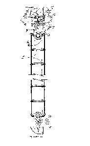
Figure l is a front plan view of a between-the-pane
--3--

lZ~1~535
blind supported by the support of this invention.
Figure 2 is a fragmentary enlarged perspective view
thereof.
Figure 3 is a ~ragmentary perspective view of the anchor
clip interlocked with the anchor bar and the blind hook
connected to the anchor bar.
Figure 4 is a cross-sectional view taken along line 4-4
in Figure 2.
Figure 5 is a cross-sectional view taken along line 5-5
in Figure 4.
DETAILED DESCRIPTION OF THE PREFERRED Et~BODIMENT
The blind support assembly of this invention is referred
to generally by the reference numeral 10 and is shown
supporting a venetian blind 12 in a window frame 14 having
top and bottom rails 16 and 18 and side stiles 20 and 22. A
control 24 is provided for through the pane adjustment of
the blind slats 26.
The support assembly 10 includes an anchor clip 30
detachably interlocked with an anchor bar 32 which supports
a rod-shaped blind hook 34 connected to the top slat 26 of
the blind 12.
The anchor clip 30 has an L-shaped portion 40 which
includes a horizontal le~ 42 and a vertical leg 44. The
anchor clip 30 includes a second L-shaped portion 46 having
a horizontal leg 48 and a vertical leg common to the verti-
cal leg 44 of the first L-shaped portion 40. The horizontal
leg 48 includes an upstanding shoulder 50 which engages the
front face 52 of the top window frame rail 16 as seen in
--4--

1294535
Figure 4 for purposes of locating and centering the hlind 12
between the window panes (not shown). A screw 55 secures
the anchor clip 30 to the window frame top rail 16. The
anchor clip 30 and the anchor bar 32 are the same width as
the window between the side stiles 20 and 22, and thus the
blind 12 will be centered from side to side without inter-
ference from the side stiles. The horizontal leg 42 of the
first L-shaped portion 40 extends towards the front side of
the window and includes a shoulder 54 which interlocks with
a shoulder 56 on a horizontal leg 5B of a first L-shaped
portion 60. L-shaped portion 60 includes a vertical leg 62
which is common to the second L-shaped portion 64 having a
horizontal leg 66.
The second horizontal leg 66 includes a ledge 68 which
merges into a valley 70 adjacent the vertical leg 62. The
rod-shaped blind hook 34 has an L-shaped end 72 which rests
on the ledge 68 and extends over the valley 70 such that the
hook 34 may pivot freely in the hole 80 to allow the blind
12 to self-center after temporary disalignment has occurred,
SUCIl as during storage or assembly and disassembly of the
blind in the window. The juncture at the ledge 68 and the
valley 70 forms a shoulder 82 which functions as the pivot
point for the hook 34 at times as it moves from side to side
as seen in Figure 4 by the dash line representations of the
hook.
The hook 34 also includes an eye 84 which is connected
to the axial rod 86 of the top slat 26, thus allowing the
blind 12 to float freely.
It is thus seen in assembly of the blind to the anchor
--5--

4535
clip 30 that the rod-shaped hook 34 is first threaded
through the hole 80 and then the eye 84 is formed around the
axial rod 86, ~hereby the blind is now locked onto the
anchor clip 30 but is allowed to freely float therefrom when
installed in the window frame 14. The horizontal leg 58 of
the anchor clip 30 limits the upward travel of the blind
clip 34.
On the job site, the anchor clip 30 is placed in the
window frame 14 under the top rail 16 with the upstanding
shoulder 50 engaging the front face 52 of the rail 16. The
screws 54 hold the clip 30 in place. Access to the screw
head is possible through an opening 90 in the horizontal leg
42 as seen in Figure 5. The lower end of the blind 12 is
secured to the bottom window rail 18 by an S-shaped hook 100
engaging a screw 102 having an eye. The upper end of the S-
shaped hook 100 engages the axial rod 104 of the bottom slat
26.

Representative Drawing
A single figure which represents the drawing illustrating the invention.
Administrative Status

2024-08-01:As part of the Next Generation Patents (NGP) transition, the Canadian Patents Database (CPD) now contains a more detailed Event History, which replicates the Event Log of our new back-office solution.

Please note that "Inactive:" events refers to events no longer in use in our new back-office solution.

For a clearer understanding of the status of the application/patent presented on this page, the site Disclaimer , as well as the definitions for Patent , Event History , Maintenance Fee  and Payment History  should be consulted.

Event History

Description Date
Time Limit for Reversal Expired 1998-01-21
Letter Sent 1997-01-21
Grant by Issuance 1992-01-21

Abandonment History

There is no abandonment history.

Owners on Record

Note: Records showing the ownership history in alphabetical order.

Current Owners on Record
PELLA CORPORATION
Past Owners on Record
BRUCE A. BAIER
Past Owners that do not appear in the "Owners on Record" listing will appear in other documentation within the application.
Documents

To view selected files, please enter reCAPTCHA code :


To view images, click a link in the Document Description column. To download the documents, select one or more checkboxes in the first column and then click the "Download Selected in PDF format (Zip Archive)" or the "Download Selected as Single PDF" button.

List of published and non-published patent-specific documents on the CPD .

If you have any difficulty accessing content, you can call the Client Service Centre at 1-866-997-1936 or send them an e-mail at CIPO Client Service Centre.


Document
Description 
Date
(yyyy-mm-dd) 
Number of pages   Size of Image (KB) 
Claims 1993-10-26 4 119
Drawings 1993-10-26 2 73
Abstract 1993-10-26 1 8
Cover Page 1993-10-26 1 9
Descriptions 1993-10-26 5 146
Representative drawing 2002-01-24 1 8
Fees 1995-12-19 1 66
Fees 1994-12-30 1 48
Fees 1993-12-20 1 63