Language selection

Search

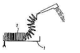
Patent 1295094 Summary

Third-party information liability

Some of the information on this Web page has been provided by external sources. The Government of Canada is not responsible for the accuracy, reliability or currency of the information supplied by external sources. Users wishing to rely upon this information should consult directly with the source of the information. Content provided by external sources is not subject to official languages, privacy and accessibility requirements.

Claims and Abstract availability

Any discrepancies in the text and image of the Claims and Abstract are due to differing posting times. Text of the Claims and Abstract are posted:

  • At the time the application is open to public inspection;
  • At the time of issue of the patent (grant).
(12) Patent: (11) CA 1295094
(21) Application Number: 1295094
(54) English Title: MOVABLE SHOWER ASSEMBLY HAVING AN AUTOMATICALLY RETRACTING HOSE AND A SHOWER HEAD CAPABLE OF TAKING UP MULTIPLE POSITIONS
(54) French Title: ENSEMBLE DE DOUCHE MOBILE COMPORTANT UN TUYAU A ESCAMOTAGE AUTOMATIQUE ET UNE POMME DE DOUCHE A POSITIONS MULTIPLES
Status: Expired and beyond the Period of Reversal
Bibliographic Data
(51) International Patent Classification (IPC):
  • E03C 1/06 (2006.01)
(72) Inventors :
  • COLL, ALAIN (France)
(73) Owners :
  • ALAIN COLL
(71) Applicants :
(74) Agent: SWABEY OGILVY RENAULT
(74) Associate agent:
(45) Issued: 1992-02-04
(22) Filed Date: 1987-05-27
Availability of licence: N/A
Dedicated to the Public: N/A
(25) Language of filing: English

Patent Cooperation Treaty (PCT): No

(30) Application Priority Data:
Application No. Country/Territory Date
86 08223 (France) 1986-06-06

Abstracts

English Abstract


A B S T R A C T
A movable shower assembly having an automatically retracting
hose and a shower head capable of taking up multiple positions
The invention relates to a assembly providing:
1) at rest, an automatically retracting hose which is
compact and which therefore does not hang over associated
sanitary ware;
2) in use, a greater length of hose than is possible with
conventional designs; and
3) a shower head which can be put into any convenient
position both when at rest and when in use, thus optimizing
shower comfort, this being achieved by a suction cup fixing
system (4).
The shower assembly is constituted by a support (1), a
hose (2), and a shower head (3), said hose is of round or
shaped cross section and is wound helically to constitute a
helical spring shape, and said shower head and said support
together constitute a housing for enclosing said hose when
retracted.


Claims

Note: Claims are shown in the official language in which they were submitted.

The embodiments of the invention in which
an exclusive property or privilege is claimed are
defined as follows:
1. A shower assembly, comprising: a support
(1) having a semi-cylindrical housing, a hose (2),
and a hand manipulable shower head (3) having at
least one concave surface in the form of a sector of
a cylinder, wherein said hose is of round or shaped
cross section and is wound helically to constitute a
helical spring shape, wherein said shower head and
said support together constitute a housing for at
least partially enclosing said hose when retracted
and wherein the shower head comprises an elongate
hand grip portion followed by a water outlet nozzle,
an outlet end of the hose being coupled to the shower
head proximate an interface region between the hand
grip portion and the nozzle, and the length of the
support being approximate that of the hand grip
portion.
2. A shower assembly according to Claim 1,
wherein the support is fixed by a shaped member
suitable for engaging at least one faucet-retaining
nut.
3. A shower assembly according to Claim 1,
wherein the support includes a suction cup.
4. A shower assembly according to Claim 1,
wherein the shower head is provided with a suction
cup.
5. A shower assembly according to Claim 3 or
4, wherein the suction cup co-operates with
pressure-reducing means enabling the suction beneath
the cup to be increased.

6. A shower assembly according to Claim 1,
wherein the hose has a cross-section suitable for
constituting a male-female engagement system for
adjacent turns thereof, thus enabling the turns to be
fixed together and to constitute a part of the
support.
-5-

Description

Note: Descriptions are shown in the official language in which they were submitted.


- ~2~5~94
A MOVABLE SHOWER ASSEM~LY HAVING AN AUTOMATICALLY RETRACTING
HOSE AND A SHOWER HEAD CAPABLE OF TAKING UP MULTIPLE POSITIONS
The present invention relates essentially to sanitary
ware. It relates more particularly to a movable shower
assembly having an automatically retracting hose and a shower
head capable of taking up multiple positions.
BACKGROUND OF THE INVENTION
Shower assemblies are conventionally constituted by:
a) a hose which may be in the form of a flexible tube
protected by metal coils or in the form of a plastic hose
optionally including braiding. In either case the hose is
generally linear in shape and has a length lying in the range
1.25 meters (m) to 2 m. When not in use, the hose hangs down
into a bath tub or other bathroom fitting where it is dirtied
by contact with dirty water. Sometimes the hose can be hidden
away into a chute (requiring a hole to be made), in which case
it dirties a volume that is inaccessible or cleanlng. The
hole often leads to water seeping under the bath tub. ~urther,
these drawbacks (difficulty of storage and prob~ems with dir-t)
make it undesirable to install a longer hose, even though a
longer hose would often be convenient when the shower head is
in use. As a result of shower hoses not being really long
~;~ enough, they are often damaged by the user pulling on them;
b) a shower head fixed to one end of the hose; and
~; 25 c) shower head supports fixed to the wall or to the
faucets, said supports being fixed or including a shower head
swivel, and/or being adjustable in height along a slide.
In most cases such assemblies re~uire holes to be drilled
in a wall. They are expensive to buy and to install. Further,
since such assemblies are unsuitable for fixing in numerous
different places to facilitate showering, the user has to hold
the shower head in the hand or else make do with the shower
head being fixed to a single support.
~- ~ The present invention seeks to mitigate the above
drawbacks.
The assembly is constituted by the various separate items
assembled together.
:~,
:''

95~9~
SUMMARY OF THE INVENTION
The present i~vention provides a shower assembly
comprising a support, a hose, and a shower head, wherein said
hose is of round or shaped cross section and is wound helically
to constitute a helical spring shape, and wherein said shower
~ head and said support together constitute a housing for
; enclosing said hose when retracted.
BRIEF DESCRIPTION OF THE ~RAWING
Embodiments of the invention are described by way of
example with reference to the accompanying drawing, in which:
Figures 1 and 2 show the use of a particular embodiment of
support or hose;
~;~ Figure 3 shows a different embodiment of the invention;
Figure 4 shows a support mounted on faucst-retaining nuts;
and
Figure 5 is a section vlew through two contiguous turns of
one example o~ the hose.
MORE DETAILED DESCRIPTION
The assembly comprises a support 1 having a semi-
cylindrical housing into which or onto which the turns of ahose 2 manufactured in the form of a helical spring automatic-
ally coil up in a horizontal or vertical positlon solely by the
spring effect, with the shower head 3 being placed on the
support and the coiled up hose and totally or partially hiding
the hose. To this end, the shower head preferably has at least
one concave surface in the form of a sector of a cylinder.
The shower head may take up multiple positions in use by
virtue of a suction cup 4. Thus, the shower head can be placed
in any desired position. Independently from the shower head,
the support could also have such a suction cup 8. In a
preferred implementation, the suction cup incIudes means for
putting its center under tension so as to increase the suction
beneath the cup, or else a piston type system for increasing
the suction. Such systems are well known.
In Figure 3, the support 1 for receiving the automatically
retracting hose includes a suction cup 8 for fixing the support
to the wall close to~the faucets.
- :
.~ .
.. , . ,. :

2!35~9~
In another embodiment shown in Figure 4, the support is
fixed directly to the faucets by having a shaped plate 5
suitable for engaging either one or two faucet-retaining nuts 6.
The support is clamped in position either by means of a
screw 7 or else by means of the shaped plate 5 snap-fastening
to the, or each, nut 6.
The hose is made of plastic material, is of round cross-
section (or of shaped cross-section in order to obtain a
pleasing appearance), and the turns of the hose may be of
different shapes.
In a preferred embodiment, the section of the hose 21
includes a male-female turn-engagement system enabling the
turns to be fixed together merely by applying pressure thereto
(see Figure 5), thus enabling the hose to constitute all or
part o~ the support. The hose may naturally be provided in
various dlerent colors, or be made o metal.
Naturally the present invention is not limited to the
above-described embodiments, but extends -to any embodiment
falling within the scope of the claims.

Representative Drawing
A single figure which represents the drawing illustrating the invention.
Administrative Status

2024-08-01:As part of the Next Generation Patents (NGP) transition, the Canadian Patents Database (CPD) now contains a more detailed Event History, which replicates the Event Log of our new back-office solution.

Please note that "Inactive:" events refers to events no longer in use in our new back-office solution.

For a clearer understanding of the status of the application/patent presented on this page, the site Disclaimer , as well as the definitions for Patent , Event History , Maintenance Fee  and Payment History  should be consulted.

Event History

Description Date
Inactive: IPC deactivated 2011-07-26
Inactive: IPC from MCD 2006-03-11
Inactive: First IPC derived 2006-03-11
Inactive: Adhoc Request Documented 1995-02-04
Time Limit for Reversal Expired 1994-08-06
Letter Sent 1994-02-04
Grant by Issuance 1992-02-04

Abandonment History

There is no abandonment history.

Owners on Record

Note: Records showing the ownership history in alphabetical order.

Current Owners on Record
ALAIN COLL
Past Owners on Record
None
Past Owners that do not appear in the "Owners on Record" listing will appear in other documentation within the application.
Documents

To view selected files, please enter reCAPTCHA code :


To view images, click a link in the Document Description column. To download the documents, select one or more checkboxes in the first column and then click the "Download Selected in PDF format (Zip Archive)" or the "Download Selected as Single PDF" button.

List of published and non-published patent-specific documents on the CPD .

If you have any difficulty accessing content, you can call the Client Service Centre at 1-866-997-1936 or send them an e-mail at CIPO Client Service Centre.


Document
Description 
Date
(yyyy-mm-dd) 
Number of pages   Size of Image (KB) 
Cover Page 1993-10-26 1 17
Abstract 1993-10-26 1 30
Claims 1993-10-26 2 47
Drawings 1993-10-26 1 28
Descriptions 1993-10-26 3 133
Representative drawing 2000-08-01 1 5