Note: Descriptions are shown in the official language in which they were submitted.
~5~.;37
STACKABLE GRID MATERIAL FOR
- SOIL CONFI~EMENT
BACKGROUND OF THE INVENTION
The present invention relates to a stackable,
soil confinement grid material. Specifically the
present invention relates to a grid material which can
be stacked up and filled with soil to create free stand-
ing walls and similar structures.
A grid section of cells used for soil con-
finement to provide a road base made from soils (sand,rounded rock, poorly graded aggregate, concrete, and
the like) has been known and used for some time. A
prime example is Geoweb'M plas-tic grid soil confinement
system, sold by Presto Products, Incorporated, P.O. Box
2399, Apple-ton, Wisconsin 54913. GeoweblM grid cells
are made from plastic strips wllich are joined on their
faces in a side by side relationship at alternating
spacings so that when the strips are stretched out in a
direction perpendicular to the faces of the strips, the
resultincJ cJrid section is honeycomb-like in appearance,
with sinusoidal or undulen-t shapped cells.
Volumillous reports llave praised the ability
of Geoweb'M grid cell material to support roadways.
Ceoweb'M gLid cells have also been used in applications
where one grid layer is stac)ced Oll another, such as a
stepped baclc design for hill slope retention. Even
free standing walls have beell built with Geoweb~M grid
-- 1 --
- 2 ~ 3~
cells. However, because the cells are open on top and
bo-ttom, there is a tendency for fill material -to leak
out of the cells if the cell below is not properly posi~
tioned. Also, the exposed soil in a cell llOt adequately
covered is subject to being blown away by the wind.
In an effort to overcome these problems, free
standing structures have been built with alterna-ting
layers of grid confinement cells and sheet material,
such as water permeable fabric. While this approach
has helped to cover the exposed open tops and bot-toms
of the cells, it has not been completely successful,
and, more importantly, requires the additional use of
the separate sheet material.
SUMMARY OF THE INVENTION
The present invention provides a stackable
grid material for soil confinement having repeating
patterns of cell structures with thin cell walls in
between cells and open cell tops and bottoms. The cell
wall material is notched such that the top edges of the
cell wall material on the perime-ter of a lower layer of
grid material overlaps with the bottom edges of cell
wall material Oll the perimeter of an upper layer of
grid material. The internal cell walls are able to
rest on top one another in spite of the overlap at the
perimeter walls due to the positionincJ and shape of the
notches.
The stac)cable grid ma-terial of -the present
invention provides a sincJle material which can be used
in repeated layers Wit}lO-It the need for intermediate
sheet material, and significantly reduces exposure to
or leakacJe from ma-teLial in tlle perimeter cells. The
structure of the grid material makes it simple to build
a wall or otller free standincJ structure made of grid
soil confillement cells and witho-~t exposed tops and
3~7
-- 3
bottoms of cells on the perimeter faces of the struc,-
ture. Other advantages o -the invention, as well as
details of the preferred embodiment, will best be
understood in view of the drawings, a brief description
of which follows.
BRIEF DESCRIPTION OF THE DRAWINGS
FIG. l is a perspective view depicting the
construction of a wall using grid material of the
present invention.
FIG. 2 is an enlaryed perspective view of a
corner portion of a grid layer like the layers used in
the wall shown in FIG. 1 before it is filled with soil.
FIG. 3 is a plan view of one of the inside
strips of the grid material used on upper layers of the
wall of FIG. 1.
FIG. 4 is a plan view of one of the outside
strips of the grid material used on upper layers of the
wall of FIG. 1.
FIG. 5 is a plan view of one of the inside
strips of the grid material used on the lowermost layer
of the wall of FIG. 1.
FIG. 6 is a plan view of one of the outside
strips of the grid material used on the lowermost layer
of the wall of FIG. 1.
FIG. 7 is a side elevational view taken along
line 7-7 of FIG. 1.
FIG. ~3 is a sectiollal view (excludincJ the
soil) taken along line ~-~3 of FIG. 1.
FIG. 9 is a sec-tional view -taken aloncJ line
9-9 of FIG. 7.
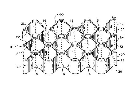
DETAILED DESCRIPTION OF T~IE DRAWI~lGS
AND PREFERRED EMBODIMENT O _T~IE I_VENTION
FIG. l depicts a wall beill-J cons-tructed with
stackable soil confinement grid material 10 of the
.
-- 3
~5~
-- 4 --
preferred embodiment of t~e present invention. The
grid material lO is comprised of a plurality of strips
of plastic 20 which are bonded toyether, one s-trip to
the next, at alterna-tinc3 ancl eclually spaced bonding
areas.
In the preferred embodiment of the present
invention, shown in more detail in FIG. 2, each layer
of grid material 10 is made of an even number of
uniformly wide plastic strips 20 in side by side
relationship, bonded by ultrasonic welding. The
preferred inside strips 22 differ in their notched
pattern from the outside strips 24, as more fully
described hereafter. The bonding between strips may
best be described by thinking of the strips as being
paired, startiny with an outside strip 24 paired to an
outermost inside strip 22, a pair of the next two
inside strips 22, etc. Each such pair is bonded at a
bonding area constituting an outside weld 32 adjacen-t
the end 34 of each strip 20. A short tail 36 between
the end 34 of the strip 20 and tlle outside weld 32 is
provided to stabilize segments of the strip 20 adjacent
the outside wel.d 32. Each pair of strips is welded
together at additional bondiny areas 14, creating equal
length strip segments between the ou-tside welds 32.
In addition to these welds, one strip 20 from
each adjacent pair of strips is also welded togetller at
positions intermedia-te each of the welds in the pairs
of strips, referred -to helea~teL as noll-pair bondintJ
areas 16. As a result, when the plurality of strips 20
are stre-tched in a direction perpendicular to the faces
of -the strips, the plastic strips bellcl in a sinusoidal
manner and forms a grid of cells ~L0 in a repeating cell
pattern.
Each cell ~L0 has two cell walls made from one
strip 20 and two cell walls made from a differellt stlip
20.
-- 4
3~
In -this configuration, it is seen that the
end sec~ion of each s-trip 20 forms one wall of a cell
on the perimeter of the grid material 10. In addition,
the outside s-trips 24 form cell walls all lying on the
perimeter of the c3rid material. When several layers of
grid materials 10 are stacked on top of one another,
it is -the open tops and bo-ttoms of these perimeter cells
which are exposed if each cell above and below is not
directly aligned.
In the preferred embodiment of the present
inven-tion, the`lowermost or base grid material 12 of a
stack is designed to rest on a flat surface. (FIG. 1.)
Since it has no yrid layer 10 below it with which it
needs to align, the bottom structure of each strip 20
in the base layer 12 is uniformly even. However, in
many instances a grid layer lO with notched bottom
corners would be suitable as the bottom layer of a
stack. In the preferred embodiment the inside strips
26 and outside strips 28 of a special base layer 12
differ rom one another just as the inside strips 22
and outside strips 24 differ from one another.
Figures 3-6 respectively are plan views of the inside
and outside strips 22, 24, 26 and 28, showing -the pre-
ferred shapes of these strips.
The inside strip 22 (FIG. 3) used for most
grid layers has a central section 42 which is notched
inwardly such that it is a predetermined distance below
the upstanding edge section ~ acljacent the ends 34 of
the strip 22. The celltral notched section ~2 extends
just beyond the region o -the ou-termost non-pair bond-
ing area 16.
In the preferred elnbodimellt, the bondillc3
areas 14 are about 13 inclles apar-t on each strip, as
are the noll-pair boncling areas 16. Since the non-pair
bolldillc3 areas 16 are intermediate the building areas
14, each cell wall comprises a sec-tion of the plastic
-- 5
-- 6 --
strip about 6~2 inches in length, between the alt~r-
nating bonding areas 1~ and non~pair bonding areas 16.
The tail 36 is about 1 inch in length. The central
notched section begins about 5~ inches from one outside
weld 32 of the strip 22 and runs to a point about 5
inches from the other outside weld 32. Since the
outermost non-pair bonding area 16 is about 6~ inches
from the ou-tside weld 32, -this central section 42
extends about 1 inch past the outermost non-pair
bonding area 16 on each half of the strip 22.
The bottom edge of each strip 22 is also
notched inwardly in its end sec-tion adjacent each
outside weld 32 (at each bottom corner). This results
in a central section 46 descending below the level of
the notched corner areas 48. The distance between the
levels of section 46 and corner areas 48 i~ approxi-
mately equal to the predetermined distance between the
height of the top central section 42 ~nd u~standi~g
section 44. In -the preferred embodim2nt, this predeter-
mined distance is about 1/2 inch. The length oE thenotch in the corner areas 48 is about 2~ inches, which
is slightly lonyer than the ~ail 36, extencling about 1
inches insicle of the outside weld 32.
As seen in FIG. 4, the outside strip 2'L ~as
an unno-tched uniformly e~len top edge bu-t includes
notches in its bottom corner areas 48 wllich are identical
to the notches in corner areas 48 of inside strip 22.
As shown .in FIGS. 5 ~nd 6, strips 26 and 2~ are respec-
tively identical to strips 22 and 24 except that ~as
mentioned previously) the bottom edges of strips 26 and
28 are ullllotched and uniormly even over the lengtll oE
each strip.
After beincJ welded tocJether, the plastic
s-trips 20 oE the preferred embodiment of the invention
tend to retain a linear shape. Tllis allows the grid
material 10 to be easily shipped, stored and halldled
-- 6 --
- 7 ~ 7
until it is used to make a wall or other struc-ture.
The preferred method o constructing walls ~as shown in
FIG. 1) is to anchor guidinc3 posts 18 in-to the c3round
at the corner positions where -the wall is to be built.
The base layer grid material 12 is nex-t s-tretched out
and the corner cells are slid clown over the posts 18.
Soil (such as sand or any other readily accessible and
suitable fill material) is next filled into the cells
40 of the base layer grid material 12 and compacted (if
desired). A grid layer 10 is then stretched out and
slid down over the posts 18.
In this position, and as shown in FIGS. 7 and
8, the notches in the bottom of this second layer and
the notches in the top of the base layer cooperate so
that in the central section of the grid, the cell wall
material of the top layer rests on the cell wall
material of the bottom layer. In these internal areas,
alignment of the cells is not critical. On the
perimeters of the grid, however, the downwardly
extending central sections 46 of the strips 22 and 24
of grid layer 10 contact the top edge of outside strips
28 along its entire length, and the upstanding edge
sections 44 of the inside strips 26 for a distance of
about 4 inches. In order -to get the second layer to
nest properly, the flexible plastic of the strip must
be slightly deformed so that the interfering areas
become overlappincJ areas, the portions of cell wall
material on the base layer 12 beinc3 outside the
portions from the second layer of grid material 10.
(See ~IG. 9) ~ecause of the notches in the bottom
edges, the perimeter corners of perime-ter cells cross
over the upstandincJ sections 44 of the lower layer of
grid material. After placement, the second layer is
then filled with soil, and the process is repeated,
s-tackincJ as many layers of grid materia:l 10 as
ecessary -to build the wall to desired lleicJIl-t.
-- 7
~35~ 3t~
In tlle preferred embodiment of the invention,
each plastic strip 20 is 8 inches wide. The yrid ma-
terials may be manufactul-ed to result in grids of any
dimension, but are typically 3 to 8 fee-t wide and 8 to
20 feet in lenyth when stre~ched out for use. The pre-
ferred plastic is sheet extruded polyethylene, 50 mil
thick. Carbon black may be included to help prevent
ultraviolet degradation of the grid material exposed to
sunlight. The bonding may be accomplished by a number
of methods know~ in the art: The preferred method of
ultrasonic welding is accomplished using the process
and apparatus disclosed in U.S. Patent No. 4,647,325,
issued Marc~l 3, 1987 to Gary Bach
The bond is formed by groups of
welding tips simultaneously contacting the strips 20,
the weld thus substantially traversing the entire width
of the strips 20.
Tlle design of the preferred embodiment pro-
vides two features which help to keep soil or other
fill material in perimeter cells from escaping from
stacked grid structures. First, the overlap on the
cell walls on the perimeter of the grid is useful to
align the cells during stackin~. By nesting the walls
of the top cells into the bottom cells, the perimeter
cells are easily aligned and stay in alignment during.
the process of filling the cells with soil. Second,
the overlap creates a barrier ayainst soil particles
leakiny out between layers-of aligned cell walls.
The invelltion provides a cJrid material which
can be used to form walls UsillCJ locally available fill,
such as soil, in a simple, guick and unexpensive
fas]lion, but which have minimal loss o~ soil material
from the perimeter cell walls. This is especially
useful in situati~ns wllere very dLy, fi!ld yranular soil
such as sand is used. ~lit]l t]le present invention it is
conceivable ~o build "sand ]louses" in desert terraiIl,
like sod llouses of early prairie pioneer clays.
, .. ~
.3'~
g
Of course it should be understood that a wide
range of changes and modifications can be made to the
preferred embocliment described above. For example, if
overlapping and ali~nment is neecled on only one surface
of a wall, no dis-tinct outside strips 24 and 28 would
be needed. Likewise, no special base layer 12 is
needed if the surface on which the wall is built is
soft enough so that downwardly extending bottom ed~e
sections 46 of strips 22 and 24 would sink into the
soft surface. Further, instead of having notched
inward central sections 42 on top of the strips 20 and
downwardly extending central sections 46 on bottom, the
two could be reversed. If the central section of
strips 22 extended above the end sections, then the
outside strips 24 and 28 would not need a notch in
their bottom corners, but would need a notch in the
bottom edge at each bonding area 14.
It is therefore intended that the foregoing
detailed description be regarded as illustrative rather
than limiting, and that it be understood that it is the
following claims, including all ecIuivalent, which are
intended to define the scope of the invention.