Note: Descriptions are shown in the official language in which they were submitted.
~Z~5232
IMPROV~SD C:URTAIN ROD ASSEMBLY
BACKGROUND ANI? DISC~JS5ION OF THE INVENIION
The present invention relate~ to curtain rods,
5 e~pecially those used ~n connec~ion with vertical blinds
and hand drawn curtain~, as well as other curtain mean~.
Contemporary curtain rod as~emblies are
functlonal in that they enable the curtAins or bli~ds
hanging thereon to be supported ln a window Rnd permit the
curtains or bllnds to be drawn open or closed. However,
such curtain rods generally are ~ot ~esthet~cally
plessing.
Attempts to improve the ~thetic appeal of
curtain rods have been only ~arginally successul.
Ganerally, such curtain rods are expensive ~nd their
a~sembly i~ ~xtremely tlme consuming. Others sacri~ice
functlonallty for aesthetlc appeal.
It would be useful to ~8 abl~ to provide a
curtaln rod a~sembly sxhi~iting the charactori~ticE of
~0 ~aso o~ a~embly, ~ecthetic appeal, whil~ ma$ntainin~ ~ull
functionality.
The invention described herein overcom~ the
pro~lems noted above by providing a functional~system with
ao~thetic appeal. According t~ the pre~ent invention, a
curtain rod includes ~ track on which curtains or other
curtain means, such a~ vertical blinds, are ~upported.
The track includes a fa~tener m~an6 for ~lidably receiving
or cli~ping ther~to ~ fasc~a member, whi~h ~part~
aestheti~ appeal to tbe ~urt~in rod assembly. The unigue
assembly further includes elbow members and ~ide f~cia
~embers to complement the ~esthetic nppeal o the
assembly. The fa3cia member~, which are 61idab1y
removable from the track, ~ay be provided in a variety of
., . i
.. ~
: ,
~;~9~32
colors or geometric ~hapes, enabling the user to change
the color or style of the curtain as~embly as reguired for
example when differently colored or differently styled
c~rtains are used.
The above has been a brief description of
certain problems in the prior art and advantages of the
invention. Other eatures will be apparent from the
Detailed Description of the Preferred Embodiment which
ollows.
BRIEF~DESCRIPTION OF-THE DRAWINGS
Figure 1 illustrates an ifiometric exploded view
of a preferred embodiment of the present invention.
Figure 2 illustrates a side view of a track
member and fascia member o~ a preferred embodiment of the
pre~ent invention.
Figure 3 illustrates a plan view of an elbow
means for use with a preferred embodiment of the present
invention.
Figure 4 illustrates a side Yiew of the elbow
means of Figure 3.
Figure 5 illustrates another side view of the
elbow means illustrated in Figure 3.
6-~ Figure 6 illustrates a ~ection taken along lines
~ of Figure 4.
Fi~ure 7 i~u~trat~s a side view of ~ return
means for w e with a preerred embodiment of the pro~ent
lnvention.
Figure 8 illustrates a top view of a return
means illustrated in Figure 7.
, . :
.. . .
~Z~5~:3Z
--3--
Figure 9 illustrates a rear view of the return
means illustrated in Figura 7.
Figure 10 illustrates 8 front view of a socket
maans used with a preferred embodiment of the present
invention.
Figu~e 11 illustrates a sec~ional view taken
along lines~ of Figure 10.
Figure 12 illustrates a side view of the socket
means illustrated in Figure 10.
Figure 13 illustrates a i~ometric exploded view
of another preferred embodiment of the present invention.
DETAILED DESCRIPTION OF THE INVENTION
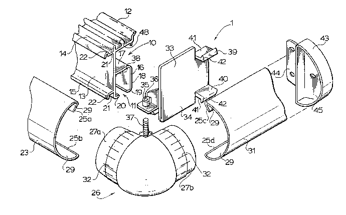
As illustrated in Figure 1, a curtain rod
a~sembly 1, includes a track 10, which may be, for example
a hand traverse cirmosa with baton draw, or a vertical
blind fascia track. The track 10 is preferably fabricated
of extruded aluminum, or other extrudable material, a~d,
a~ illustrated in Figure 1, i5 a hand traverse cirmosa
with baton draw. The tracX 10 has a slotted ~ection 11
for r~ceiving rollers, such a3 tho~e disclosed in U.S.
Patent No. 3,076,222, or other mean~ for hanging curtains
on the track.
The track 10 preferably includes a rlbbed header
portion 12, which provides ~trength and assi~ts the track
in resisting deformation when loaded. A vertical wall
member 13 on track 1~ extend~ vertically from slotted
section 11, and doubles as the front wall therefore, to
ribbed header portion 12. The xemainder oi ~lotted
section 11 is defined ~y an angle~ ~ection 16 extending
rearwardly from the ~ertical wa$1 member 13 and having a
top portion 17, and a rear portion 18. A rear lip 19 and
front lip 20 are al50 defined by slotted section 11.
..
`"' ~, .
" '. '
~2~32
Rollers (not ~hown) for hanging curtains are supported by
the rear and front lips 19 and 20 and travel along the
slotted section 11.
The vertical wall member 13 preferably further
S includes an upper flange 14 and a lower flange 15
extending outwardly from the vertical wall member 13 as
indicated. The upper and lower flanges 14 and 15 each
preferably include a grooved portion 21 bounded on the
outward edge of the flanges 14 and 15 by a curbed portion
2~
The present invention further include a fascia
member 23 a preferred embodiment of which, as more clearly
illustrated in Figure 2, comprises a ~emicircular external
wall ~ection 24 and two inwardly extending (upper and
lower) clip portions 25. Clip portions 25 of fascia 23
form an acute angle "A" of 39 24' with the semicircular
external wall section 24, although other angles are
acceptable. Additionally, wall section 24 need not be
semicircular, as other geometric shapes could be used.
The clip portions 25 are designed such that the
fascia 23 is slidably received by or clipped to track 10.
Specifically, the clip portions 25 travel in the grooved
portions 21 of the track 10 as illustrated, the upper clip
portion 25a traveling in the grooved portion 21 of the
upper flange 1~, and the lower clip portion 25b traveling
~n the grooved portion 21 of the lower flange 15. The
curved portions 22 retain the clip portions 25 of the
ascia 23 in slidable engagement with track 10.
The fascia 23 i~ preferably ~abricated of a
durable, yet decorative material, such as rolled steel or
high strength pla~tic. In a preferred ombod~ment of the
invention, the fa~cia 1~ fnbricated o~ rollod Jt~el which
i8 coated with a colored decorative re~lective coating.
The fascia 23 i8 primarily a decorative component of the
invention, serving to ~over the le~s attractive track 10.
However, the fascia 23 does impart a de~ree of deflection
resistance to the overall curtain rod structure.
, ~ :
, : .
~29~i23~
-
--5--
As illustrated in Figure 1 and Figures 3-6, the
present invention also preferably includes an elbow member
26 which is preferably constructed of high impac~ styrene
or other material~ ~uch as brass, wood and the like. It
includes a 90 bent portion 30 from which extend two male
couplings 27. The male couplings 27 preferably include a
tapered section 28, which for example may be formed by
putting a chamer 28 on the male coupling 27 as
illustrated in Figures 4 and 6. One of ~he male couplings
27a is slidably received by one end of the fascia 23, the
outer shape of the male coupling 27 conforming to the
inside configuration of the fascia 23. The male coupling
27 is inserted into the spaces 29 formed by the
~emicircular section 24 and the clip por~ion6 25 of the
fascia 23.
The other male coupling 27b i8 adapted to be
inRarted in a s~de fascia 31 a~ illu~trated in Figure 1.
The side fascia 31 has clip portion# 25 similar to the
~ascia 23, and similarly ha~ spaces 29 into which the
other male coupling 27b is inserted creating a tight fit.
As lllustrated, the male couplings 27 may be
supplied with peel ribs 32, which as~ist in creating the
tight fit batween the male coupling~ 27 and the ~ascia 23
and side fascia 31. In addition to coupling the fascia 23
2S to thQ ~ide ~ascia 31, the elbow member 26 provides a
~mooth, fini~hed appearanco to the corner of the curtain
rod assembly. Typically, there are two ~uch elbow
members 26, one at either end of the fa6cia 23, connecting
two side fascias 31 to the fascia 23.
3l
The ~lde faccia~ in turn, are connected to
the track 10 by a connecting means 33, ~uch a~ a univor~al
return plate. The return plate 33 ~as 8 face plate 34 to
which is attached an attachment flange 35. The attachment
flange 35 illu~trated in Figure 1 includes a hole 36 for
raceiving a fastener, such as a ~crew 37. The return
plate 33 is attached to the track 10 by placing the
attachment fl~nge 35 inside the 6pace 38 of the slotted
~2~3~
section 11 and inserting the screw 37 through the hole 36.
The head of the screw 36 is then tightened against the
rear and front lips 19 and 20.
The return plate 33 alss includes an upper
flange 39 and a lower flange 40 extending outwardly from
the faceplate 34. Like the upper and lower flanges 14 and
15 of the track 10, the upper and lower flanges 39 and 40
of the return plate 33 have a grooved portion 41 adjacent
the face plate 34 and a curbed portion 42 adjacent the
grooved portion 41. The upper and lower flanges 39 and 40
are preferably splayed at a sliqht outward angle with
respect to each other. An angle of about 5 with respect
to a line normal to the face plate 34 as illustrated in
Figure 7 has proven satisfactory.
The clip portions 25c and 25d of the side fascia
31 are clipped respectively to upper and lower flanges 39
and 40 of the return plate 33, in much the same manner as
the clip portions 25a and 25b of the fascia 23 are
slidably received by or clipped to the upper and lower
flanges 14 and 15 of the track 10. The clip portions 25
of the side fascia 31 are slidably received by the grooved
portions 41, and the side fascia is retained in slidable
engaqement with the return plate 33 by the curbed portions
42.
The side fascia 31 is preferably constructed of
the same material as the fascia 23. Tha side fascia is
thus a decorative facing which serves to cover the less
aesthetically pleasing functional components of the
curtain rod assembly. In addition, the side fascia 31
serves, at least in part, as a means of attaching the
curtain rod assemb7y ~o a w~ll. In this regard, as
illustrated in Figure 1, the side fascia- 31 -may be
inserted into a wall socket 43. The wall socket 43 has
means 44 for fastening the wall socket 43 to a wall, such
as a flange with screw holes therein. Additionally, the
wall socket 43 has a receptacle 45 sized and shaped to
permit slidable insertion of the side fascia 31 therein.
.. ., .. - . .
~L2~5~32
Preferably, the side fas~ia 31 i8 sized to fit snugly into
the receptacle 45, obviating the need for other fasteners
or adhesiva means, which of course, could be employed.
For example, as illu~trated in Figure~ 10-12,
the wall socket ~3 may include one or more posts 46
positioned around the perimeter of the receptacle 45,
spaced from the receptacle wall 47 to on~ble the Ride
fascia to be held 6ecurely between the posts 46 and the
receptacle wall 47. In addition to or in place of wall
sockets, the curtain assembly may be attached to a wall
with conventional attachment meanC not shown.
The wall socket is preferably manufactured of
high impact styrene, which has been coated with a coating
matching that of the fascia 23 and side fascias 31.
The return plate 33 is preferably po~itioned
flu~h against the end 48 of the track 10, cuch that the
~ace plate 34 abut the end 48 of the track 10.
An alternative preferred embodiment of the
present invention i6 illustrated in Figure 13. In thi~
embodiment, the track 10 is adapted for use with vertical
blinds. In the Figure 13 embodiment, a vertical blind
rotating mechanism 49 is positioned at the end 43 of the
track 10 and secured thereto. A modified return plate 33
~8 then attached to the rotating mechanism 49, for
2S example, with screws S0, which are passed through holes Sl
tn the face 34 of the return plate 33.
Preferably, the assembly i8 con~tructed such
that the elbow 26 i~ a right angle bend imparting a right
angle relationsh~p between the f~scia and ~ide fa~cia~.
Of cour~e, other angles ~re possible.
",.~. .
"~..... ' . ',