Note: Descriptions are shown in the official language in which they were submitted.
'~ O
B~CKGROUND OF THE INVENTION
The present invention relates generally to methods
and apparatus for measuring deviations from flatness on a
horizontal surface, and more particularly to methods and
apparatus for doing so with improved speed and accuracy.
There are a number of instances where the flatness
of a horizontal surface is a matter of critical importance.
Examples of such instances include floors in warehouses
having high storage racks. In warehouses of this type, goods
are moved to and from the storage racks by fork-lift trucks
having lifting forks mounted for vertical movement on
vertical frames extending as high as 40 feet above the floor,
for example. As these trucks move across the floor,
deviations in floor flatness are manifest by vibrations or
oscillations in the vertical frame, and the amplitude of
these oscillations increases with the height of the frame.
These oscillations are undesirable, and accordingly, flatness
tolerances on the floors in such warehouses are extremely
strict. If the flatness deviations are outside these
tolerances, the floor must be refinished to bring flatness
within the tolerances.
Flatness deviations comprise bumps and recesses,
and these are defined by (a) slope (i.e. the angle from the
horizontal), (b) vertical displacement from a given reference
level and (c) curvature (cha~nge of slope). In order to
determine whether floor flatness is within tolerance, it is
necessary to measure the flatness of th~ entire floor, and
this requires a multiplicity of flatness measurements at
relatively closely spaced intervals in two mutually
3~ perpendicular directions and encompassing the entire area of
the floor. There are a number of types of measuring devices
previously employed for thi~ purpose, but they all have
drawbacks of one type or another.
420
There are manual systems for measuring flatness
deviations, and these usually employ a traditional engineer's
optical level and rod or a level straight edge with a sliding
dial gage mounted at right angles to the straight edge.
Measurements obtained from these manual systems are then
graphically plotted on a grid of the floor. These systems
are tedious, labor intensive and often require skilled
personnel. Another drawback is that the time constraints
associated with these manual systems limit the number of
actual measurements to a relatively small number of points on
the floor, and this requires interpolation from the actual
measurements to reflect flatness deviations between the
measurement points. Interpolation does not necessarily
provide a true indication of flatness deviations between
measurement points. In floors requiring the critical
flatness characteristics under discussion here, such
interpolations are not acceptable.
Reducing the interval at which the above-described
manual measurements are made, to the extent necessary to
avoid unacceptable amounts of interpolation, makes the entire
measurement job extremely lengthy, tedious and expensive.
Another manual method for measuring flatness
deviations employs a device which is moved across the floor
along a line on a step by step basis. At each step an
- instrument mounted on the device gives a reading of slope or
displacement. This procedure is repeated along a
multiplicity of spaced lines on the floor, and the readings
at each step on each line are recorded and plotted. This
procedure too is tedious and time consuming.
Other flatness measurement devices employ wheeled
vehicles mounting instruments which measure floor slope as
the wheeled vehicle moves across the floor along a
predetermined line. This procedure is repeated along a
-- 2 --
~5~20
multiplicity of spaced lines. Measurements obtained from the
slope sensing device can be recorded and plotted. ~lthough
this procedure is less tedious and less labor intensive than
the manual procedures described above, there are distortions
in the data produced by such a procedure in that the slope
measurement produced for a given floor location may not
accurately reflect the actual slope at that location, and the
curvature and displacement data provided by such a procedure
are also not accurate.
SUMMARY OF THE INVENTION
The present invention provides a method and
apparatus for automatically measuring flatness as a wheeled
vehicle follows a line along a floor or other horizontal
surface, and it does so while eliminating or minimizing the
distortions inherent in prior art procedures of this type.
The slope measuring instrument utilized in the
apparatus is an inclinometer, a conventional, commercially
available slope sensing device. The inclinometer is mounted
on a trailer or similar vehicle having front and rear
wheels. The inclinometer generates a voltage signal which is
proportional to the angle of the slope it senses.
The inclinometer is sensitive not only to slope but
also to acceleration. The apparatus moves along the floor at
a constant driven speed, but when the apparatus is started
from a dead stop, it accelerates from zero to the constant
; driven speed. Accordingly, slope measurement readings are
not begun until some time after the start, when the apparatus
is traveling at a constant driven speed. Otherwise, voltage
; 30 signals generated by the inclinometer would be influenced bythe acceleration from a dead stop, and the signals would not
accurately represent the slope along that portion of the
floor at which the device is accelerating.
- 3 -
12~5~20
The slope sensing device (i.e. the inclinometer) is
first calibrated and then run at a constant driven speed on
the floor surface along an elongated path having a
predetermined length and a pair of parallel side edges. As
the device is run along the path, measurements are
continuously made of the slope of the floor surface in the
longitudinal direction of the path, along at least one side
edge thereof and preferably along both side edges thereof
using an inclinometer along each side edge. Measurements are
also made transversely across the path using another
inclinometer. A continuous voltage signal is generated for
each of the longitudinal and transverse continuous slope
measurements. Each of these continuous voltage signals is
recorded as continuous raw analog slope data. The analog
slope data is then digitized at a pre-selected digitization
interval to thereby produce raw digital slope data which is
then converted to calibrated digital slope data.
The digitization interval is introduced into the
slope data after producing raw analog slope data as a
continuous signal. As a result, the digitization interval
can be custom selected for each particular job, and there are
no constraints in the apparatus itself on the digitization
. interval. By selecting a digitization interval which is
; sufficiently small, one can minimize the distortion otherwise
~- resulting from converting continuous analog data to digital
` form.
As noted above, the inclinometer which measures the
slope along the longitudinal direction of the path i9 located
on a trailer having front and rear wheels. In such an
arrangement, the voltage signal generated by the inclinometer
reflects a slope location which lags the actual slope
location by one-half the distance between (a) the axis of the
front wheel and (b) the axis of the rear wheel. The present
-- 4 --
~z~s~o
invention employs a procedure, to be subsequently described,
for overcoming the distortion resulting from this lag.
The present invention includes other procedures, to
be described below, for correcting distortions or errors
otherwise introduced into the data by measurement methods of
the general type employed herein.
The method and apparatus of the present invention
are not limited to measuring the flatness of warehouse floors
or the like but also have other uses such as determining the
location of beams in floors, determining where a floor has
been deformed due to overloading, determining the presence of
curling or uplift at certain joints in a floor, and other
uses of a forensic nature.
Other features and advantages are inherent in the
method and apparatus claimed and disclosed or will become
apparent to those skilled in the art from the following
detailed description in conjunction with the accompanying
diagrammatic drawings.
BRIEF DESCRIPTION OF THE DRAWINGS
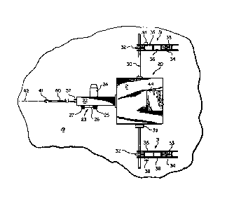
Fig. 1 is a plan view of an embodiment of apparatus
constructed in accordance with the present invention;
Fig. 2 is a side elevational view of the apparatus
of Fig. l;
Fig. 3 is a block diagram illustrating a portion of
the apparatus;
Fig. 4 is a flow diagram reflecting data processing
in accordance with the present invention;
Fig. 5 (on sheet 2) is a diagrammatic illustration
of calibration structure;
Fig. 6 (on sheet 2) is a graph illustrating a
calibration curve employed in connection with the present
invention;
lZ~54~0
Fig. 7 ~on sheet 1) illustrates diagrammatically
the distortion phenomenon known as phase lag; and
Fig. 8 is a diagrammatic illustration of another
embodiment of a method and apparatus in accordance with the
present invention.
DETAILED DESCRIPTION
Referring initially to Figs. 1 and 2, illustrated
generally at 20 is an apparatus for measurin~ deviations from
flatness on a horizontal surface, such as a floor surface
19. Apparatus 20 is constructed in accordance with an
embodiment of the present invention and comprises a housing
21 containing circuitry and controls for the apparatus.
Extending forwardly from housing 21 is a member 22 beneath
which is located an apparatus driving mechanism indicated
generally at 23. Mechanism 23 comprises a D.C. motor 24
driving a first sprocket 25 in turn driving a chain 26 in
turn driving a second sprocket 27 drivingly connected to the
axle of a drive wheel 28.
Located beneath housing 21 is a transverse axle 30
- at each opposite end portion of which is located a wheeled
'~ .
trailer indicated generally at 31. Each trailer 31 comprises
a front wheel 32 mounted on axle 30 and spaced from a rear
wheel 33 mounted on an axle 34 extending between a pair of
side plates 35, 36. Mounted on the outer side plate of each
trailer 31 is an inclinometer 38, and mounted on transverse
, ~,,
axle 30 adjacent housing 21 is an inclinometer 39.
~,~ Inclinometers 38, 39 constitute instruments for measuring
: - ~
`~ slope and are of conventional construction and commercially
-~ 30 available. Each inclinometer 38, 39 is sensitive to both
;~ slope and acceleration.
Each inclinometer 38 is mounted on trailer 31
between front wheel 32 and rear wheel 33. The location of
- 6 -
~95~2~
rear wheel 33 and its axle 34 may be adjusted to vary the
distance between axles 30 and 34. Thus rear axle 34 may be
adjusted to locations indicated at 34at 34b or 34c in Fig. 2.
Extending forwardly from drive mechanism 23, and
pivotally connected thereto at 37, is a guide arm 40 at the
forward end of which is a hook 41 for engaging a guide line
42 composed of string or cord. Guide line 42 defines an
elongated path along which apparatus 20 moves for the purpose
of measuring the floor flatness. Guide line 42 starts at a
location upstream of the location where flatness measurements
begin and extends downstream past the location where flatness
measurements end, for a distance equal to at least the
distance between the rearmost inclinometer and hook 41.
Located atop housing 21 is an analog recorder 44 of
conventional construction.
Referring to Fig. 3, drive motor 24 is powered by
batteries 46 delivering D.C. power to motor 24 through a
voltage regulator 47 which provides a constant voltage to
assure that drive motor 24 operates at a constant drive speed
thereby moving apparatus 20 along the measurement path at a
constant driven speed. The speed of the apparatus is
determined by timing the apparatus as it runs the length of
the path after the latter has been determined and measured.
The test for speed is repeated many times (e.g. ten times) at
- the start of each project, and the results are averaged to
give an apparatus speed which is used for data purposes.
The measurement path has a predetermined length
having opposite ends located as close as possible to the
opposite ends of the floor, consistent with constraints to be
subsequently described. The path has a pair of parallel side
edges along which trailers 31, 31 travel.
As a preliminary step of the measuring procedure,
inclinometers 38, 39 are calibrated employing a technique to
~29s~
be subsequently described, followed by the performance of
other steps including running apparatus 20, with its
calibrated slope sensing devices 38, 39 at a constant drive
speed on floor surface 19 along the aforementioned path.
As apparatus 20 moves along the path, there is a
continuous measurement of the slope on the floor surface
along the path, in the longitudinal direction of the path,
along each side edge thereof by inclinometers 38, 38 and
transversely across the path by inclinometer 39. Each
inclinometer generates a continuous voltage signal
corresponding to each of the two lon~itudinal and one
transverse continuous slope measurements. Each of these
continuous voltage signals is filtered, for reasons described
below, to remove extraneous high frequency voltage signals,
to thereby produce continuous raw analog slope data.
The inclinometer is sensitive not only to slope and
acceleration, but also to very small, extraneous surface
irregularities, such as a sand particle or the like, which
are not manifestations of deviations from a level surface.
The voltage signals caused by the sensing of these extraneous
irregularities constitute noise making it difficult to detect
the true slope employing voltage signals direct from the
inclinometer. However, voltage signals reflecting extraneous
irregularities have a much higher frequency than voltage
:
signals reflecting slope. Accordingly, the voltage signals
.
generated by the inclinometer are subjected to a filtering
-, ~
step which filters out the extraneous high frequency voltage
`, ~ signals so that the resulting continuous raw analog data
reflects only continuous analog slope data.
` 30 Referring now to Fig. 3, a battery 50 supplies D.C.
- power to inclinometers 38, 38 and 39 and to a filter 51 which
removes, from the continuous voltage signals originating at
the inclinometers, the extraneous high frequency voltage
- 8 -
signals. The filtering step removes high frequency "noise"
from the inclinometer, no matter the source. The unfiltered
low frequency voltage signals constituting the output from
filter 51 more accurately reflect the floor slope sensed by
the inclinometer. As used herein the expression "extraneous
high frequency" refers to frequencies which reflect very
small, extraneous surface irregularities and other "noise".
The frequency level at which filtration occurs is
dependent upon the speed at which the inclinometer moves
along the measurement path, and this frequency level is
determined empirically. For example, in a given project,
surface irregulatories having a length less than 2 in. (50.8
mm) may be of no importance. For a given speed, the
frequency of voltage signals reflecting a selected
irregularity length can be determined. For example, at a
speed of 4 in./sec. (102 mm/sec.), a voltage signal frequency
of 2 hertz may correspond to an irregularity length of 2
in.(50.8 mm), and shorter irregularity lengths will be
reflected by higher frequencies. Accordingly, in the given
example, filter 51 can be manually adjusted with a dial (or
set of dials) 51a to filter out all frequencies above 2
hertz, and this will filter out all signals reflecting
irregularity lengths less than 2 in.(50.8 mm) as well as
other noise above the selected frequency.
~` If there is a dramatic change in the speed at which
trailer 31 moves, e.g. if the speed is doubled, filter 51
would require adjustment at dial 51a with respect to the
frequency at which voltage signals are filtered. The
adjustment would be preceded by a filtration frequency level
determination of the type described in the preceding
paragraph, because at the changed speed, 2 hertz would no
longer reflect an irregularity length of 2 inches (50.8
mm). Provision for manual adjustments in the frequency at
12~20
which filtration occurs is a common expedient in filters and
is well within the skill of the art given the information set
forth above.
Each of the inclinometers 38, 38, 39 is
electrically connected by lines 43, 45, 48 to a gang switch
at 52 which can be thrown to connect each of the
inclinometers to ground at 53. The inclinometers are
grounded out while the drive motor is accelerating from dead
stop to a constant driving speed. This is a time during
which the inclinometers would generate voltage signals
reflecting acceleration. Hence the grounding out of the
inclinometers during this time period. The starting point of
the measuring path is selected to be sufficiently downstream
of the dead stop location (e.g. several feet) to give the
drive motor a chance to develop a constant driving speed.
When apparatus 20 reaches the starting point of the
measurement path, gang switch 52 is thrown in an opposite
direction from ground, thereby electrically connecting the
inclinometers to filter 51 via lines 54, 55, 56. Filter 51
is electrically connected by lines 57, 58, 59 to analog
recorder 44. Raw analog slope data is continuously generated
between the beginning and the end of the predetermined
flatness measurement path, and that data is recorded at
' analog recorder 44.
Subsequently, analog recorder 44 is electrically
connected by lines 60, 61, 62 to a digitizer 63 for
~ converting the raw digital slope data to calibrated digital
`~ slope data for each of the three measured slopes. Filter Sl,
'~ analog recorder 44 and digitizer 63 are of conventional
construction or are within the skill of the art given the
information set forth above, and the details of these
` components do not constitute part of this invention.
:
-- 10 --
;420
Referring now to Fig. 4, the output from digitizer
63 is raw digital slope data which i5 fed into a computer, of
conventional construction, where the raw digital slope data
is converted to calibrated digital slope data (73) which in
turn is used as a basis for computing displacement and
curvature (74), employing conventional computing techniques.
The method steps for calibrating the slope sensing
devices 38, 39 and for converting raw digital slope data into
calibrated slope data will now be described, with reference
to Fig. 5. Indicated generally at 66 is a calibration block
comprising a base member 68 and an adjustable member 69
having a top calibration surface 64. The front and rear
wheels 32, 33 of each trailer 31 are placed on calibration
surface 64 which can be adjusted to a plurality of known
longitudinal slope settings which can be confirmed by a
digital machinist's level 65, of conventional construction
and commercially available, placed atop trailer 31. The
calibration block may employ a screw adjustment at 67 to
obtain a desired longitudinal slope setting. Readings from
the digital machinist's level are observed for each slope
setting to which calibration surface 64 is adjusted, and the
readings are manually recorded as known slope settings.
Transverse slope settings are obtained by raising
one trailer 31 above the other, employing a pair of
adjustable calibration blocks, one block under each trailer
31. The calibration block under one trailer is as shown at
66. The calibration block under the other trailer differs
from block 66 in that the other block has a screw adjustment
not only at 67, but also at the front end of the block for
making adjustments to obtain desired transverse slope
settings. The steps employed for calibrating transverse
slope are similar to those described above for calibrating
longitudinal slope. When calibrating transverse slope, the
digital machinist's level is placed atop inclinometer 39, or
thereabouts.
Typically, the calibration procedure employs three
known slope settings for each inclinometer, e.g. a setting at
or about 0 slope, at or about 0.03 inches per foot positive
slope and at the same amount of negative slope. For a
longitudinal slope measuring inclinometer 38, a positive
slope is uphill in the direction of movement or uphill from
right to left in Fig. 2, and a negative slope is downhill in
the direction of movement or downhill from right to left in
Fig. 2. For transverse inclinometer 39, a positive slope is
uphill from right to left, as viewed from the front of the
apparatus (to the left in Figs. 1 and 2), and a negative
slope is downhill from right to left. At each known slope
setting, analog calibration data is produced by generating a
continuous voltage signal from each inclinometer, for a
period of time which will produce a multiplicity of digital
calibration points at a pre-selected digitization interval.
The digitization interval may be 1 inch or a fraction of an
inch, and this will be discussed more fully below. The
analog calibration data is recorded at analog recorder 44.
The calibration step should be performed at the
. start of every project and also each time after power to the
inclinometers is turned off.
After all of the analog slope calibration data has
been recorded for each of the three known slope settings, for
each of the three inclinometers 38, 38, 39, the analog
calibration data is digitized at the pre-selected
digitization interval to produce digital calibration data
(63a in Fig. 4). The same digitization interval is used for
digitizing both calibration data and raw slope data.
The digital calibration data is fed into the
computer which computes calibration information at 75. More
- 12 -
5~
particularly, the computer is programmed to derive
mathematically a calibration curve (Fig. 6) by putting the
observed, known slope settings along the x coordinate for
this curve and plotting the corresponding digital calibration
data, for each of the known settings, along the y direction
for the curve. The result is a straight line calibration
curve defined by the equation y = ax + b wherein a and b are
constants, in this case calibration constants, with the
following values:
when x is 0, y = b
when x is 1, y = a + b
As noted above, a multiplicity of digital
calibration points were obtained for each of the three known
slope settings plotted along the x coordinate. This was
accomplished during the production of analog calibration data
by generating continuous voltage signals from each of the
inclinometers for a relatively long period of time (e.g. many
seconds). When divided by the speed at which apparatus 20 is
driven (e.g. 4 in./sec.), this would correspond to a path
length of many feet; and for a digitization interval of one
inch, a multiplicity of digital calibration points are thus
produced for each known slope setting. It is desirable to
have a multiplicity of such digital calibration points when
preparing the calibration curve. In this way, one may
compensate for any irregularities or deviations in the
voltage signals from which the digital calibration data was
prepared. Such irregularities or deviations in the voltage
signals would be due to "noise" in the inclinometers. A
large number of data points permits these irregularities to
be averaged out when plotting the calibration curve.
After the calibration curve has been derived, it is
stored temporarily in the computer (or on a storage element
such as a computer disk). Subsequently, the calibration
~29~4~
curve or, more accurately, the e~uation defining the
calibration curve, is employed mathematically to convert raw
digital slope data to calibrated digital slope data wherein
the values for the raw digital slope data are along the x
axis for the calibration curve (i.e. x in the equation) and
the values for the calibrated digital slope data are along
the y axis for the curve (i.e. y in the equation) (Fig. 6).
This is a conventional computer operation which the computer
is programmed to perform at 73. More particularly, having
derived the straight line calibration curve defined by the
equation y = ax + b, and having determined the curve's two
calibration constants, a and b, as described in the second
paragraph above, for each item of raw digital slope data, x,
the computer computes a corresponding item of calibrated
digital slope data, y, employing the equation y = ax + b
wherein a and b are now both known constants (having been
determined when the calibration curve was derived) and x is a
known item of raw digital slope data.
As noted above, the digitization interval is
introduced into the slope data at digitizer 63, and this
occurs after raw analog slope data has been produced as a
continuous signal. Similarly, the digitization interval is
introduced into the digitizer after analog calibration data
has been produced as a continuous signal (63a). The
advantage of introducing the digitization interval into the
data after producing analog slope data as a continuous signal
is that the digitization interval can be made virtually as
small as possible, limited only by the storage capacity of
the computer, and the benefits of this are as follows. The
number of items of digital information is inversely
proportional to the size of the digitization interval. The
smaller the digitization interval, the more closely the
digital information reflects the continuous analog
- 14 -
~29~5`9s~ 20
information, without there being any gaps between the items
of digital information. In other words, the smaller the
digitization interval, the more accurate the digital data.
Therefore, selecting a digitization interval sufficiently
small minimizes the distortion otherwise resulting from
converting continuous analog data to digital form.
An error which must be avoided when carrying
inclinometer 38 on wheeled trailer 31 is a distortion in the
slope data due to phase lag. This occurs when trailer 31
first encounters a bump or depression in an otherwise flat
floor. Referring to Fig. 7, as front wheel 32 on trailer 31
begins to ascend (or descend) a slope 29, inclinometer 38
immediately begins to record the slope, but the rear wheel of
trailer 31 has not yet reached the slope. Consequently, the
slope signal produced by the inclinometer precedes or leads
the actual slope on the floor. It has been determined, in
accordance with the present invention, that for corrective
purposes, the slope signal's lead distance is one-half the
distance between the front and rear wheel axes of trailer 31
(i.e. the wheel base of trailer 31), and this parameter does
not change with a change in the location of the inclinometer
on trailer 31.
Therefore, in accordance with the present
invention, a correction is made for the distortion due to
phase lag by (a) measuring the distance between the front and
rear wheel axles of trailer 31, and then (b) shifting the
location, of each item of calibrated, digital slope data, in
a positive (+) direction along the x-coordinate on a graph
plotting amount of slope versus slope location. The extent
of the shift corresponds to the above-described measured
distance (i.e. one half the wheel base). For a wheel base of
2 inches, the amount of the shi~t would be 1 inch. Thus, if
a particular slope was shown, before the correction, to be at
- 15 -
0
a location 11 inches past the starting point of the measuring
path, after the correction that particular slope measurement
would be at 12 inches past the starting point.
As noted above, to avoid distortions in converting
continuous analog data to digital data, the digitization
interval is maintained relatively small. Typically, the
digitization interval is less than the distance between the
front and rear wheel axes of trailer 31.
In addition to slope data, it is desirable to
obtain other data characterizing the flatness deviations.
Such other data comprises displacement and curvature (rate of
slope change). Both displacement and curvature can be
computed from the slope data, and these computations are
performed at 75 ~Fig. 4) after converting raw slope data into
calibrated slope data. Displacement is computed by numerical
integration from the calibrated slope data, and curvature is
computed by numerical differentiation from the calibrated
slope data. The computer is programmed to perform these
computations employing conventional equations which are
within the skill of the art. Other, higher order derivatives
may be computed, if desired.
Another correction which must be introduced arises
in connection with the displacement data. When the
displacement data is computed by numerical integration from
digital slope data which in turn was converted from analog
slope data, there occurs an amplitude translation in the
displacement data for which there must be an adjustment
before the correct displacement is obtained.
The correction in the displacement data involves
measuring the elevation at both the beginning and the end of
the measurement path (e.g. with a transit), subtracting the
end elevation from the beginning elevation to produce an
elevation difference, and then incorporating this elevation
- 16 -
~:9~42~
difference into each item of displacement data to providecorrected displacement data. If the computed elevation
difference is a positive number, it is subtracted, and if it
is a negative number it is added to each item of displacement
data.
The resulting corrected displacement data can then
be numerically differentiated to produce slope data which
differ from the previously-obtained calibrated slope data
only in that very slight errors are now eliminated, but this
last step is optional. An additional optional step is to
determine, with a transit for example, the absolute elevation
and incorporate this figure into the displacement data as a
constant to give absolute displacement rather than relative
displacement.
Another distortion in the data can arise if there
is a substantial difference between the wheel base of trailer
31 and the length of the flatness deviation (e.g. a bump)
along the measurement path. When the ratio of (a) wheel base
to (b) length of flatness deviation is large, the measuring
device cannot accurately reproduce the true slope of the
flatness deviation. To the extent that correction for this
anomaly is possible, it can be accomplished by minimizing the
ratio of (a) the trailer's wheelbase to (b) the length of the
flatness deviations expected to be encountered, and this can
be done by minimizing the trailer's wheel base (a). Because
of physical constraints, it may be difficult to reduce the
; length of the wheel base to less than 2 inches. Typically, a
wheel base in the range 2-4 inches is employed in accordance
with the present invention, and this should be satisfactory
3~ for most operating conditions.
Referring to Fig. 4, after all the desired data has
been computed, it is presented in graphic form, either as a
tabular printout (77), or as graphs or curves (76) plotting a
- 17 -
12~
particular flatness deviation measurement (e.g. slope) versuslocation along the linear path at which measurements were
conducted. A summary report t78) can also be included as
part of the graphic presentation~ A conventional dot matrix
printer is employed to produce the graphic presentations
described in this paragraph.
In addition to being graphically presented as
printouts, the data can also be presented on the CRT screen
of the computer.
Data printouts or data presentations on the CRT
screen can also be obtained at various stages of the data
processing. This can be helpful in checking for aberrations,
which may be due to momentary voltage surges or the like; and
these aberrations can then be edited out of the data, if
desired.
Before the data is presented in graphic form, a
search is made (79) to determine the maximum and minimum
points within a particular specified quantitative range.
These points can reflect the limits on flatness devia~tions
contained in the project specifications, or other maximum and
minimum points can be selected as desired. The data can also
be checked (80) against the project specifications (81) which
are manually fed into the computer.
A primary reason for the search procedure is to set
limits for the graphs which are prepared, both the horizontal
(x) coordinate limits and the vertical (y) coordinate
limits. The specification limits can be plotted on the same
graph to show graphically when a flatness deviation is inside
or outside of the specifications. If, in the graph of one
particular set of data (e.g. slope), there is a part of the
graph which requires closer scrutiny, one may increase the
vertical scale and decrease the horizontal scale, on the
print-out of the graph.
- 18 -
12~54~
The computation and data processing steps described
above are performed by the computer which has been
appropriately programmed to do so. Such programs are well
within the skill of the art given the information set forth
above.
Acquired information (82) requiring a manual input
into the computer for each project includes, in addition to
the project specifications (81), the digitization interval,
the trailer wheel base, the length and width of the
measurement path, the known slope settings obtained during
the calibration operation, the phase lag dimension, the
displacement correction number (elevation differential), the
constant driven speed of the motor and the like. All of this
manual input information is required.
Optional manually input information (83) could
include the date on which the measurements were performed,
the location of the project, the names of the operators, and
the like.
After finally obtaining all the desired flatness
deviation data, and determining whether there are any
deviations which are outside the specification limits for the
floor's flatness, a refinishing step may be necessary to
remove, from the floor, at least some of the flatness
deviations. In the course of conducting this removing step,
one would employ at least some of the flatness deviation data
as a guide to direct the removing step. On a concrete floor,
flatness deviations in the form of bumps can be removed by
abrasion. On a concrete floor which has fully set, flatness
deviations in the form of recesses would be corrected by
removing that particular part of the floor, dictated by the
flatness deviation data, and applying fresh concrete to that
spot; and the same procedure can be applied to bumps.
-- 19 --
12~ 0
It is contemplated that a method in accordance with
the present invention can be performed not only on fully set
concrete, but also on incompletely set concrete. In the
latter situation, the removing step could be performed before
the concrete has fully set, and in such a case, all flatness
deviations, both bumps and recesses, can be corrected or
leveled out employing concrete finishing equipment.
Referring to Fig. 8, in a preferred embodiment of such an
operation, the concrete finishing equipment, shown
diagrammatically at 91, would follow or be coupled behind
measurement apparatus 20 along the measurement path and the
finishing equipment would be directed by signals, from a
computer 90 associated with the measuring apparatus,
continuously fed to the finishing equipment along a
communication cable 92.
The foregoing detailed description has been given
for clearness of understanding only, and no unnecessary
limitations should be understood therefrom, as modifications
will be obvious to those skilled in the art.
- 20 -