Note: Descriptions are shown in the official language in which they were submitted.
1~5a~4
21950-17
The present invention describes a process for the pro-
duction of a joint connection for rod frameworks having rigid
joints and having at least two rods that are connected to form a
joint, a metal casing having openings through which said rods
protrude and in which said rods end with a shape-locking, i.e.,
shaped or necked down, end section, being filled with hardenable
filling material.
Joint connections for rod framework having in excess of
two rods that are combined to form a joint are already known; in
these, the rods protrude through openings in a metal casing and
end in said casing in a shape locking, i.e., shaped or necked
down, end section, the metal casing being filled with a hardening
filling material.
In these known joint connections the filling material
consists either of a cement-bound concrete mortar or plastics,
with either pressure setting or thermo-setting plastics being used
for this purpose. Cement bonded concrete mortar hardens too slow-
ly, and the plastics that may be suitable entail the disadvantage
of relatively high cost and low temperature resistance. In
addition, it is necessary that the casing be filled completely in
order to achieve sufficient strength, and it is difficult to fill
the casing without any pockets being left in the filling material.
Various methods of producing a joint connection of the
type described are already known.
In the joint connection described in GB-PS 1 496 797 a
cement mortar consisting of sand and cement or a mixture of a
C34-4002-CApN
. -- 1 --
``` lZ9S4~4
21950-17
hardenable plastic and sand, is forced into the metal casing
optionally under pressure.
In the production of the joint connection described in
DE-~S 22 11 180 the rods are slid into the metal casing and the
remaining space within the casing is filled with a filler
material. Special concrete plastics, multi-component adhesives,
and the like are mentioned as being suitable molding materials.
In the joint connection described in SU-PS 947 331, the
hardenable mass is introduced lnto the cavity of the casing
w~thout the use of pressure. SU-PS 947 331 makes no mention of
the fact that a granulated solid is previously introduced into the
metal casing and that this is optionally compressed or prestressed
(preloaded). SU-PS 947 331 uses another method, in that is
proposes an expanding plastic mass for filling the metal casing.
It i8 an object of the present invention to describe a
process with which a joint connection for rod frameworks with
rigid joints, in particular for steel structures, can be produced,
this being possible with small expenditures of materials and which
is, in addition, simple, safe, and quick.
This object is achieved according to the present
invention by providing a process for forming a jolnt for
connecting at least three members of a frame structure in a metal
casing having a filllng aperture and openings therein receiving
positive-connection-forming end portions of the members, the
process comprising the steps of: introducing a compression-
resistant granular solid material having a grain size from 5
-` 12gS~
21~50-17
millimeters to 100 millimeters into the metal casing; providing a
mandrel driving the mandrel into the casing, through the filling
aperture, to apply pressure to the material and thereby prestress
the material within the casing; and injecting a shrinkproof
hardening fluid into the casing.
Because of the fact that the granulated solid is
prestressed or pre-loaded, the procedure according to the present
invention results in a very stable joint connection. The
granulated solid permits the rapid hardening of the fluid and
contributes to the fact that there are not pockets left in the
filling in the metal casing. Even during assembly, prior to the
introduction of the fluid into the metal casing, the granulated
material alone provldes a positive fit between the end sections of
the rods, and thi~ slmplifies assembly. Once the fluid has been
introduced into the metal caging and hardened, the fluid absorbs
some of the force~ that are present and reduces the surface
pressure between the grains of the granulated material.
Pressure and temperature resistant materlals, e.g.,
glass or metal spheres, stone~, granulated ~lag, make suitable
solid granulated material, in which connection an approximately
spherical form and a more or less uniform grain size are
advantageous.
Within the context of the present invention, it has been
found to be advantageous if the granulated solid iB consolldated
lZ9S~
21950-17
by vibration.
In the embodiment of the present invention, it is
advantageous if the metal casing is fllled with a granulated solid
of essentially uniform grain size that is so selected that it
increases with the size of the metal casing, in the range between
5 and 100 mm. This will result in a dense and pocket-free filling
of the metal casing.
In a preferred embodiment of the invention, the mandrel
is pointed at one end and is provided with an opening through
which the fluid can be introduced and the mandrel is screwed into
the metal casing.
The present invention wlll be described in greater
detail below on the basls of the drawings appended hereto, in
whlch,
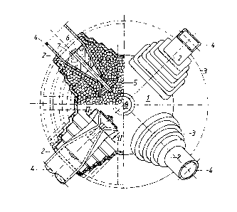
Figure 1 is a perspective view of the joint connection,
ln partial cross section along the axls of one of the rods,
connected to form a joint;
Figures 2, 3 and 4 show cross sections through various
embodiments of a detail of the ~oint connection along the line II-
II in Figure l; and
Figure 5 is a cross-sectional view of a mandrel or plug
shown extending into a filling aperture of the metal casing.
A connection comprises a metal casing 1 with a convex
central portion that is approximately spherical with flattened
1~54~
21~50-17
areas. Projections 3 project in the manner of a star from the
central portion, and these taper down by steps to the openings 2
in the metal casing 1.
In the right hand --unsectioned-- half of Figure 1 there
is an opening 2 for a rod 4, this being in the form of a
rectangular tube, and another opening 2 for a rod 4 in the form of
a round tube. An advantage of the joint connection according to
the present invention is seen in that fact that the rods 4 do not
all have to be of the same cross section. As an example, diagonal
rods can be lighter than boom or chord rods.
The left-hand half of Figure 1 shows two rods 4 that are
combined to form a joint; the axes of these two rods lie in the
plane of the drawing. The upper portion of the left-hand half of
Flgure 1 also shows the filling material in the metal casing 1.
This filling i8 not shown in the lower section of the left-hand
half of Figure 1, and the end section of the rod 4 arranged there
is not shown in crosg section.
It can be seen that the rods 4 within the metal casing
terminate in an end section that forms a shape-locking fit, this
being necked down. It can be seen from the cross section of the
necked down end sections of the rods 4 in Figures 2. to 4 that the
necked down section is formed by crimping the tube walls, this
being done without any concomitant weakening or change in their
cross section area.
,,. ~
~9~
21950-17
In each necked down end section of the rods 4 there are
two opposing expander elements 5, 6 on opposite sides of the
necked down section. The necked down section is matched to the
shape of the expander elements 5, 6. The two expander elements 5,
6 can be tightened down towards each other longitudinally within
the end section of the rod 4 by means of a tensioner 7 located in
the axis of the tube, thls being in the form of a high tensile
strength bolt or a plurality of such bolts (Figure 4), so that
they lie closely against the inner walls of the tube on opposite
sides of the necked down portion.
A filler opening 8 i8 provided on the top surface of the
metal casing 1.
The filling within the metal casing 1 conslsts of a
pressure resistant granulated solid and a hardening fluld that
fills the ~paces between the gralns of the granulate. The
granulated solld is advantageously a single-grain materlal that ls
selected in the range between 6 and 100, preferably between 10 and
50 mm so that the grain slze together with the hardening fluid
,~J ensures an homogeneous fllling for the metal casing 1.
With reference to Figure 5, the filler opening 8 that is
provided at the top of the metal casing 1 is several times greater
than the grain size of the granulated solid. This opening can be
closed by means of a pointed mandrel 9 that pro~ects into the
metal casing 1. The mandrel can, for example, be provided with an
12~5~64
21950-17
external thread 10 for engagement with a suitable matching
internal thread in the filler opening 8. The mandrel 9 is shown
having an aperture 11 through which the hardening fluid can be
inserted.
According to the present invention, the joint is
produced as follows.
First, the pressure resistant granulated solid is
introduced into the metal casing 1 into which the end sections of
the rods 4 protrude. This granulated solid is then consolidated
by applying a vibrator to the metal casing 1. After this, the
mandrel 9 with its pointed end 12 that projects into the metal
casing 1 i8 screwed into the filler opening 8, so that the
granulated solid is pre-loaded. Finally, the non-contracting or
low-contractlon hardening fluid is lntroduced into the metal
caslng 1. An alr bleed and level-control opening -- not shown in
the drawings -- is provided at the highest point of the metal
casing 1.