Note: Descriptions are shown in the official language in which they were submitted.
1~55~4
CAI.IBRATION OF FLUID DELIVI~Y EQUIPMENT
This invention relates to the calibration of fluid
delivery equipment, and is particularly, although not
exclusively, concerned with the calibration of
equipment for delivering herbicides.
Different herbicide formulations have different
properties, and in particular their viscosities may be
different. Thus, where herbicide is fed through a
restrictor to a distribution element for distribution
over the ground, the flow rates through the restrictor
will not be the same for two different formulations.
Furthermore, the flow rate of herbicide will vary from
one piece of equipment to another, even when they are
set to give the same nominal flow rate.
Modern herbicides are highly effective, and very
small quantities are required by comparison with the
highly diluted formulations which have been used in the
past. Consequently, for maximum effectiveness and
efficiency, there must be very accurate control of the
rate of delivery of the herbicide from the delivery
equipment. It is not, in most cases, adequate merely
to rely on a rough-and-ready setting of the equipment.
Hitherto, equipment has been calibrated to establish
accurate flow rates by operating the equipment so that
the fluid is delivered into a measuring jar. The
equipment is operated for a predetermined time, for
example one minute, and the volume of fluid delivered
into the measuring jar is then measured, and a
calculation is performed to determine the actual flow
rate of herbicide. The equipment is then ad~usted, and
the operation repeated, until a desired flow rate is
achieved.
The problem with this procedure is that the
substantial quantities of herbicide which are delivered
into the measuring jar need to be disposed of. Modern
herbicides are expensive, and consequently it is
l~S5f34
--2--
wasteful merely to throw it away. Moreover, the
herbicide must be disposed of with care if unwanted
damage to plants, and dangers to humans and animals, are
to be avoided. Safe disposal can be a particular
problem to an operator who is working at some distance
away from an appropriate waste disposal facility.
These problems are particularly acute where the
herbicide for distribution is contained in a package
which has a small outlet aperture for connection to the
equipment, but which has no provision for refilling.
An aspect of this invention is as follows:
A calibration device for use with fluid delivery
equipment comprising an outlet through which, in normal
use of the equipment, fluid is discharged into the
ambient surroundings, the device comprising a vessel
which is provided with connection means for releasably
connecting the vessel in a fluid-tight manner to the
delivery equipment with the outlet in communication with
the interior of the vessel, the device further
comprising pressure equalizing means for equalizing the
pressure inside and outside the vessel as fluid flows
into the vessel through the outlet, and as fluid returns
to the equipment from the vessel through the outlet.
By using a calibration device in accordance with
the present invention, the herbicide which has been
discharged into the vessel during a measuring operation
can simply be returned through the equipment to its
original container, for example by inverting the
equipment to allow the material to pass back through the
outlet under gravity. Furthermore, by providing means
for connecting the vessel to the delivery equipment, the
risk of accidental spillage of the material is avoided.
In a preferred embodiment, the connecting means
comprises an intermediate component which may be a snap
fit on the delivery equipment. The intermediate
5S84
component is preferably releasably connected to the
vessel itself.
The pressure equalizing means may comprise venting
means, for example, in the form of a duct which
communicates at one end with the vessel at a position
adjacent the connecting means, and at the other end with
the ambient surroundings at a position away from the
connection means. The duct may comprise a tube which
extends outside the vessel, but preferably it comprises
a duct within the vessel. The duct may comprise a
flexible tube which extends from a port in an end wall
of the vessel to a position near the connecting means.
The end of the tube near the connecting means may be
provided with a hood to prevent fluid entering the
vessel from flowing into the tube. The hood may be
provided with spacer means to prevent the tube ends from
contacting the vessel wall.
Other aspects of this invention are as follows:
A method of calibrating fluid delivery equipment
comprising an outlet through which in normal use of the
equipment, fluid is discharged to the ambient
surroundings, the method comprising the steps of:
(a) releasably connecting a calibration vessel to
the delivery equipment in a fluid-tight
manner, with the outlet of the equipment
opening into the vessel;
tb) adjusting the delivery equipment to provide a
desired flow rate;
(c~ operating the delivery equipment for a
predetermined time to discharge fluid into the
vessel;
(d) measuring the volume of fluid in the vessel;
(e) comparing the volume of fluid in the vessel
with the desired flow rate;
(f) returning the fluid to the equipment from the
vessel through the outlet.
55f34
-3a-
A method of calibrating fluid delivery equipment
comprising an outlet through which in normal use of the
equipment, fluid is discharged to the ambient
surroundings, the method comprising:
(a) releasably connecting a calibration vessel to
the delivery equipment in a fluid type manner,
with the outlet of the equipment in fluid
communication with the vessel;
(b) operating the equipment at a desired flow rate
for a predetermined time;
(c) correlating the volume of fluid in the vessel
with the desired flow rate, and
(d) returning the fluid in the vessel to the
equipment through the outlet.
For a better understanding of the present
invention, and to show how it may be carried into
effect, reference will now be made, by way of example,
to the accompanying drawings, in which:
Figure 1 shows delivery equipment for herbicide;
Figure 2 is an exploded, partially sectioned, view
of part of the delivery equipment of Figure 1 and of a
calibration device;
Figure 3 is a view on the line III-III of a
component of the calibration device;
Figure 4 is a view on the line IV-IV of another
,~
129~5t~4
--4--
component of the calibration device;
Figure 5 is a view corresponding to Figure 2, but
showing the components assembled;
Figure 6 is a partially sectioned exploded view of
an alternative embodiment of a calibration device;
Figure 7 is a partially sectioned view of a third
embodiment of a component of the calibration device;
Figure 8 is a sectional side view of another
alternative embodiment of a calibration device;
Figure 9 is a sectional view on the line IX-IX in
Figure 8;
Figure 10 is a sectional view on the line X-X in
Figure 8; and
Figure 11 is a sectional view on the line XI-XI in
Figure 10.
The equipment shown in Figure 1 comprises a hand-
held herbicide delivery device, or "lance", which is
intended to be carried by an operator who walks over
p the ground to be treated. The lance comprises a
handset 2 which i5 provided with an on-off valve and
other appropriate operating controls 4. A rigid
support member in the form of a tube 6 extends from the
handset 2 and carries a delivery head 8. The head 8
accommodates an electric motor (not shown) for driving
a distribution element 10 in the form of a spinning
disc. The head 8 also accommodates a metering valve
mechanism for controlling the rate of flow of herbicide
to the disc 10.
A tube 12 extends from the handset 2 for
connection to a container of herbicide.
In use of the equipment shown in Figure 1,
herbicide flows through the tube 12, the handset 2 and
the tube 6 to the head 8. From the head 8, the
herbicide flows at a metered rate through an annular
outlet aperture 58 (Figure 2) to the spinning disc 10
which discharges the herbicide by centrifugal force to
lX9S5~'~
--5--
form droplets which fall onto the ground to be treated.
A suitable head 8 is disclosed in British Patent
Specification No. 2172524, to which reference is
directed. The valve mechanism in the head 8 is
adjusted, to vary the flow rate of herbicide to the
spinning disc 10, by rotating the outer housing of the
head 8 relatively to the rest of the equipment. This
adjustment varies the cross-section of a flow passage
through the head 8.
In order to calibrate the equipment, it is
necessary to know the actual flow rate of a specified
herbicide through the head 8 for any particular setting
of the valve mechanism. For the same position of the
valve mechanism, the flow rate of a relatively viscous
herbicide formulation will be lower than that for a
less viscous formulation, and so the setting of the
valve mechanism alone cannot provide an accurate
indication of flow rate under all conditions and with
all formulations.
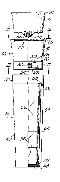
Calibration of the equipment is achieved using the
calibration device shown in Figure 2 to 5. This device
comprises a vessel 14 and an intermediate component 16.
The intermediate component 16 comprises a sleeve
18 which is tapered to conform to the outer periphery
of the head 8. At the wider end of the sleeve 18,
there is an internal circumferential rib 20 which
extends most of the way around the intermediate
component 16. There is a discontinuity in the rib 20
because the sleeve 18 has an arcuate recess 22 in order
to accommodate a projecting tab 24 of the head 8. This
tab 24 forms part of an indicating device for
indicating the relative rotary position of the head 8
with respect to the rest of the equipment.
At the narrow end of the sleeve 18, there is a
cylindrical skirt 26. Four radial webs 28 and a
partition 29 extend inwardly from the skirt 26 to
S5~
support an annular collar 30. Further webs 32 extend
inwardly from the collar 30 and support a central boss
34 which has a bore 36 for receiving a spindle 38 of
the motor within the head 8.
The vessel 14 has a main body 4Q which is tapered
from top to bottom as shown in Figures 2 and S. At its
top end, the vessel 14 has a cylindrical portion 42 in
which the skirt 26 is a friction fit. A longitudinal
recess 44 extends substantially the full length of the
body 40 and terminates at the top end in a transverse
partition 46. The base of the body 40 is recessed and
accommodates a plate 48. The partition 46 and the
plate 48 each have an aperture 50, 52 which are aligned
with each other and receive opposite ends of a tube 54.
The tube 54 thus communicates with the interior of the
vessel 14 ad;acent its top end, i.e. adjacent the
intermediate component 16. At its lower end, the tube
54 communicates with the ambient surroundings.
The vessel 14 is provided with graduations 56
which, for example, represent the volume of liquid
within the vessel.
In order to calibrate the equipment of Figure 1,
the intermediate component 16 and the vessel 14 are
fitted together by locating the skirt 26 within the
cylindrical portion 42. The disc 10 (Figure 1) is
removed, and the intermediate component 16 is clipped
to the head 8 where it is retained by means of the rib
20. The assembled configuration is shown in Figure 5,
and it will be appreciated that the annular outlet
aperture 58 of the head 8 opens into the space between
the collar 30 and the boss 34, and thence to the
interior of the vessel 14. The valve mechanism of the
head 8 is then adjusted to a position which, in the
operator's opinion, will give approximately the desired
flow rate, and the equipment is then operated for a
predetermined time, such as one minute, so that
1;~95~4
herbicide flows directly from the equipment into the
vessel 14.
While fluid is flowing through the aperture 58
into the vessel 14, air is displaced from the vessel 14
through the tube 54. This air enters the tube 54 at
the upper end, retained within the partition 46, and
issues from the lower end of the tube 54 at the end
received in the plate 48. Thus, there is no
possibility that any pressure build up in the vessel 14
will prevent the free flow of herbicide through the
aperture 58.
At the end of the predetermined time, the
equipment is stopped, so shutting off the flow of fluid
through the aperture 58 into the vessel 14. The volume
of fluid which has passed during the predetermined time
is then determined by means of the graduations 56, and
the actual flow rate of fluid through the aperture 58
is calculated. This value is compared with the desired
flow rate, and, if the two are not the same, the valve
mechanism in the head 8 is adjusted in order to
decrease or increase the actual flow rate, as
appropriate. Measurement of the flow into the vessel
14 may then be repeated and the valve mechanism re-
ad~usted as necessary until the actual flow rate
through the aperture 58 is sufficiently close to the
desired flow rate.
In order to avoid wastage of the herbicide
accumulated in the vessel 14, and in order to avoid
difficulties in disposing of this herbicide in a safe
manner, the herbicide can be returned through the
aperture 58 to the container attached to the tube 12
merely by inverting the equipment so that the vessel 14
is raised above the level of the container, and opening
the on-off valve in the handset 2. The herbicide will
then flow under gravity towards the container~ While
this is happening, the herbicide leaving the vessel 14
558~
is replaced by air which passes through the tube 54 to
bubble into the vessel 14 through any herbicide present
at the end adjacent the intermediate component 16.
Thus, the herbicide delivered during the calibration
operation can be returned to the container for
subsequent use without any need for the operator to
handle the herbicide or to remove the calibration
device from the head 8.
Figure 6 illustrates an alternative embodiment.
In this alternative embodiment, the intermediate
component 16 is identical to that described with
reference to Figures 2 to 5, except that there is an
opening 60 in the skirt 26.
The vessel 14 is similar to that of the embodiment
of Figures 2 to 5, but it does not have the tube 54.
Instead, it has an opening 62 in the cylindrical
portion 42 and an opening 64 in the lower wall 66.
This lower wall 66 has a downwardly projecting central
boss 68, on which a metal plate 70 is rotatably
mounted. The plate 70 has an opening 72. In use of
the embodiment shown in Figure 6, when the intermediate
component 16 and the vessel 14 are fitted together with
the skirt 26 frictionally engaged within the
cylindrical portion 42, the openings 60 and 62 can be
moved into and out of alignment with each other by
relative rotation of the vessel 14 relative to the
intermediate component 16. Similarly, the openings 64
and 72 can be moved into an out of alignment with each
other by rotation of the plate 70.
Thus, while herbicide from the head 8 is being
discharged into the vessel 14, the plate 70 will be
rotated into a position in which the opening 64 is
closed, while the vessel 14 will be rotated relatively
to the intermediate component 16 into a position in
which the openings 60 and 62 are in alignment. In this
configuration, air displaced by the incoming herbicide
1'~9S584
g
can be vented from the vessel 14 through the aligned
holes 60 and 62.
When flow of herbicide into the vessel 14 is
terminated, the vessel 14 is rotated relatively to the
intermediate component 16 to move the openings 60 and
62 out of alignment with each other, so closing the
opening 60. The equipment is then inverted to raise
the vessel 14 above the level of the container, and the
plate 70 is rotated in order to bring the openings 64
and 72 into alignment. Air can thus enter the vessel
14 to allow the herbicide to flow back through the
opening 58 (Figure 2), to the herbicide container.
In an alternative modification based on the
embodiment of Figure 6, the plate 72 may be linked to
the intermediate component 16 in such a manner that
rotation of the vessel 14 simultaneously alters the
relative positions of the opening 60 and 62 and the
relative positions of the openings 64 and 72. Thus,
these openings can be controlled merely by rotating the
vessel 14 relatively to the intermediate component 16.
In the embodiment shown in Figure 7, the vessel 14
differs from that shown in Figures 2 and 5 in that the
tube 54' is disposed inside the vessel 14, rather than
in the external cavity 44 of Figures 2 and 5. At its
lower end, the tube 54' is received in an opening 74 in
the lower wall 76 of the vessel 14. At its upper end,
the tube 54' is retained by means of a clip 78 which is
attached to the wall of the vessel 14 at the junction
between the body 40 and the cylindrical portion 42.
Operation of the embodiment shown in Figure 7 is
similar to that of the embodiment shown in Figures 2 to
5.
As with the preceding embodiments, the embodiment
shown in Figures 8 to 11 comprises an intermediate
component 16 and a vessel 14. The intermediate
component 16 has a tapering side wall 18 which receives
584
- 1 0 -
the head 8 at its lower end, and has a nozzle 80 within
which is supported, by struts 82, a central boss 84
having a bore 86 for receiving the motor spindle 38
(Figure 2). The nozzle 80 extends from an end wall 88
5 having a projecting rim 90.
The vessel 14 has a large diameter region 92 and a
smaller diameter region 94, which are connected
together by a conical transition region 96. The
smaller diameter region 94 is connected to a spigot
10 portion 98 by a further conical transition region 100.
Radially extending webs 102, reinforced by a disc 104
at the transition region 100, extend along the smaller
diameter region 94 from the transition region 96. At
their ends away from the larger diameter region 92,
15 these webs have formations 106 which are engagable with
the rim 90 to retain the vessel 14 on the intermediate
component 16.
At the end of the vessel 14 away from the
intermediate component 16, the larger diameter portion
20 92 is closed by a cap 110. A tubular spigot 112
extends inwardly from the cap 110, this spigot opening
into a tubular projection 114 on the outside of the cap
110.
A flexible tube 116 extends from the spigot 112
25 towards the intermediate component 16. The tube 116
terminates within the transition region 190, where it
is provided with a hood 118. The hood 118 is shown in
greater detail in Figures 10 and 11. It comprises a
conical body 120 from which extend four radial limbs
30 122. From the centre of the body 120 projects a
cruciform pro;ection 124, each limb of which has a step
126 near the body 120.
The tube 116 is fitted over the cruciform
projection 124, abutting against the steps 126, which
35 serve to space the end of the tube 116 from the body
120., Thus, the hood 118 cooperates with the tube 116
SSfi4
to provide passages 128 bet~een the limbs of the
cruciform projection 124, enabling air to pass into and
out of the tube 116 as indicated by the double-headed
arrows 130.
For use, as with the preceding embodiments, the
intermediate components 16 and the vessel 14 are
connected together by means of the rib 90 and the
formations 106, and the intermediate component 16 is
fitted to the head 8. The metering valve on the head 8
is set to a position which is expected to provide a
desired flow rate, and the on-off valve at the handset
is opened to permit fluid to flow through the head 8
and past the struts 82 into the vessel 14. As the
fluid enters the vessel 14, it flows over the hood 118
without passing into the tube 116, and collects at the
bottom of the vessel, in the position shown in Figure
8. Air displaced by the inflowing fluid is able to
flow out of the vessel 14 through the passages 128, as
indicated by the arrows 130. Consequently, no back-
pressure is applied to the fluid flowing into thevessel 14 from the head 8.
The flow of fluid into the vessel 14 is timed for
a predetermined period such as one minute, or thirty
seconds, after which the valve at the handset 2 is
closed. In some embodiments of lance, the liquid may
be pumped to the head, in which case the pump may be
operated for the predetermined time. The lance is then
manipulated to invert the vessel 14, and the level of
the liquid is read off on a scale on the side of the
vessel 14 (which may be transparent for this purpose).
The scale indicates an increasing volume in the
direction away from the intermediate component 16.
Consequently, the scale is expanded in the smaller
diameter region 94 relatively to the larger diameter
region 92, in order to provide greater reading accuracy
when only a small volume of fluid is present in the
~ 5 ~8
vessel 14.
When the reading has been completed, the on-off
valve at the handset 2 is opened, and the fluid then
drains back through the head 8 to the container from
which it was originally supplied. During this
operation, the natural curvature of the flexible tube
116 causes the hood 118 to be tilted, which minimises
the possibility of any fluid collecting in the hood
118. Furthermore, the limbs 122 space the main body
120 of the hood 118 from the sides of the vessel 14
which further minimise the possibility of fluid being
drawn into the tube 116 from the sides of the vessel 14
by capillary action.
When all of the fluid has been returned to its
container, the calibration test may be repeated, after
any necessary adjustment has been made to the metering
valve in the head 8. Alternatively, if the calibration
test indicates that the flow rate at the originally set
position of the metering valve is of the required
magnitude, the intermediate component 16 and the
vessel 14 may be removed from the head so that the disc
may be re-fitted and distribution of the material
begun. The intermediate component 16 and the vessel 14
are provided with clips 132, which can be used to fit
the assembly to the tube 6 (Figure 1).
It will be appreciated that, althouqh the present
invention has been described with reference to a
spraying head 8 which incorporates a valve mechanism,
the invention is also applicable to other forms of
delivery equipment. For example, the principles
underlying the present invention can be applied to
equipment in which adjustment of flowrate can be
achieved by selecting an appropriately sized jet.
Also, the broad principle of the present invention
can be applied to equipment which cannot easily be
inverted to return the fluid from the vessel to the
S5~4
-13-
equipment. Such equipment may, for example, be wheeled
equipment having more than one spraying head. In such
circumstances, the fluid delivered during a measuring
operation may be returned to the equipment by suction.
This may be achieved, for example, by reversing a pump
which is normally used to deliver the fluid to the
spraying head. In order to ensure that substantially
all of the fluid is withdrawn from the vessel, a dip
tube may be connected to the outlet of the equipment,
this dip tube extending to the bottom of the vessel.
In the embodiments described, the pressure inside
and outside the vessel is equalized by venting means,
for example in the form of the tube 54, which permits
the flow of air into and out of the vessel. In an
alternative embodiment, the pressure may be equalized
by providing the vessel with a movable wall, which is
displaced to compensate for the flow of fluid into and
out of the vessel. For example, the movable wall may
be provided by forming the vessel from a flexible
material. The vessel then fills out as the fluid flows
into it and collapses as the fluid flows out.