Note: Descriptions are shown in the official language in which they were submitted.
s
~ FRAM~ IN A PAPER MAKING MACHINE
1 The present invention relates to a frame of a
press-Aehydra~ing section in a paper making machine.
sRIEF DESCRIPTION OF THE DRAWINGS:
In the accompanying drawings:
Fig. 1 is a plan view of a frame structure of one
part of a press-dehydrating section in a papex making machine
according to the present invention;
Fig. 2 is a side view of the same frame structure;
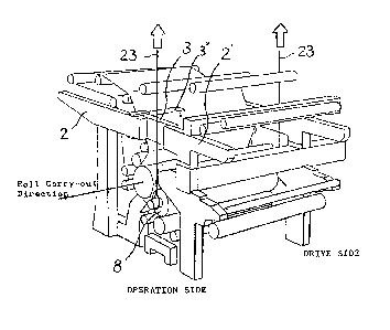
Fig. 3 is a perspective view of the same frame
structure;
Fig. 4 is a schematic view showing a hung state
and a carry-out state of a roll in the same frame structure;
~ig9~ 5(a), S(b), S~c) and 5(d) are schematic
views showing a hung state and a carry-out state of a roll
~ 15 in a frame structure of a paper making machine in the prior
;~ art; ~ `
Fig. 6 is a plan view of a frame structure o~
a paper making machine in the prior art;
Fig. 7 is a side view of a frame structure of
a paper making machine in the prior art;
Figs. 8(a), 8(b), 8(c) and 8~d) are perspective
; views illustrating successive states of taking out a roll
in a paper making machine in the prior art; and
Pig. 9 is a side view showing another system of
~ replacing a roll proposed in the prior art.
:
'
: ~, ' .
-
i5
At first,a ~eneral construction of a press r
dehydrating section in a paper making machine in the prior
art will be described with reference to Figs. 6 and 7.
As shown in these figures, in the press-dehydrating section,
a wet paper web (fiber mat~ l, which has been dehydrated
up to a concentration of about 15 - 18% in the preceding
wet end section and is being carried in, is received, then
it is further dehydrated by making it successively pass
through gaps between a plurality of pairs of press rolls,
and it is carried out to the subse~uent heat-dry section.
The fiber mat 1 is carried from the preceding section with
the aid of a wire 24, that is, an endless net belt which
is wound around a plurality of rolls and is made to run in
the direction of an arrow by a roll 25 rotated by a driving
device not shown, and further it is carried into the press-
dehydrating section by sucking rotation of a s:uction roll
provided at an inlet section of the apparatus. The fiber
mat 1 thus carried in is dehydrated by pinching rotation
~ 20
:~:: ~ :
~; '
:
- 2 -
~L
, .
~,~,. . .. . .
. . . ': '- ' .
.' '- , . ~ ~ ~ :
, . .
,.
'
.
~f~P~S~
of a press roll 28 and a suction roll 29 in a firs-t press
section 27, and it is wound around the suction roll 29 to
be carried to the next press section. Subse~uently, pre-
determined dehydration is effected as passing through a
second press section 30, a third press section 31 and a
fourth press section 32 having a similar capability, and
then the fiber mat 1 is carried out towards the heat-dry
section.
In the above-described first to fourth press
lG sections, one of the paired press rolls has its opposite
axial ends pivotably supported by a bracket 33, and this
bracket 33 is Pixedly secured to a swing arm 34 that i.8
supported rotatably about a shaft 3S and adapted to be
rocked via a cylinder 18. Accordingly, if the above-
mentioned cylinder 18 is actuated via an electromagneticvalve not shown, then a pressing force can be generated
between the paired rolled, but if the cylinder 18 is
; actuated in the opposite direction, a gap space can be
formed between the respective rolls. In addition, if the
pressure applied to the cylinder 18 is made variable, then
the pressing force acted between the rolls can be arbi-
trarily contr~lled, so that at the respective press sections
~ the dehydrating rates can be controlled in a delicate
: manner. It is to be noted that in Fig. 7, reference nu-
: 25 meral 15 aesignates endles~ felts, which are wound around
3 -
,.,~
~..:... .
9~s
a plurality of rolls and are made to run in synchronism
with the running speed of the fiber mat 1 as driven by a
driving device not shown, and which have the functlons of
assisting the desired dehydrating effect and serving as
a guide for conveyance.
As described above, in the press-dehydrating
section, dehydration from the fiber mat 1 is effected by
a strong pressing force between press rolls, and so, it is
necessary to cause a considerably strong roll pressure to
be generated between the paired rolls. Accordingly, the
shaft 35 serving as a fulcrum for the above-described
swing arm 34 is necessitated to have a mechanical strength
enough to well withstand the reaction against the above-
mentioned pressing force, and the frame forming a framework
of the apparatus is also required to have a corresponding
meahanical strength. To that end, it is a common practice
~ that at the opposite side edge portions of the top of the
: apparatus are fixedly extended frames (top beams) 2 along
the direction of traveling of the fiber mat 1 so that the
apparatus may have a mechanical strength enough to well
withstand the above-mentioned reaction.
Now description will be made on the procedure of
replacing a press I'Oll. Among the press rolls, there are
many varieties of :olls corresponding to desired functions
~such as rubber rolls 16 and 17 having their surfaces coated
:
~ ~4 -
'
'
. . . ~ . . .
~ ~9~
with rubber, a suction roll having a hollow inner space and
a plurality of air-permeable holes in its circumferential
wall, a press roll 8 made of different material, or the
like, and hence, during a long period of use, wear and
damage would arise, which necessitate predetermined repairs.
Especially, in the case of a rubber roll, in view of its
structural characteristic, regrinding of its surface would
become necessary due to wear and the like, and normally it
is a common practicé to replace and remedy it at an
interval of three to six months or more.
And replacement of such a roll is carried out
thro~gh the steps of displacing a roll positioned riqht
above the roll to be replaced, forth or back in the travel-
ing direction of the fiber mat 1 up to a predetermined
position, disconnecting a shaft coupling of the roll to be
replaced and a press member for a bearing housing 20 ~See
Fig. S) pivotably supporting the same roll, hanging the
roll right above by means of a hoist equipped on a ceiling,
further transferring it in the axia~ direction towards the
operation side [throughout this specification, the term
"operation side" is used to mean the side faced to a pass-
age of a worker along the travellng direction of the fiber
mat tsometimes it is also called "front side"), and term
~ "drive side" is used to mean the side opposite to the
;~ 25 above-mentioned "operatlon side" (sometimes it is also
~ : - 5 _
,,
~ ~9~ 6~;
called "rear side")], and thereby carrying out the roll up
to a predetermined position.
The process of hanging up and carrying out a roll
in the prior art is lllustrated in Figs~ 5(a) to 5~d), in
which a hoist of 2-crab 3-hook type was used. This type
of hoist operates by making use of two sets of hanging
units consisting of a hanging unit 37 provided with a single
hook 21 and a hanging unit 38 provided with two hooks 36
and 22. At first, ~ires 23 wound around the outside end
portions of a roll shaft are hung by the hooks 21 and 22
at the opposite outer ends and are moved in the axial direc-
tion of the roll under the raised condition as shown in
Figs. 5~a) and 8(a), and they are stopped at the position
shown in Fig. 8(b). Subsequently, a nylon sling 39 wound
around the outer circumference of the roll is hung by the
hook 36 as shown in F'igs. 5(b) and 8(c), then the hook 22
positioned at the end of the roll on the slde of the
machine is lowered, and the wire 23 which was hung by the
hook 22 is disengaged from the latter as shown in Fig. 5(c).
Through the above-mentioned operations, the top
frame 2 above the roll can be avoided, further the roll is
moved in the axial direction to be carried out up to the
position shown in Figs. 5(c) and 8(d), and subsequently,
the roll is conveyed to a predetermined pos~ition. Fig. 5(d)
illustrates the mode of transfer from engagement with a
.
' ''~
'
'. '
wire 23 shown at (A) to engagement with a nylon sling 39
shown at (B). It will be obvious that upon carry-in and
assembling of a roll, operations in the reverse se~uence
to those described above would be effected. As described
above, the replacement of the roll in the prior art neces-
sitated difficult works, which were dangerous and time-
consuming such as rehanging a roll in the midway of
carrying out the roll, in view of interference with a frame
structure.
In addition, as an improved frame structure for
allowing another method of effecting replacement oE a roll
in a simple and safe manner by obviating the rehanging
work, a frame structure that is advantageous for replace-
ment of a roll as disclosed in U.S. Patent Specification
No. 4,608,128, was proposed (See Fig. 9). However, accord-
ing to this method, intermediate frame members ~connection
blocks) 65 are necessitated on both the operation side and
the drive side, and moreover, for the purpose of replace-
ment of a roll, the connection blocks on the both side
must be manipulated to be moved. Also, despite of the fact
that for the purpose of replacement of a roll it is only
~necessary to insure a space for allowing a rope to pass
~: therethrough at least only on the operation side, unneces-
sary works, that:is, the~works of dismounting the block on
, ~ :
~ ~ 25 the drive side and mounting the same are necessitated, and
:::::: :
: . 7
'
~2~
so the procedure for replacement is increased by one step.
Moreover, besides the pressing device for a roll, means 64
for revolving a roll is necessitated on each of the opera-
tion side and the drive side, and so, increase of a cost
of a machine caused by increase of operation steps and
increase of a number of machine parts is brought about.
In the work upon replacement of a roll in the
above-described frame structure of a press~dehydrating
apparatus in a paper making machine in the prior art, since
movement of wires 23 necessitated for hanging and carry-out
of a roll is lim:Lted by a frame ~top beam) 2 fixedly
extended along the direction of traveling of a fiber ma~
at the opposite side edge portions of the top of the above-
described press-dehydrating apparatus, inevitably the
operation of rehanging a roll with the aid of an additional
; hook 36 in the midway of carrying out the roll was effected,
as a counter-measure for avoiding the same frame 2. More-
over, there were problems such tha-t the above-described
operation of rehanging a roll which is a heavy-weight body
was a very dangerous work, and that due to this rehanging
work, a loss time necessitated for replacement of a roll
; was also large.
SUMMARY OF THE INVFNTION:
It is therefore one object of the present inven-
tion to provide a novel frame of a press-dehydrating
- 8 -
;~ .
,. ,~ " .. .
~29~ iS
apparatus in a paper making machine in which the above-
described problems in the prior art are resolved.
According to one feature of the present invention,
there is provided an improved frame of a press-dehydrating
,apparatus in a paper making machine, in which a desired
length portion of the frame positioned above a roll which
is necessitated to be replaced such as a press roll or the
like is cut out, and both portions of said frame facing
said cut-out portion are coupled by another frame member
that is swingable by a predetermined angle in a horizontal
plane.
According to the present invention, upon replace-
ment of a roll, since a free space can be formed above the
roll to be replaced by making the another frame member
15 which is made`swinyable by a predetermined angle, revolve,
it becomes unnecessary to avoid interference between a
hanging wire and the frame, and so, the roll hung by the
wire can be carried out to the outside of the apparatus
under the initially hung condition.
The above-mentioned and other objects, features
and advantages of the present invention will become more
~ apparent by reference to the following description of one
;~ preferred embodiment of the invention taken in conjunction
with the accompanying drawings.
25~ DESCRIPTION OF THE PREFERRED EMBODIMENT: ~
Now the present~invention will be described in
g
s
greater detail in connection to one preferred embodiment of
the invention illustra-ted in Figs. 1, 2, 3 and 4. It is to
be noted that since the general construction and function
of the press-dehydrating apparatus are :identical to those
of the press-dehydra-ting apparatus in the prior art shown
in Fig. 7, similar component parts are designated by like
reference numerals.
As shown in Fig. 1, among the frame (top beam) 2
extended in the direction oE traveling of a fiber mat 1
along the side edges of the top of the press-dehydrating
apparatus, a desired length portion of the Erame 2 pos:i-
tloned on the operatlon s:ide above a press roll or the l:Llce
is cut out, and the Erame portions 2 and 2' facing the
cut-out portion is coupled via a separate swing frame 3
lS that can swing by a predetermined angle in a horizontal
plane. More particularly, one end of the swing frame 3 is
pivotably supported from a bracket 5 projected from the
left side frame portion 2 via a shaft 4 so that the swing
arm 3 can swing about the shaft 4 in a horizontal plane,
and the other end of the swing frame 3 is fixedly secured
by a bolt 6 to the right side frame portion 2'. It is to
be noted that in Fig. 1, reference numeral 7 designates
a posltlonlng metal piece, which func-tions to restrain
;~ the position of the swing frame 3 and to preven~ deviation
of the travellng direction of the Fiber mat 1 in the case
: :
:
,
- 1 0
of connecting and fastening the swing frame 3 to the right
side frame portion 2'. Thereby during operation of the
paper making machine, the left and right frame portions 2
and 2' can be surely held in an integrated state as coupled
via the swing frame 3.
Next, description will be made on the procedure
of replacernent of a roll, by way of example, with respect
to the case of a press roll 8. A-t first, by rotating an
arm lO which pivotably supports a fel-t roll 9 positioned
left-above the press roll 8, the felt roll 9 is moved to
a position 9' depicted by a dash-dot line, then a :Eelt
roll 11 positloned just above the press roll 8 is separated
from an arm 12 and is moved to a posltion 11' likewise
depicted by a dash-dot line and placed on a roll :receiver
13 disposed -there. In addition, the arm 12 having the felt
~ :~ roll 11 dismounted~therefrom is rotated about a pivotal
:~ : shaft 14 and moved upwards to be settled at a position 12
depicted by a dash~dot line.:
Subsequently, two press rolls 16 and 17 held in
contact with the press roll 8 via a Eelt 15 are moved back
and forth, respectively, in the traveling direction of the
fiber mat 1 by inversely actuating cylinders 18 associated
with the respective press rolls, and thereby gap spaces
:; are~formed between~the press roll 8 and the respective
: ~ :
~ 25 press rolls 16 and 17. Regarding releasing operations for
:
:
~2"~ S
the swing frame 3, bolt 6 which fasten the swing frame 3
to -the right side frame 2' is extracted, and then the swing
frame 3 is rotated about the shaft 4 towards the center of
-the machine with the aid of driving means 19 as shown by
dash-dot lines. It is to be noted that in Fig. 2, by way
of example, a torque cylinder is provided as rotational
drive means 19 for the swing arm 3. Next 7 a shaf-t coupling
for the press roll 8 and a press mernber for a bearing 20
which pivotably supports the press roll 8 are disconnected,
then the press roll 8 is hang up right above by means oE
a hoist equipped at the ceiling, Eurther the press roll 8
i8 transferred in the axial direction towards the operation
side, and lt ls carrled out up to a predetermined posltion.
Now, the operation will be described in greater
detail with respect to the case where a;hoist of two-crab~
; ~ two-hook type as ~hown in Fig. 4 is employed. This hoist~
funct1ons by cooperatio~n~of~two sets of~hanglng units~37
each provided with a single hook. As shown~at (A) in
Fig. 4, wires 23 wound around the outer end portions of
the shaEt o;E the press roll 8 are hung by a pair of hooks
21, and while the press rolI 8 is kept raised, it is moved
up t~o the position~shown at (B) ln Fig. 4, that is, in the
ax~ial direction of the roll towards the~operation side.
With the~rame s-tructure according to the present inven-
25~ ticn,~;slnce a predetermined~space~can be formed ln the ~;
, ;,, .
~2~5~r~
passageway of the hanging wires 23 above the press roll 8owing to the rota-tional displacement of the swing frame 3,
the rehanging work in the midway of the carry-out operation
as necessitated in the case of the frame structure in the
prior art, is unnecessary. In addition, in the case of
carrying in and assembling a roll, it is only necessary to
perform inverse operations to those described above. Owing
to the above-described construction and function of the
novel frame structure, great shor-tening of a working time
necessitated for replacement of a roll as well as imp.rove-
ment in afety o~E operations can be real.ized. As to the
rotational dr:Lve means for the swincJ frame 3, besicles the
illustrated torque cylinder, various types of drive systems
such as a hydraulic cylinder or the like can be conceived,
and a method of manually manipulating the swing frame 3~
aould be employed. It is to be noted that a perspective
; ~ view showing a state of taking out a roll is depicted ln:
Fig. 3.
Since the frame in a paper making machine accord-
ing to the present inven-tion has the above-described
: structural and functional features and a part of a frame
:positioned aboye a roll tha-t is neces;sitated to be replaced
can be displaced to a different location by making it swing,
a~space can be formed over a desired length, and hence, in
a 25 the~case of carrying out the roll by hanging it, obstacles
~ 13 -
:: ~ :
;~, :
. ~ ~
5~
in -the passageway of wires hanging that roll are eliminated
owing to appearance of this space. Accordingly, -the work
of reengaging hanging wires around a roll as necessitated
in the prior art becomes unnecessary, and a roll can be
carried out to the outside of the apparatus under the
condition where the roll was initially hung up. Conse-
~uently, the most dangerous rehanging work is obviated,
a working time necessitated for replacement of a roll can
be greatly shortened, and so, improvement in an availa-
bility Eactor, that is, improvement in a produc-tivity can
be achieved.
Whi:Le a pr:i.nciple oE the present invention has
been described above in connection to one preferred
embodiment of the invention, it is intended that all matter
contained in the above description and illustrated in the
accompanylng drawings shall be interpreted to be illustra-
tive and not in a limiting sense.
::
: ~: : : : :
~ 14
., . ~ .