Note: Descriptions are shown in the official language in which they were submitted.
PP~OCESS FOR THE SEPAR~TION OF IIYDROCARBONS
E'ROM A MIXED_FEEDSTOCK
Technical Field
This invention relates to a steam distillation
process for the recovery of hydrocarbons from a mixed
feedstock.
Backyround
The benzene-toluene-C8 aromatic ~raction
(known and hereinafter referred to as BTX) is now well
established as a premier raw material in the manufacture
of petrochemicals and as a desirable component in
boosting octane ratings in gasoline. Many processes
have been proposed in U.S. Patent 3,714,033, which is
incorporated by reference herein.
There is an industrial need ~or BTX, which is
available in high proportion, e.g., greater than 30
percent by weight, in a wide variety of hydrocarbon
feedstocks such as reformed gasolines; coke oven light
oils; and cracked gasolines. These feedstocks also
contain both aliphatic and cycloaliphatic hydrocarbons.
Since the individual hydrocarbon compounds which make up
these ~eedstocks are well known, they will not be
discussed extensively; however, it can be pointed out
that the major components of the feedstocks used herein
are hydrocarbons with boiling points ranging from 25C
- ~ -
to 175C including straight-chain and branched-chain
paraffins and naphthenes, such as n-heptane,
isooctane, and methyl cyclohexane, and aromatics
such as BTX.
The BTX fraction can include benzene,
toluene, the C8 aromatics including ortho-xylene,
meta-xylene, paraxylene, and ethyl benzene, and Cg
aromatics, which, if present at all, appear in the
smallest proportion in relation to the other
components.
The solvents used in solvent
extraction/steam distillation processes for the
recovery of BTX are water-miscible organic liquids
(at process temperatures) having a boiling point of
at least about 200C and having a decomposition
temperature of at least about 225C. The term
"water-miscible" includes those solvents which are
completely miscible over a wide range of
temperatures and those solvents which have a high
partial miscibility at room temperature since the
latter are usually completely miscible at process
temperatures. The solvents are also polar and are
generally comprised of carbon, hydrogen, and oxygen
with some exceptions. Examples of solvents which
may be used in the process of this invention are
dipropylene glycol, tripropylene glycol, dibutylene
glycol, tributylene glycol, ethylene glycol,
diethylene glycol, ethylene glycol monomethyl ether,
ethylene glycol monoethyl ether, diethylene glycol
monomethyl ether, diethylene glycol monoethyl ether,
sulfolane, N-methyl pyrrolidone, triethylene glycol,
tetraethylene glycol, ethylene glycol diethyl ether,
.
D-14,627-1
.~
6
-- 3 --
propylene glycol monoethyl ether, pentaethylene
glycol, hexamethylene glycol, and mixtures thereof.
The preferred group of solvents is the polyalkylene
glycols and the preferred solvent is tetraethylene
gly~ol.
Additional solvents, which may be used
alone or together, or with t:he aforementioned
solvents are amides such as formamide, acetamide,
dimethylformamide, diethylformamide, a~d
dimethylacetamide; amines such as diethylenetriamine
and triethylenetetramine; alkanolamines such as
monoethanolamine, diethanolamine, and
triethanolamine; nitriles such as
beta,betal-oxydipropionitrile and
beta,betal-thiodipropionitrile; phenol and the
cresols; the methyl sulfolanes; sulfoxides such as
dimethyl sulfoxide and diethyl sulfoxide; lactones
such as gamma-propiolactone and gamma-butyrolactone.
The apparatus used in the process both for
extraction and distillation is conventional, e.g.,
an extraction column of the multi-stage
reciprocating type containing a plurality of
perforated plates centrally mounted on a vertical
shaft driven by a motor in an oscillatory manner can
be used as well as columns containing pumps with
settling zones, sieve trays with upcomers, or even a
hollow tube while the distillation can be conducted
in a packed, bubble plate, or sie~e tray
ractionating column. Counter-current flows are
utilized in both extraction and distillation columns.
Heat exchangers, decanters, reservoirs,
solvent regenerators, condensers, compressors, and
pumps as well as various extractors other than the
D-14,627-~
main extractor can also be used to complete the
system. The other extractors are preferably single
stage mixer-settlers, but can be any of the well
known types. Again, all of this apparatus is
conventional off-the-shelf equipment commonly used
in extraction/distillation processes.
The solvent is used as an aqueous solution
containing water in an amount of about 1 percent to
about 10 percent by weight based on the weight of
the solvent and preferably containing water in an
amount of about 2 percent to about 6 percent by
weight.
Generally, to accomplish the extraction,
the ratio of solvent (exclusive of water) to
feedstock in the extractor is in the range of about
4 to about 8 parts by weight of solvent to one part
by weight of feedstock. This broad range can be
expanded upon where nonpreferred solvents are used.
A broad range of about 3 to about 12 parts by weight
of solvent to one part by weight of feedstock and a
preferred range of about 5 parts to about 7 parts of
solvent per part of feedstock can be used
successfully for the solvent of preference and other
li~e solvents. In final analysis, however, the
ratio is selected by the technician based on
experience with the particular feedstock and depends
in part upon whether high recovery or high purity is
being emphasized.
The reflux to the extraction zone, an
important part of the process, is generally made up
of about 20 percent to about 50 percent by weight
aliphatics having from 5 to 7 carbon atoms and about
D-14,627--1
~ Z~3 ~S~Ç~.~
50 percent to about 80 percent by weight aromatics,
both based on the total weight of the reflux. The
ratio of reflux to feedstock in the extraction zone
is, generally, maintained in the range of about 0.5
to about 1.5 parts by weight of reflux to one part
by weight of feedstock and preferably about 0.5 to
about 1.0 part by weight of reflux to one part by
weight of feedstock, but, again, is selected by the
technician just as the ratio of solvent to
feedstock. The reflux aliphatics pass into the
extract rather than being taken overhead with the
raffinate and are recycled to the extractor from the
reflux decanter.
The temperature in the extraction zone is
maintained in the range of about 100C to about
200OC and is preferably in the range of about 125C
to about 150C, especially for the solvent of
preference.
The pressure in the extraction zone is
maintained in the range of about 75 psig to about
200 psig. As is well know in the art, however, one
selected pressure is not maintained throughout the
extraction zone, but, rather, a high pressure within
the stated range is present at the bottom of the
zone and a low pressure, again within the stated
range, is present at the top of the zone with an
intermediate pressure in the middle of the zone.
The pressures in the zone depend on the design of
the equipment and the temperature, both of which are
adjusted to maintain the pressure within the stated
range.
D-14,627-1
.
The temperature at the top of the
distillation zone, which, in terms of the apparatus
used, may be referred to as a distillation column or
stripper, is at the boiling point of the mixture of
aromatics present in the zone while the temperature
at the bottom of the stripper is generally in the
range of about 135C to about 200C.
The pressure at the top of the stripper, an
upper flash zone in this case, is in the r~nge of
about 20 psig to about 45 psig. ln a lower flash
zone just beneath the upper flash zone and connected
thereto, the pressure is in the range of about 10
psig to about 25 psig and is about 10 or 20 psig
lower than the pressure in the upper flash zone.
The pressure in the rest of the distillation zone is
maintained in the range of about 15 psig to about 25
psig with some variation throughout the zone.
The steam or steam/water mixture brought
into the bottom of the distillation zone enters at a
temperature of about 100C to about 150C and is
under a pressure of about 15 psig to about 25 psig.
The total water and/or steam injected into the
distillation column is in the range of about 0.1
part to about 0.5 part by weight of water to one
part by weight of aromatics in the æone and
preferably in the range of about 0.1 part to about
0,3 part by weight of water to one part by weight of
aromatics. The water used for the stripping steam
is usually called stripping water. A small amount
of water is present in liquid form in the
distillation zone dissolved in the solvent.
D-14,627-1
&6
- 7 -
Typically, in solvent extraction/steam
distillation processes, the feedstock is preheated
and then introduced to the main extractor at about
the middle tray. An aqueous solvent solution (known
as lean solvent) enters at the top tray of the
extractor and percolates down the column removing
aromatics from the feedstock. The raffinate,
essentially free of aromatics, leaves the top of the
column. Provisions are made for the recovery of
solvent and any remaining aromatics from the
raffinate as well as the water which is used to wash
it. In the lower half of t:he extractor, the solvent
solution of aromatics comes into countercurrent
contact with a reflux li~uid, which enters the
extractor below the bottom tray. The re1ux
percolates up the lower half of the extractor
progressively dissolving in and purifying the
solvent solution of aromatics. The extract ~known
- as rich solvent) leaves the bottom of the extractor
and enters the stripper (or distillation zone) at an
upper flash chamber. Part of the extract flashes on
entering the flash chamber and is taken overhead in
vapor form and the other part of the extract passes
as a liquid into a lower flash chamber. Again, part
of the extract, flashes overhead and the balance of
the extract ~at least about 80 percent by weight)
percolates down the column into the fractionation
zone where it comes into countercurrent contact with
the stripping vapors, i.e., steam, and more vapors
are generated. A part of the vapors rises to the
top of the column where it mixes with flash vapors
to form the overhead distillate. The overhead
D-14,627-1
:
~ &
distillate provides reflux for the extractor. After
the rich solvent descends about halfway down the
column, it becomes essentially free of aliphatics,
At this point, a vapor side-cut distillate is
removed. The side-cut distillate is separated into
its aromatics and solvent/water components, the
aromatics being recovered and the solvent and water
being recycled into the system. Stripping water
from the side-cut distillate and other water from
the system is returned to the bottom o the stripper
as steam or a steam/water mixture. The bulk of the
solvent and water leaves the bottom of the
stripper. A portion of this solution is directed to
a reboil~r where it is vaporized and then returned
to a point below the bottom tray of the stripper to
provide heat therefor. The balance of the
solvent/water solution is recycled to the top tray
of the main extractor.
There are many specific variations of the
above process, each of which seeks either to reduce
apparatus requirements, i.e., capital expenditure,
or energy consumption, or make more effective use of
process components while meeting purity
specifications.
SummarY of the Invention
By this invention steam distillations can
be conducted with reduced energy consumption by the
indirect heat exchange of the overhQad from the
distillation zone with water at a pressure lower
than that in the distillation zone. This lower
pressure is sufficient to enable water to be
vaporized and is maintained by passing the vaporized
D-14,627-1
9 -
overhead to the low pressure port of a fluid ejector
through which a higher pressure stream entering the
distillation zone, such as a feed stream or steam,
is passed. Additional reduction of energy
consumption can be achieved by passing the
unvaporized water from the heat exchanger to a
motive steam generator ~nd using the motive steam as
the fluid for the fluid ejector~
~ Not only can the processes of this
- invention offer reduced energy consumption, but,
also, the processes enable the re-use of stripping
water. In many steam distillation processes, the
stripping water in the overhead from the
distillation zone contains minor portions of the
components to be separated. Thus, the stripping
water may not be suitable for disposal or for use in
other process e~uipment such as steam boilers. The
processes of this invention can enable this
stripping water to be recycled to the steam
distillation zone in an economic and efficient
manner in which heat is recovered from the overhead
stream and effectively returned to the steam
distillation zone. Moreover, the process may be
practiced with little capital in~estment and without
undue maintenance because of the use of the fluid
ejector to maintain the lower pressure in the heat
exchange.
The process may be suitable for ~arious
steam distillation operations wherein a
substantially water-immiscible component is being
separated. These separations include the separation
of hydrocarbons, essential oils, fatty acids,
turpentine, pine oil, camphor, monomers from
D-14,627-1
s~
-- 10 --
polymers and the like, and can find application in
processes such as acid gas removal processes, the
Benfield process, alkanolamine acid gas treating
system, and the like.
According to one aspect of the invention,
an improvement has been found in a steam
distillation process for the recovery of
hydrocarbons wherein there is (i) a primary flash
zone at the top of the distillation zone in which
rich solvent is flashed ancl/or (ii) provision for
the removal of side-cut distillate vapors from about
the middle of the distillat:ion zone.
The improvement comprises (a) heat
exchanging flashed rich solvent vapors or side-cut
distillate vapors with stripping water to provide
stripping water vapors and stripping water at at
least about the boiling poin~c of water; (b) passing
the stripping water vapors from step (a) to a steam
ejector; ~c) passing the stripping water from step
(a) to a motive steam generator wherein the
stripping water is v~porized under pressure; (d~
passing the stripping water vapors from step ~c) to
the steam ejector rPferred to in step (b~; and (e)
passing the stripping water vapors, introduced into
the steam ejector in accordance with steps (b) and
(d~, to the lower half of the distillation ~one.
In another aspect of the invention, an
overhead vapor stream from the distillation zone is
heat exchanged with stripping water at a temperature
which under the pressure of the heat exchanging is
at least about the boiling point of water whereby
stripping water vapors are produced and passed to a
D-14,627-1
steam ejector. Steam, at a higher pressure, is
passed through the steam ejector into the
distillation zone whereby the pressure of the heat
exchange is lower than the pressure of the steam
distillation.
In a further aspec1: of the invention, a
feed stream containing at least one substantially
water-immisci~le component to be separated and an
operative stream containing at least one of water
and steam are introduced into a steam distillation
vessel which is maintained under steam distillation
conditions including temperature and pressure to
provide a vaporous overhead stream containing the at
least one component to be separated and a liquid
bottoms fraction. The liquid bottoms fraction is
withdrawn from a lower portion of the vessel and the
overhead stream is withdrawn from an upper portion
of the vessel and is passed through an indirect heat
exchanger. The overhead stream is condensed to
provide a liquid stream rich in the at least one
component to be separated and a water stream. At
least a portion of the water stream is passed to the
indirect heat exchange as the heat exchange medium
and at least a portion of the water stream in the
indirect heat exchanger is vaporized at a lower
absolute pressure than the pressure in the steam
distillation vessel. This vaporized stream is
passed to a lower pressure inlet of a fluid ejector
through which at least one of the feed stream and at
least a portion of the operative stream is passed at
a higher absolute pressure into the steam
distillation vessel whereby the heat e~change medium
D-14,6~7-l
.
1 2~ 6
side of the indirect heat exchanger is maintained at
said lower absolute pressure sufficient to generate
steam using heat contained in the overhead stream.
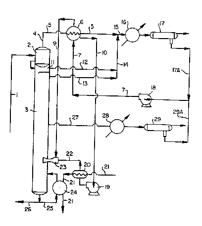
Brief Description of the Drawinq
The sole figure is a schematic flow diagram
of an illustrative embodiment of the subject
invention.
Detailed Description
The main extractor, feedstock, solvent,
temperatures, and pressures are as described above
except as noted. While subject process can be
applied to any steam distillation process, which
provides or a primary flash zone and/or side-cut
distillate vapors, the application of particular
interest is a solvent extraction/steam distillation
process for the recovery of aromatic hydrocarbons.
Referring to the drawing:
The rich solvent from the extractor (not
shown) is at a temperature in the range of about
100C to about 150C. It passes along line 1 to
primary flash chamber 2 at the top of stripper 3.
Primary flash chamber 2 is maintained at a pressure
in the range of about 20 pounds per square inch
gauge (psig) to about 60 psig. Part of the
hydrocarbon and water in the rich solvent is flashed
overhead along line 4 to pass as a vapor through
line 5 at a temperature in the range of about 90 to
about 140C and at a pressure in the range of about
15 psig to about 55 psig entering, prior to its
condensation, into stripping water vaporizer (heat
D-14,627-1
,5~3~i6
- 13 ~
exchangersj 6. The stripping water enters vaporizer
6 along line 7 at a temperature in the range of
about 35 to about 80C. As the primary flash vapors
condense, the stripping water is heated to about
100C, the boiling point of water at atmospheric
pressure. Part of the stripping water is vaporized
at about one atmosphere. I'he other part remains as
a liquid. In the event that vaporizer 6 is operated
at less than atmospheric pressure, the boiling point
of water will, of course, be reduced accordingly.
The ætripping water is split into two
streams, the vapor following line 9 and the liquid
following line 10. The condensed primary flash
vapors proceed along line 5 where they meet vapors
from secondary flash chamber 11 and the top of
stripper 3 passing along lines 12 and 13,
respectively, and combining into line 14, Streams
5, 12, and 13 represent the overhead distillate.
Streams 5 and 14 combine and enter stream 15, which
is introduced into reflux condenser 16. The vapors
are condensed in reflux condenser 16 and the liquid
passes into decanter 17 where a hydrocarbon reflux
phase is separated from a water phase. The reflux
is recycled to the extractor and the water phase is
combined with the water phase from decanter 29 and
sent to pump 18 for reuse as stripping water. The
water phase from decanter 17 is passed along line
17A and the water phase from decanter 29 is passed
along line 29A. The stripping water, which is at a
temperature in the range of about 35 to about 80C
is passed from pump 18 along line 7 to stripping
water vaporizer 6 as noted above.
D-14,627-1
The stripping water, at about 100C, passes
through line 10 to pump 19 and thence to motive
steam generator 20 where it is converted to high
pressure steam with a temperature in the range of
about 170 to about 230C and at a pressure in the
range of about 100 to about 400 psig This is
accomplished by introducing skeam at a pressure in
the range of about 125 to about 450 psig along line
21 into motive steam generator 20. The stripping
water steam (or motive steam) from generator 20 then
passes along line 22 to steam ejector 23 providing
the driving force therefor. The stripping water
vapor at 100C enters steam ejector 23 along line 9
and is pumped into stripper 3. Essentially all of
the steam from steam ejector 23 is pumped into
stripper 3.
The content of solvent in the stripping
water entering generator 20 is less than about one
percent by weight. This small amount of solvent
concentrates in generator 20 and is purged out of
generator 20 and into stripper 3 by using a purge
stream not shown in the drawing.
The steam used in generator 20 continues
along line 21 into reboiler 24 where it vaporizes a
portion of the lean solvent/water solution passing
along line 25 from the bottom of stripper 3. The
steam is condensed and leaves the system along line
21 while the lean solvent/water solution vapor is
returned to stripper 3 along line 25. The bulk of
the lean solvent/water solution from the bottom of
stripper 3 passes along line 26 to the top of the
main extractor.
D-14,627-1
.
:
,~
- 15 -
The side-cut distillate vapors pass from
the middle of stripper 3 through line 27 to
condenser 28. The now liquid side-cut distillate
then passes into decanter 29 where an aromatics
phase is separated from a water phase. The water
phase is recycled as stripping water to pump 18 and
the aromatics phase is recovered for further
distillation and separation.
An alternate proce~lure (not shown) is to
use ~he side-cut distillate vapors instead of the
primary flash vapors. The side-cut distillate
vapors, at a temperature in the range of about 90 to
about 140C and a pressure of about 0 psig to about
20 psig, are introduced into stripping water
vaporizer 6. The procedure, then is the same as
described for the primary flash vapors.
After the heat is obtained from the
side-cut distillate vapors, the remaining vapors
pass to condenser 28 and the condensate then
continues along line 27. Further, the alternate
procedures can be combined, i.e., the heat can be
recovered form both the primary flash vapors and the
side-cut distillate vapors. To accomplish this, an
additional stripping water vaporizer is needed for
the side-cut distillate vapors together with
additional piping to complete the scheme. The key
to the energy recovery is using the primary flash
vapors and/or side-cut distillate vapors before the
vapors expand, i.e., while they are under pressure,
the pressure being in the range of about 20 to about
60 psig for the primary flash vapors and about 0 to
about 25 psig for the side-cut distillate vapors.
D-14,627-1
~Z9~
- 16 -
In order of preference, i.e., achieving the highest
heat recovery, the side-cut distillate vapors
appears to be first, the use of both primary flash
vapors and slde-cut distillate vapors, second, and
the primary ~lash vapors, third. This order can
change, however, depending on the particular case to
which the invention is applied. The recovery of
heat from the vapors is enh,anced by the use of a
high flux tubing heat exchanger, which make
temperature approaches of a.bout ~ to about 3C
feasible. The purity of thle side-stream distillate
vapors makes the stripping water vaporizer a good
candidate for a high flux tubing application.
The advantages of subject process are as
follows:
l. High energy savings. Further, the
higher the stripping water rate used to strip the
aromatics, i.e., the higher the aromatic content of
the feed, the greater the energy savings obtained.
2. The process is applicable to any
distillation column that uses strippi~g water to
remove hydrocarbons (or any other solute) from a
solvent.
3. The cost of the stripping water
vaporizer and the motive stream generator are offset
by the elimination of other heat exchangers required
in comparable systems.
4. Steam ejectors are inexpensive as
compared to the usual compressors.
The invention is illustrated by the
following example (percentages and ratios are by
weight):
D-14,627-l
6~
- 17 -
The process described above and in the
drawing is carried out twice in the preferred mode,
once using the primary flash vapors (process A) and
the other time using the side-cut distillate vapors
(process B). The feedstock is characterized as a
high severity reformate cont;aining about 63 percent
BTX. The lean solvent solution contains about 94
percent tetraethylene glyco:L and about 6 percent
water.
The operating conditions and results are
the same for process A and process B except as
noted. They are as follow:
temperature of rich solvent
entering stripper 3 138C
pressure in primary flash chamber 35 psig
temperature of primary flash
vapors 129C
temperature of side-cut
distillate vapors 126C
pressure of side-cut distillate
vapors (before expansion)10 psig
temperature in stripper 3 156C
pressure in stripper 3 12 psig
temperature of stripping water
vapors in line 9 100C
pressure of stripping water
vapors in line 9 1 atmosphere
temperature of stripping
water in line 7 49C
temperatllre of stripping
water in line 10 100C
D-14,627-1
I
6~
pressure of steam entering
line 21 200 psig
pressure of motive steam in line
line 22 125 psig
feedstock rate (pounds per hour) 116,198
solvent solution to feedstock
ratio 5.2
reflux to feedstock ratio 0.78
stripping water rate ~pounds
per hour) 29,336
primary flash vapors ~pounds
per hour) 17,341
side-cut dis~illate vapors
(pounds per hour) 92,747
Recoveries, i,e,, percent o
- recovery based on amount in
feedstock:
benzene 99.97
. toluene 99.78
xylene 98.55
cumene 84,48
Impurities (parts per million
by weight) 632
reboiler duty for Process A
(lo6 BTU's per hour) 55.1
reboiler duty for Process B
(106 BTU's per hour) 51.0
estimated energy saved in Process
A (106 BTU's per hour) 8.15
estimated energy saved in Process
B (106 BTU's per hour) 12.0
D-14,627-1
-
3~6
- 19 -
estimated energy reduction in
Process A ~percent) 12
estimated energy reduction in
Process B (percent) 19
Note: Enerqy savings and percentage
reduction are based on a comparison with a process
run using the same steps and conditions except that
the primary flash vapors and side-cut distillate are
not used to heat the strippi.ng water. Instead a
rich solvent/stripping water heat exchanger is used
to provide heat for the stripping water.
D-14,627-1
.