Note: Descriptions are shown in the official language in which they were submitted.
BASKET-TYPE CA~RIER FOR ELONGATED A~.TICLES
Field of the Invention
This invention relates to basket-type article carriers.
Uore particularly, it relates to a basket-type carrier adapted to
carry articles which are elongated in cross section.
Background of the Invention
BasXet-type carriers are commonly used to carry articles
which are of uniform dimension in cross section, that is, art;cles
which have either a circular or square cross-sectional shape.
Beverage bottles or paper cartons which contain beverages are
examples of such articles. In such designs the partition straps
that Aivide the basket portion of the carrier into cells for
receiving individual articles are approximately as long as the
diameter or width of the articles, and they are spaced from the end
panels of the carrier, as well as from each other, a similar
distance. The resulting cells are thus able to snugly receive the
articles.
In so~e production blanks from which basket-type carriers
are formed partition straps defining the cells are foldably
connected to the center support panel or handle panel. Examples of
such an arrangement are disclosed itl U.S. Patent ~o. 3,814,237 to
; Forrer, which discloses a carrier having eight cells, and U.S.
Patent No. 4,402,400 to Stout, which discloses a carrier having six
cells. In both disclosures partition straps extend fLom the side
panels of the carrier to each side of the center handle support
panel so as to form cells on each side of the carrier, two between
the straps and the end panels and either one or two between the
straps themselves, depending on whether the carrier has three or
four cells on each side of the center support panel. The straps are
foldably connected to the side panels as well as to the center
handle support panel. The length of the partition straps, or the
'
. . , ' .
~ 2~3~7~
depth of the cells, is equal to one-half the width of the end
panels, and the length of the center support panel is equal to the
length of the side panels. The center support panel sections from
which the center support panel is formed occupy the central area of
the blank and are contiguous.
Another styLe of basket-type carrier emyloys a keel panel
to which transverse partitions are connected to form the individlJal
cells of the carrier. This desi~n, which is illustrated by U.S.
Patent ~o. 4,308,950, requires a blank which uses more paperboard
than does the type of carrier discussed above.
As a greater variety of materials are packaged in
containers which lend themselves to being marketed in basket-type
carriers, there is a demand for carriers which can hold such
containers. Often, however, such containers do not have square or
lS circular cross-sectional shapes and would not fit into convetltional
basket-type carriers. For example, some products such as motor oil
are now being sold in generally rectangular necked plastic
containers which are elongated in transverse cross section. It
would be desirable to be able to package containers of this shape in
~0 a basket-type carrier incorporating cells shaped to snugly receive
the containers, wherein the carrier is formed from a blank using as
little an amount of paperboard as possible. This would mitigate
against using a blank which requires keel panels, and would appear
to rule out the use of the type of blank typified by Stout and
Forrer since the required cell dimensiolls would obviously not permit
the essential relationships between the various elements of the
blanks of these patent disclosures to be maintained.
~rief Summary of the Islvention
This invention permits a basket-type carrier to be used to
package articles which are elongated in transverse cross section and
allows the carrier to be formed from a blank of minimal size.
Partition straps foldably connected to a center support panel and to
the side panels of the carrier are substantially greater in length
than the width of the cells, the distance between the fold line
connecting the straps to the center support panel and the end panel
nearest thereto being substantially less than the length of the
partition straps.
5~74
--3--
The blank from which the carrier is formed comprises a
generally rectangular sheet to which transversely extending bottom
panel sections are foldably attached. Riser panel sections at
opposite margins of the sheet are foldably connected to end panel
sections located in the corner arleas of the sheet. The end paneL
sections are foldabLy connected to side panels. Imler and outer
center support panel sections are located adjacent to the riser
panel sections and extend towaLd 2ach other inwardly of the riser
panel sections, the opposed ends of the center support panel
sections being spaced from one another. Partition straps are
connected to the side panels and to the center support paneL
sections by fold lines, the fold lines connecting the partition
straps to the center support sections being located between the fold
lines connecting the side panels to the end panel sections and the
fold lines connecting the end panel sections to the riser panel
sections. With this arrangement a carrier can be formed from the
blank which is divided into cells, each having a length, as measured
along the end panel of the carrier, greater than its width.
Other features and aspects of the invention, as well as its
various benefits, will become more clear in the detailed description
of the preferred embodiment which follows.
Brief Vescription of the Drawings
FIG. 1 is a plan view of a blank for forming a basket-type
carrier in accordance with the present invention;
FIGS. 2, 3 and 4 are plan views of the blank of FIG. 1 in
subsequent stages of formation in the forming of a basket-type
carrier;
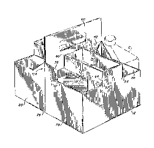
FIG. 5 is a pictorial view of a carrier formed in
accordance with the invention; and
FIG. 6 is a top view of the carrier of FIG. 5, shown with
rectanKular containers in the cells thereof.
Description of the Preferred Embodiment
Referring to FIG. 1, a production blank 10 having a main
body po~tion of ~enerally rectangular shape, the inside surface of
which faces the viewer, comprises a side panel l2 connected by fold
lines 14 and 16 to end panel sections 18 and 20, respectively.
Similarly, a second side panel 22 is connected by fold lines 24 and
~,5~
26 to end panel sections 28 and 30, respectively. End panel
sections 18 and 28 are connected by fold lines 32 and 34 to riser
panel sections 36, while end panel ssctions 20 and 30 are colmected
by fold lines 38 and 40 to riser panel sections 42. The fold lines
14 and 24, 16 and 26, 32 and 34, and 38 and 40 are aLi~ned to allow
folding, as will be explained hereinafter.
The side panels 12 and 22 have centrally located
rectangularly shaped projections 44 and 46, respectively. Partition
straps 48 and 50 are connected to the side ed~es of the projection
44 along fold lines 52 and 54, and partition straps 56 and S8 are
connected to the side ed~es of the projection 46 along fold lines 60
and 62. The opposite ends of partition straps 48 and 56 are
connected along fold lines 64 and 66 to an outer center support
panel section 68. Similarly, the opposite ends of partition straps
50 and 58 are comlected along fold lines 70 and 72 to an inner
center support panel section 74. ~ fold line 76 separates the two
riser panel sections 36 and the two outer center support panel
sections 68 and divides the generally rectangular portion of the
blank 10 in two. The riser panel sections 36 are mirror ima~es o~
each other, as are the outer center support panel sections 68,
enablin~ the sections to be folded upon each other as described in
more detail hereinafter. A fold line 78 also divides the riser
panel sections 42 and the inner center support panel sections 74 in
the same manner as fold line 76, the fold lines 76 and 78 being
aligned. The outer and inner support panel sections contain handle
openill~s 80 and 82 on opposite sides of the fold lines 76 and 78 to
permit a handle opening to be fot~ed in the finally formed multi-ply
center support panel as explained below.
Partition straps 48 and 56 are separated from the outer
center support panel sections 68 by slits 84, and from end panel
sections 18 and 28 and side paneLs 12 and 22 by slits 86. The slits
86 also extend beyond the fold lines 64 and 66 and angle toward each
other until they terminate at the fold lines 32 and 34. The angled
slit portions are part of the top edges of the end panels of the
carrier formed from the blank. In like manner, partition straps 50
and 58 are separated from inner center support panel sect;ons 74 by
slits 88, and from end panel sectiolls 20 and 30 and side panels 12
5~7~ -
and 22 by slits 90. As i.n the case of the slits 86, the slits 90
extend beyond the fold lines 70 and 72 and angle toward each other
until terminating at the fold lines 38 and 40. The angled portions
of slits 90 are part of the top edges of the opposite end paneLs of
the carrier forl~ed from the blanX. The interior ends of outer
center support panel sections 68 terminate in an edge 92 in the
central portion of the blank 10, and the interior ends of inner
center support panel sections 74 terminate in the central portion of
the blallk in an edge 94 spaced f~om the edge 92. The outer ends of
the outer center support panel sections 68 are foldably comlected to
the fold lines 32 and 34 on either side of the fold line 76. T~le
outer ends of the inner center support panel sections 74 terminate
in a slit 95 which separates the sections 74 from the riser panel
sections 42 on either side of the fold line 78, the slit 9S bein~
ali~ned with the fold lines 38 and 40.
A glue flap 96 is connected to the outer edge of the side
panel 12 by a fold line 98, and bottom panel 100 is connected to the
outer ed~e of the side panel 22 by fold line 102. The bottom panel
100 i5 divided in half by score line 104 to form two bottom panel
sections 106. The bottom panel may be notched at the ends of the
score line 104 as at 108 for subsequent engagement with hooks or
tabs fot~ed from cutouts 110 in the riser panel sections. I'he
bottom panel sections thus are connected so as to extend
transversely of the generally rectangular main body portion of the
blanX.
To form the carrier, adhesive is first applied to the outer
center support panel sections 68 in the stippled area shown in FIG.
1. The inner support panel sections 74 are then elevated out of the
plane of the blank, causing the partition straps 50 and 58 to pivot
upwardly about their fold lines 54 and 62. At the same time the
sections 74 are caused to remain substantially parallel to the plane
of the blank by relative downward pivotin~ movement between the
sections 74 and the fold lines 70 and 72 at the opposite ends of the
partition straps 50 and 58. The end result of these movements is to
pivot the inner center support panel sections 74 so that the outer
surface thereoE is engaged with the stippled inner surface of the
outer center support panel sections 68, the handle openings being
7~ .
aligned with each other as shown in ~IG. 2. The length of the outer
center support panel sections 68 is equal to the len~th of the side
panels 12 and 22, and is ~reater than the length of the inner center
support panel sections 74. The shorter len~th of the sections 74
allows space for the subsequent foldin~ of the riser panel sections
36. Even with this di~ference in length, the outer and inner
support panel sections 68 and 74 are spaced from each other in the
original blank shown in FIG. 1 in order to be able to form cells
which can receive articl~s that are elon~ated in transverse cross
section.
Still referring to FIG. 2, the next step in the foL~ation
of the carrier is to apply adhesive to the stippled areas of the
imler and outer center support panel sections 68 and 74, as well as
to the stippled areas of the central portions of the riser panel
sections 36 and 42. The riser panel sections 36 are then folded
along fold lines 32 and 34 so as to en~age the sections 68, and the
end panel sections 20 and 30 are folded along fold lines 16 alld 26
to cause the riser panel sectiolls 42 to engage the inner center
support panel sections 74. A cutout 112 in the inner center support
panel sections 74 along fold line 78 adjacent the edge 95 is ali~ned
with the fold line 78 in the riser panel sections 42 to reduce the
layers of material at this point so as not to interfere with the
subsequent folding process.
The result of this action is illustrated in FIG. 3. 1he
next step in the formation of the carri~r is to apply adhesive to
the stippled areas of the riser panel sections 36 and 42, the center
support panel sections 68 and 74, and the glue strip 96. The
partially folded blank is then folded alon~ fold lines 76 and 78 to
adhere the riser paneL sections together and the center support
panel sections together. In addition, the lowermost bottom panel
section 106 is first folded upwardly about fold line 104 so that the
~lue flap 96 contacts the opposite side of the ed~e portion of the
lowermost bottom panel section after it has been folded up.
These foldin~ and gluing actions complete the formation of
the semi-formed blank, which is shown in FIG. 4. The center support
panel is now Kenerally comprised of four to six plies of paperboard
and the riser panels are comprised of two plies. The partition
straps are not adhered to any structure, but are foldably colmected
at their ends as explained above, the single strap visible in this
view being strap 48. The folded and glued blank may be shipped in
this condition to the packaging facility where the blank i5 opened
to receive articles by applying pressure in an inward directi.on to
the side edges of the blan~. This action squeezes the folded blank
into the carrier fo~ shown in FIG. 5. It should be understood that
the recesses ~10 at the bottom of the riser panels are mated with
the notches 108 at the center eclges of the bottom panel of the
carrier to mechanically support the bottom of the carrier.
As showtl in FIG. 5, the resulting carrier h;ls partition
straps 48 and 50 foldably connected to and extending between the
center support panel 68 and the side panel 12. The straps are
colmected to the vertical edges 52 and 54 o~ the projecting portion
4~ of the side panal so that the straps, which fol.m the side
partitions of the center cell are located above the main body o~
the side panel. The rissr panels 36 and 42 extend a substantial
distance inwardly from the center fold 76 of the end panel sections
18 and 28 to provide added support for the containers C, one of
which is shown in phantom lines. Also, the portions of the elld
panels adjacent the riser panels extend upwardly to fol~ the
triangular portions 114 which terminate at the same height as the
tops of the partition straps and serve to provide added support to
the containers in the end cells. The tL~iangular portions are fotmed
as a result of the angled portions of the slits ~6 and 90 discussed
previously. As shown more clearly in FIG. 6 the cells of the
carrier hold containers C which in the illustrated ~mbodiment are
about twice as long as they are wide.
It should now be clear that the present invention provides
for a carrier adapted to hold containers which are elongated in
cross section. The carrier further is formed from a blarlk of
minim1Jm area, representing a significant cost saving. The foldable
connections between the partition straps and the center support
panel sections are located between the side panels and the riser
panel sections and the opposed edges of the center support panel
sections are spaced a substantial distance apart, providing for a
`'7~
finished carrier with cells significantly longer than they are wide.
It should now be obvious that although a preferred
embodiment of the invelltion has been described, changes to specific
detai.ls of the embodiment can be made without departing from the
spirit and scope of the invention as defined in the appended claims.