Note: Descriptions are shown in the official language in which they were submitted.
~J~3~j 3~
PRESSURE ACTIVATED ISOLATION VALVE
BACKGROUND AND SUMMARY OF INVENTION
The present invention is generally related tv to a
pressure activated isolation valve for use in
anti-lock~traction control braking systems.
In many instances it is considered desirable to
10 isolate the brake pedal from the operation of the
anti-lock and/or traction control system. This
isolation is desirable so that these systems do not
interfere with normal brake pedal operation. As an
e~ample it is undesirable for an anti-lock system to
15 feed back to the brake pedal to cause it to move Erom
the position established by the operator. Simi]arly it
is undesirable for a traction control system to activate
the brakes of the non-driven wheels. As such, it is
desirable to incorporate into such systems an isolation
20 valve. Prior systems have suggested using solenoid
valves to isolate the anti-lock system from the brake
pedal andJor from the master cylinder. Without such
isolation the vehicle operator may become distracted at
inopportune moments due to une~pected movement of the
25 brake pedal. However, the inclusion of the solenoid
valves and associated wiring to accomplish the isolation
function increases cost, and may lower the overall
reliability of the system.
It is a purpose of the present invention to provide
means which obviates the need for solenoid valves to
achieve the desired isolation of the master cylinder
from the remainder of the anti-lock/traction braking
system. Another purpose of the present invention is to
~k
35
--2--
provide an anti-lock/traction braking system which uses
pressure activated isolation valves. A further purpose
of the present invention is to provide means for
automatically preventing the operation of the isolation
5valve(s) if adequate pressure is not available for
reapplication of brake force (after release) during
anti-lock system operation. An additional purpose of
the present invention is to utilize many of components
of an anti-lock system to control tractive effort.
Accordingly the invention comprises: a pressure
responsive isolation valve for use within an adaptive
braking system comprising: passage means including a
first port adapted to receive pressurized fluid from a
15first pressure source, an outlet port adapted to
communicate with various brake cylinders, a second port
adapted to communicate fluid to or from control valves;
and a pressure port remote from the other ports, adapted
to receive pressured fluid from a second pressurized
20source. The isolation valve further includes: valve
means movable to open and close one or another of
opposingly situated passages and to alternatively
communicate the first port to the outlet port or the
second port to the outlet port; means for moving the
25valve means relative to the passages, including first
means movable in response to pressurized fluid from the
second source for urging the valve means to seat upon
the first passage to control communication to and from
the first source to the output port.
Many other objects and purposes of the invention
will be clear from the following detailed description of
the drawings.
~2 ~6~? 3~;j
Brief Description of the Drawings
In the drawings:
FIGURE 1 schematically represents a two channel
three solenoid anti-skid system which optionally
includes traction control.
FIGURE 2 shows an alternate two channel system.
FIGURE 3 shows a detailed view of one of the
isolation valve of FIGURE 1.
FIGURE 4 is a cross-sectional view taken through
section 4-4 of FIGURE 3.
FIGURE 5 shows an alternate emboderment of a spring
used in the isolation valves.
Detailed Description of the Drawings:
FIGURE 1 illustrates a two-channel, three solenoid
anti-skid/traction control braking system 16 for
controlling the motion of the various wheels 18 of a
vehicle. The system 16 comprises first means for
25increasing the brake fluid pressure in response to
operator demand. Such first means may include a master
cylinder 22 having respective pressure chambers 24 and
26 each of which are communicated to a fluid reservoir
2~. A drive link 30 is attached to the brake pedal (not
30shown) in a known manner. As illustrated in FIGURE 1
the master cylinder 22 may be activated by a power
assist mechanism such as a vaccuum power booster which
is schematically shown as 32.
~L;2~3G~S`3~
The system 16 further includes an electronic
control unit (ECU), generally designated as 40,
responsive to signals (Sl-S ~ indicative o~ the
rotational state of each wheel 18. A pump 50 is used to
provide additional brake fluid under pressure and
includes an output 52 and an input 54. As illustrated
in FIGURE 1 the pump is driven by an electric motor 56
in response to a control signal generated by the ECU 40
The system further includes brake means, responsive
to fluid pressure for slowing the rotation o~ selective
wheels 18. As illustrated, the system includes a
plurality of brake cylinders 62a-d one each associated
with each wheel 18a-d. As it is known in the art these
brake cylinders form part of typical disc brakes or
foundation brakes. Associated with each of the wheels
is a wheel speed sensor and tone wheel for generating a
series of pulses indicative of the rotational speed of
particular wheel. Such wheel speed senors and tone
wheels are not illustrated in FIGURE 1 since such
devices are standard in the art of adaptive or anti-lock
braking systems. For convenience of description the
braking means is divided into two substantially
identical braking channels 64a and b. As illustrated in
FIGURE 1 the braking channel 64a and b are split braking
channels. As an example, braking channel 64a may
comprise one front wheel brake cylinder 62a and a
diagonally situated rear wheel brake cylinder 62c. The
braking channel 64b includes the remaining brake
cylinders 62b and d. It should be appreciated that each
braking channel includes the corresponding tone wheels
and sensors for each of the respective wheels.
Obviously, other splits between the brake cylinders can
be used such as a front-to-rear split.
The output 52 of the pump 50 is communicated to
separate regulator means 70a and 70b, one for each brake
channel 64a and 64b. As illustrated, such regulators
70a and b are of the differential pressure regulator
5type responsive to the pressure level established by the
pump 50 as well as to the pressure level established by
the respective chambers 24 and 26 of the master cylinder
22. The purpose of the differential pressure regulators
is to maintain the pressure at their respective outputs
72a and 72b at approximately the pressure level within
the chambers of the master cylinder as established by
the operator. The system can also be configured with a
single regulator.
A first valve, such as solenoid valve 80a,
responsive to a control signal generated by the ECU 40,
is located in fluid communication with the output 72a of
the first pressure regulator 70a. The first solenoid
valve 80a includes a first port 82a, second port 84a and
20a third port 86a. In the absence of a control signal
received from the ECU 40 the first and second ports 82a
and 84a respectively, are communicated to each other
through a control orifice 88a. The second port 84a is
communicated to a first port 92a (part of an alternate
25flow path) of a first pressure responsive isolation
valve 90a. The third port 86a of the solenoid valve 80a
is communicated to the reservoir 28. When in receipt of
a control signal from the ECU 40 the internal valving of
the first solenoid valve communicates the second port
3084a to the third port 86a.
As mentioned above, the isolation valve 90a is a
pressure responsive valve and more particularly, is
responsive to the pressure level establishea by the pump
~ ~6~
50 which is received at port 98a. The isolation valve
further includes ports 94a and 96a. Port 94a 'is
communicated to one of the chambers, such as chamber 24
in the master cylinder 22 and port 96a is communicated
sthrough a brake line lOOa to the brake cylinders within
the first braking channel 64a. The isolation valve 90a
further includes a bias spring lOla for biasing the
isolation valve 90a against the fluid pressure
established by the pump 50. When the fluid pressure of
the pump 50 is below a first pressure level the
isolation valve will be in a condition as shown in
FIGURE 1 wherein the master cylinder chamber 24 is
communicated directly to the brake cylinders in the
first braking channel 64a through ports 94a and 96a
15reSPeCtively. As described below, the pressure
generated by the pump 50 will increase as the motor 56
turns in response to a control signal generated by the
ECU 40. As the pressure level increases the isolation
valve is moved such that the ports 92a and 96a are
20placed in direct communication thereby isolating the
master cylinder chamber 24 from the remainder of the
braking system and permitting fluid at the output 72a of
pressure regulator 70a to be communicated through the
solenoid valve 80a to the braking channel 64a. The
25isolation valve 90a is shown in greater detail in FIGURE
3.
The system further includes a second valve, such as
solenoid valve 80b, responsive to control signals
generated from the ECU 40, an isolation valve 90b
30communicated with the pump in a like manner as
previously described for isolation valve 90a and
regulator 70b. The pump 50, solenoid valve 80b,
isolation valve 90b and pressure regulator 70b are
connected to and through the second braking channel
.~ :
:1 2!36~35
64b in a manner identical with that described above with
the exception that the isolation valve 90b is connected
to the second chamber 26 of the master cylinder 22.
Each brake channel 64a and 64b typically includes a
proportioning valve llOa and llOb respectively, for the
rear vehicle wheels 18c and d. The proportioning valves
are communicated to the brake lines lOOa and lOOb
through a shuttle valve 112. The shuttle valve is a
Opressure responsive valve having two modes of
operation. The first mode of operation, permits direct
communication of the proportioning valves 110 to the
brake lines 100. The second mode of operation is entered
into in response to an increased pump pressure and
terminates communication between the proportioning
valves and the brake lines. Pressure is communicated to
the shuttle valve 112 from the pump 50 through a third
valve such as an ~lectrically responsive third solenoid
valve 120. The solenoid valve 120 includes ports 122,
2ol24 and 126. The port 126 is communicated to the
outputs 72 of the pressure regulators 70a and 70b
through a like plurality of check valves 128a and 128b.
The purpose of the shuttle valve 112, solenoid valve 120
and check valves 128 is primarily to permit the
25incorporation of a traction control feature in the
present invention. It should be recognized that by
eliminating the shuttle valve, the third solenoid valve,
and the check valves from the system the remaining
structure defines a two solenoid, two channel anti-skid/
30braking system.
FIGURE 1 illustrates the condition of the system
during normal braking operations with the traction
b'J 3~
control portion of the system deactivated. Under normal
braking conditions brake pressure from the master
cylinder 22 is communicated through the isolation valves
90a and 90b to the appropriate braking channels 64a and
s64b. In this mode of operation the performance of the
system is characterized by normal braking. During the
normal braking performance o~ the vehicle the ECU 40
monitors the output of the wheel speed sensors (not
shown) corresponding to each of the wheels 18 of the
vehicle. In response to the signals from the sensors
and to a brake switch signal (m), indicative that the
brake pedal has been applied by the operator, the ECU
determines whether or not one or more of the wheels of
the vehicle are skidding or are approaching an impending
15 wheel skid situation. "Skidding" and "impending" skid
are used synonomously. Upon the application of the
brakes the ECU 40 generates a signal indicative of
average deceleration of the various wheels. When the
average deceleration increases to a predetermined value,
20 such value being indicative of impending or actual skid
the ECU generates control functions to thereby decay
and/or build the pressure within the brake cylinder for
the skidding wheel. If such condition occurs the ECU
additionally provides a signal to activate pump 50.
25 Very quickly after start up of the pump the pressure at
the pump outlet 52 will raise to a sufficiently high
level to overcome the spring bias on the isolation
valves 90a and 90b. For the present example it is
assumed that one of the wheels in the channel 64a has
30 been detected as skidding. The isolation valves change
their state in response to the supplied pressure from
the pump 50 such that ports 96a and 96b are communicated
to ports 92a and 92b respectively. In essence, this
change in the operational state of the isolation valves
6G 3~
90a and 90b isolates the master cylinder from the
remaining portion of the system and maintains the
pressure within the master cylinder 22 to a value
sufficiently high that the operator of the vehicle
ssenses that full brake pressure is still being supplied
to brake cylinders 62a-d. With regard to the
non-skiddinq wheels of braking channel 64b, it is
desired that normal braking continue for these wheels.
This is accomplished by controlling the brake cylinders
62b and 62d through the brake pressure developed at the
output of pressure regulator 70b. As previously
mentioned, the pressure regulator 70b is a differential
pressure regulator and consequently its output pressure,
at port 72b, will be substantially equal to the value of
fluid pressure within the master cylinder chamber 26.
Such pressure is communicated to braking channel 64b
through orifice 88b within solenoid valve 80b via the
isolation valve 90b.
With regard to the control of the braking channel
64a, which includes the skidding wheel(s), and as
mentioned above, the ECU generates a control (decay)
signal to the first solenoid valve 80a causing same to
change its state thereby communicating the first
25isolation valve 90a to the reservoir via ports 84a and
86a. It should be apparent from the above that by
communicating the various brake cylinders, within
braking channel 64a to the reservoir ~8, through the
isolation valve 90a and solenoid valve 80a the brake
30pressure within the brake cylinders 62a and 62c is
permitted to decrease. During this mode of operation
the ECU 40 continually monitors the rotational state of
the wheels and when it senses that the acceleration of
the locked or skidding wheel is zero or positive
~L2~ 35
--10-
(indicating that the wheel has begun or is just about to
rotate) the ECU 40 removes the control signal (which
causes solenoid valve 80a to change state) thereby
reestablishing communication between ports 82a and 84a.
5In this mode of operation the fluid pressure established
at the output of the differential pressure regulator 72a
is communicated to the brake cylinders within braking
channel 64a through the isolation valve 90a and through
the orifice 88a within the solenoid valve 80a. The
orifice 88a reduces the rate of the pressure rise to the
s~idding wheel(s) to avoid immediate and premature wheel
lock-up. As the regulated pressure supplied to the
brake cylinders in the braking channel 64a continues to
rise, the ECU 40 monitors the rotational state of the
wheels to determine if the re-applied pressure has again
caused the wheel to reenter the locked condition
whereupon the control signal to solenoid valve 80a is
applied thereby dumping or relieving the brake pressure
to the reservoir, permitting the locked wheel to again
20reaccelerate. Thereafter, the control signal is again
removed and pressure is supplied to the brake cylinders
through the orifice 88a. The above conditions are
continued until the wheel skid condition has terminated
and the ECU 40 removes the control signal to the pump 50
25which causes both of the isolation valves 90 to assume
their normal non-anti-lock position and reestablishes
normal brake control between the master cylinder and the
various wheel cylinders.
The following is a description of the operation of
the traction control portion of the system described in
FIGURE 1. The traction control portion is operated
independently of the anti-skid portion of the system.
The purpose of traction control is to maintain the
.~
:
,....... .
difference in the rotational velocities of the driven
wheels at a predetermined level. The operation of the
traction control system is best understood by the
following example where it is assumed that the vehicle
Sis at rest having one of the driven wheels on a low
coefficient of friction surface. Typically in response
to increases in the engine throttle, all of the engine
power is communicated to the wheel on the lowest
coefficient surface, as such, such wheel un~ontrolla~ly
rotates, providing less than desired vehicle motion.
Typically, the driven wheels are supplied torque through
a differential. The differential always provides egual
torque to each wheel (except for friction or inertial
effects). Therefore, the torque transmitted to the
15slower wheel is limited to the torque transmitted to the
wheel on the lowest coe~ficient surface. As mentioned
above, in response to increased throttle the vehicle
will still not move and only engine spee~ increases.
Applying the brake to the spinning wheel will slow the
20spinning wheel thereby increasing the torque transmitted
through the differential to the other wheel. The
traction control system is activated when the brakes are
not manually applied. A signal indicative of the
condition of the brakes may be obtained in a norm~l
25manner from a brake switch of a known variety. During
such no-brake condition the ECU compares the rotational
velocity of the driven wheels. As an example, in a
front wheel drive vehicle the ECU 40 will compare the
rotational velocities of each of the front wheels. Upon
30determining that a difference in velocity exists which
exceeds a predetermined minimum, the ECU generates a
control signal to the pump 50. The increased pressure
from the pump 50 is communicated to the isolation valves
90a and 90b causing them to change state. The pump is
:~2~
-12-
also cornrnunicated to a third or traction solenoid valve
120. As can be seen, the output port 126 of solenoid
valve 120 is communicated to the shuttle valve 112 as
well as to the check valves 128a and 128b. During the
Sa~ove described anti-skid operation of the vehicle, that
is with solenoid valve 120 deactivated, the output port
126 is comrnunicated to the reservoir 28. This
communication causes a pressure differential across the
check valves 128a, 128b thereby isolating the traction
control system from the anti-skid portion of the
system. In response to a control signal generated by
the ECU 40, the solenoid valve 120 is caused to change
state thereby cornmunicating its ports 122 and 126 to
permit the fluid pressure generated by the pump 50 to
15cause the shuttle valve 112 to change its state to a
no-flow condition. As can be seen from FIGURE 1 the
shuttle valve 112 has two states. The first operational
state, illustrated in FIGURE 1, is active during the
anti-skid mode of operation wherein brake fluid is
20permitted to flow through the proportioning valves 110
to the various wheel cylinders. In the second mode of
operation, that is, the mode active during traction
control, brake fluid communication is terminated to the
non-driven wheels which, upon reflection, is desirable
2ssince the purpose of the traction control system is to
enable the vehicle to move forward and as such, if
undesired brake application occurs the purpose of the
traction control system is defeated. During instances
when the solenoid valve 120 is activated the output of
30the pump 50 is also comrnunicated through the check
valves 128a and 128b to the wheel cylinders 62a and 62b
through the orifices 88a and 88b in solenoid valves 80a
and 80b. To prevent brake pressure to the non-spinning
driven wheel its solenoid valve 80a or 80b, as the case
i$~5
J.~JL
-13-
may be, will also be actuated to prevent brake
application.
More specifically, the ECU 40 causes the solenoid
svalve, such as solenoid valve 80a corresponding to the
lower rotating non-spinning driven wheel to change state
thereby communicating its port 84a to the reservoir
through port 86a. This action effectively prohibits
braking fluid from being communicated to this low
velocity wheel. With regard to the control of the
higher rotating wheel no additional control signals are
necessary since with the solenoid valve 80b in its
non-activated condition the fluid from the pump 50 is
communicated through check valve 128b to the wheel
15cylinder 62b through the orifise 88b and isolation valve
90b. This action causes the activation of the wheel
cylinder thereby braking or reducing the rotational
motion of the skidding wheel. The benefit of utilizing
the orifice 88b within solenoid valve 80b prohibits an
20abrupt change in brake pressure thereby avoiding a
premature lock-up of the high speed wheel. As mentioned
above, by slowing the spinning wheel engine torque is
transmitted to the other driven wheel.
It should be apparent from the above that the
anti-lock system described in FIGURE 1 modulates the
brake pressure to the skidding wheel so that the brake
pressure is either building or decaying under the
control of the respective solenoid valves 80a and 80b.
30The system described in FIGURE 2 illustrates an
alternate two channel, anti-skid/traction control
system. As may be recalled from the discussion of the
system of FIGURE 1 after the brake pressure of the
skidding wheel has bsen lowered to a level wherein the
~L2~
wheel deceleration has been reduced to zero or
alternatively the acceleration increases (which is
indicative of the fact that the wheel has begun to
rotate and hence is no longer skidding) the ECU ~0
5causes solenoids 80 to reapply the brake pressure
through the various orifices 88. In certain instances,
it is desirable not to immediately increase the brake
pressure to the previously skidding wheel after it has
hegun to reaccelerate. This is accomplished by adding
an additional feature to the system which allows the
brake pressure to be held at a fairly constant value to
permits the previously skidding wheel to reaccelerate.
The anti-skid/traction control system of FIGURE 2 has
many of the components illustrated in FIGURE 1. It
15should be noted that like components are shown with the
same numeral used in FIGURE 1. In the system of FIGURE
2 the solenoid valves 80a and 80b are each replaced by
two sets of solenoid valves, 150a and 152a and 150b and
152b. One of the purposes of the solenoid valves 150a
20and 150b is to permit the reapplication of brake
pressure to the skidding wheel's brake cylinder and as
such they are also referred to as build valves or build
solenoids. One of the functions of the solenoids 152a
and 152b is to permit pressure in the various wheel
25cylinders to decay and similarly these solenoids 152 are
also referred to as decay valves or decay solenoids. In
addition, the solenoids 150a, 152a, 150b and 152b
cooperate to fix or maintain the brake pressure to the
previously skidding wheel and in concert these pairs of
30solenoid valves cooperate to perform a hold function.
Each of the sol~noid valves 150 and 1~2 is shown
schematically and includes two operational modes, a
closed mode and an open mode which respectively permits
or prohibits fluid flow therethrough. As shown in
_ J~ 6
-15-
FIGURE 2, the solenoid valves 150 and 152 are normally
closed (no flow~. The initial functional operation
system of FIGURE 2 is substantially identical to the
initial operation of the system described in FIGURE 1,
sthat is, upon the application of the brakes the ECU 40
generates a deceleration signal indicative of the
rotational state of the various wheels. When such
deceleration increases to a predetermined value, such
value being indicative of impending or actual skid the
ECU generates a plurality of control functions to
thereby decay, hold and build the pressure within the
brake cylinder for the skidding wheel. As an example,
it is again assumed that one of the wheels in the
braking channel 64a is skidding or at an impending skid
situation. The pump 50 is activated as described above
thereby causing the isolation valves 90a and 90b to
change their respective operational states. In order to
correct the skidding condition the ECU 40 generates a
signal to the decay valve 152a, which was previously
20closed (no flow~, causing it to change state thereby
providing a flow path from the skidding wheel's brake
cylinder to the reservoir 28, in order to reduce the
brake pressure in the wheel brake cylinder. The ECU
thereafter monitors the rotational state of the
25previously skidding wheel to determine when that wheel's
acceleration is zero or positive. At this point in time
the control signal is removed and the decay valve 152a
closed (no flow) to prohibit a further decrease in brake
pressure. Upon closing (no flow) the decay valve 152a
30and with the build valve 150a also in a closed (no flow)
condition, fluid pressure within the skidding wheel's
brake cylinder cannot increase or decrease and is
maintained or held at the level of brake pressure
sufficient to permit the wheel to reaccelerate. After
9~-3~
the previously skidding wheel has accelerated
sufficiently, the ECU generates another control signal
to the build valve 150a thereby opening (flow) same to
communicate the output of the differential pressure
5 regulator 70a to the skidding wheel's brake cylinder
through the isolation valve 90a thereby increasing the
brake pressure to controllably slow the rotational speed
of the wheel. The rate of change of this reapplied
brake pressure is controlled through an orifice 154a
]Oformed within the build valve 150a as well as by
duty-cycle modulation of the valve. Depending upon the
control philosophy used by the ECU 40, the build valve
150a may be maintained opened (flow) or alternatively
may be pulsed between open and closed conditions to
15permit the brake pressure to gradually increase. If the
reapplied brake pressure communicated through the build
valve 150a is sufficient to cause the previously
skidding wheel to again enter into a skid condition the
ECU terminates the control signal to the build valve
20thereby prohibiting additional buildup of pressure, and
essentially simultaneously reactivates the decay valve
thereby decreasing the brake line pressure. The above
functions of decay, hold and build of the brake pressure
are continued until the previously skidding wheel has
25been brought unaer control. The operation of the
traction control portion of FIGURE 2 is similar to that
of FIGURE 1. As before the pump pressure is
communicated throught the solenoid valve 120 and to the
check valves 128. The build and decay valves 150b and
30152b of the slower rotating wheel remain non-activated
to prevent brake pressure build-up. To slow the motion
of the higher rotating driven wheel e.g. 18a, the build
valve 150a is activated by the ECU 40 thereby
communicating the pump 50 to its brake cylinder 62a
3~
through the isolation valve 90a slowing same. Further
the level of pressure can be controlled by also
activating the decay valve 152a.
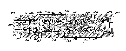
FIGURE 3 illustrates a detailed cross-section of
one of the isolation valves. The isolation valves 90a
and b are identical. The isolation valve 90a includes a
housing 200 having a stepped bores 202a and 202b
therethrough. Situated proximate the middle of the
10 valve is the port 96a which is adapted to communicate
with certain of brake cylinders 62. The port 96a
terminates within the housing at annular passage 204.
Situated within the passage is a ball 206 supported
within a ball cage 208. The ball 206 is axially movable
15 to selectively close a first 220a and a second passage
220b. The first and second passages are formed within
opposingly spaced valve seats 224a and 224b. Each valve
seat is received within an insert 228a and 228b.
Each insert is substantially identical and includes
a necked-down portion 232a, 232b which form in
cooperation with the housing 200 fluid annuli 234a and
234b. A port such as port 94a communicates the annulus
234a with a chamber of the master cylinder 22. Another
25 port such as port 92a communicates the annulus 234b with
a solenoid valve such as valves 80, 150 or 152. The
inserts 228a and b include first bores 240a, 240b
respectively, which receive at one end thereof the valve
seats 224a or 224b. The other end of each insert
30 includes a cross-hole 242a or 242b to communicate the
first bores 240a,240b with its respective annuli 234a or
234b. Oppositely positioned from each first bore 240 is
a second bore 250a,250b. Each first and second bore is
separated by a member 252a,252b which radially extends
~ ;~g~ 3~
-18-
inwardly and terminates at an opening 254a,254b. A
pressure equalization passage 256a,256b connects each
second bore 250a, 250b with its corresponding annulus
234a,234b. Extending through each insert is a rod 260a
sor 260b which extends through the passage 220a or 220b
to selectively bias the ball 206 against the passages
200a or 220b closing same. The rod 260a is radially
stabilized by an O-ring retainer 262 having an opening
264. The retainer 262 also functions as a guide for the
rod 260a. Received within the second bore 250b of the
insert 228b is a rod guide 268. The rod guide 268
includes a narrow opening 270 through which the rod 260b
extends. The rod guide 268 terminates at a flanged end
272 having cross-slots 274 formed on a face thereof.
The cross-slots 274 are shown in FIGURE 4. As
mentioned, the O-ring retainer 262 and rod guide 268 are
received proximate the outer end of its corresponding
second bore 250a,250b. Also received within each second
bore 250a, 250b about each rod 260a,260b is an O-ring
20276a, 276b and back-up ring 278a, 278b.
Referring again to the rod guide 268 its flanged
end terminates short of the walls of the stepped bore
202. Received within the stepped bore 202b is a piston
25housing 280. The piston housing 280 terminates in a
tapered end 282 at the rod quide 268 and forms in
cooperation with the bore 202b and guide 268, an outer
annulus 284. An inner annulus 287 is also formed
between the piston housing 280 and the rod 260b. The
piston housing 280 includes a bore 285 for receipt of a
piston 286. The piston 286 may be formed integral with
or separate from the rod 260b. The piston 286 includes
a partial bore 2~8 for xeceipt of a spring 290 which
biases the piston 286, and rod 260b against the ball 206
35thereby urging same in the direction of passage 220a.
~ 29~35
--19--
The spring 290, piston 286, piston housing 280 are
secured within the housing 200 by spring retainer or end
cap 292 and the threaaed retainer 294.
Formed within the housing 200, proximate the
annulus 234b, is the port 92a communicated to the
various solenoid valves. Also formed within the housing
200 is the supply port 98a which is connected to the
pump and a vent port 324 adapted to be communicated to
the reservoir 28 for providing a low pressure leakage
path. The partial bore 288 of the piston 286 is
communicated to the supply port via cross-holes 302 and
a groove 304 formed in the piston housing 280.
An end 310 of the rod 260a extends out from the
insert 228a and is received within a rod cap 312. The
rod cap 312 includes a radial flange 314 for receipt of
spring 316. Another end cap 320 secures the rod cap
312, spring 316, rod 260a, etc., in place and may also
20include an air vent 321.
The spring 316 urges the ball 206 to the right as
viewed in FIGURE 3, to close off passage 220b. The end
310 of the rod 260a is received within an oversized bore
2~322 which eliminates misalignment problems between the
rod cap 312 and rod 260a. A ball 323 is located in the
bore 322 and functions as a seat for the rod 260a.
During non-anti-lock operation, i.e. with pump 50
30deactivated, the spring 316 urges the ball 206 off from
the passage 220a, thereby providing a flow path from the
master cylinder to the brake cylinders through ports 94a
and 96a. During periods when the pump 50 is active,
pump pressure is supplied to the piston 286 via port
3598a, which in turn, causes the piston to urge the ball
~2:36~3~
-20-
206 to close passage 220a, thereby isolating the master
cylinder ~port 94a) from the brake cylinders. The
movement of the ball also opens passage 220b permitting
flow to ana from the brake cylinders via ports 92a and
596a.
Upon subsequent deactivation of the pump 5G, the
spring 316 again seats the ball 206 closing passage 220b
to allow direct communication between the master
cylinder and the brake cylinders i.e. between ports 94a
and 96a.
Reference is now made to FIGURE 5 which illustrates
an alternate embodiment of the invention. More
15specifically, there is illustrated a spring 316a
suitable to replace spring 316. Spring 316 as shown in
FIGURE 3 may be a linear spring. As such, upon the
application of pump pressure to the isolation valve the
ball 206 will be moved in a relatively linear manner
20from passage 220b to passage 220a to isolate the master
cylinder as described above. Spring 316a is a snap
spring comprising upper and lower members 350 and 352 of
a general cylindrical shape. Extending between the
upper and lower members about the circumference thereof
25are a plurality of spaced ribs or fingers 354 which may
be formed integrally with members 350 and 352. In
operation, the lower member 352 is received about the
rod cap 312 and urges same toward the ball 206. The
snap spring 316a prohibits the linear movement of the
30ball toward passage 220a. The snap spring 316a
continually urges the ball against passage 220b until
the fluid pressure applied to the piston 286 reaches a
specified level. At such time the fingers 3S4 rapidly
deform, snap or buckles outwardly permitting the spring
35316a to compress. This action permits the ball 206 to
36~35
2 _ J L
-Zl
transition from passage 220b to passage 220a almost
instantaneously.
Many changes and modifications in the above
described embodiment of the invention can, of course, be
carried out without departing from the scope thereof.
Accordingly, that scope is intended to be limited only
by the scope of the appended claims.