Note: Descriptions are shown in the official language in which they were submitted.
1296S97
TUB TRANSFER-DIVERTER VALVE WITH BUILT-IN VACUUM BR~AKER
AND BACK-FLOW PREVENTER
FIELD OF THE IDVENTION
This invention is for a tub transfer-diverter valve with
built-in vacuum breaker and back-flow prevention means. It is
particularly useful in plumbing fixtures where diversion of fluid
flow is required between a spout and a hand spray or shower. The
valve assembly comprises a single unit to be mounted on the deck or
flange of a tub, bath or similar fixture, thus permitting easy
installation and service.
BACKGROUND OF THE INVENTION
Diverter valves have been known for some time for a variety
of purposes. They are well known for use with bidets, tub-shower
combinations and whirlpools. In bidets, the water flow may be
diverted from the rim of the bidet to a spray outlet located towards
the front of the bidet. In tub-shower combinations, diversion is
from the tub spout to the shower, with the normal flow being to the
tub spout. The use of back-flow preventers or vacuum breakers in
such diverter valves is known in order to prevent contamination of
the potable water supply. This becomes particularly important in
the case of tub spout-hand shower assemblies where the hand shower
may be placed in contaminated water during use.
There ha~ already been described in U.S. Patent ~o.
4,589,438 issued May 20, 1986 to Silvano Breda a diverter valve for
use in a tub transfer assembly which valve comprises a main body
chamber with inlet and outlet openings, a centrally disposed
vertical inlet tube having a floating vacuum breaker assembly at its
remote end, movable in response to changes in flow direction and
pressure; the main chamber having another cylinder mounted therein
with lateral openings, which openings may selectively engage the
lateral outlet openings of the central chamber to permit flow
thereto from an inlet opening.
U.S. Patent No. 3,180,352 discloses an anti-siphon,
non-spill valve. Water does not spill out an air vent because a
1296597
combine check and float valve is used in the structure. Upper and
lower valve seats are provided for the valve to ensure closure of
the air vent.
A double seat valve cone is employed in a diverter assembly
disclosed in U.S. Patent No. 4,224,962 wherein flow is transferred
from a tub to a shower. The valve is spring biased for flow to the
tub and is designed for extremely low operating pressures.
Connected parts move independently of each other through an extended
valve stroke which would seem to contribute to the low pressure
sensitivity of the system.
U.S. Patent No. 4,326,671 discloses an anti-siphon valve
and diverter for use in a water sprinkling system.
U.S. Patent No. 3,144,873 discloses a dishwashing device
which incorporates a diverter valve for transferring fluid flow
between a spray and a spout (first and second outflow passages).
The device includes a total of three back-flow prevention means or
valves. The first is a flexible valve ring which is automatically
sucked against a plurality of inlet bores when pressure in the inlet
falls below atmospheric pressure. This places a diverter chamber,
through a bypass bore and first outflow passage, in communication
with atmosphere via a spout. The second check valve comprises a
flared skirt or valve which expands and contracts against a wall in
response to reverse flow in the device. The third check valve is
located in a tube which is remote from the main assembly.
Thus, although the prior art does disclose assemblies which
incorporate both diverter and back-flow or vacuum breaker means,
there does not appear to be available commercially a well designed
tub transfer diverter valve assembly which is reliable, easily
manufactured, installed and serviced, and which also permits
flexibility of installation with respect to location and variety of
aesthetic finishes. In practice, such assemblies should have good
flow rates without leakage through any of the back-flow or vacuum
breaker means. The assembly should also include a back-flow
preventer means which will permit the clearing out of standing water
1Z96597
from the assembly when the tub spout is positioned at a point higher
than the point at which the transfer valve is located. The
provision of a structure combining all these functions in one unit
would clearly be highly desirable from the commercial point of view,
since it would help reduce inventory requirements.
SUMMARY OF THE INVENTION
Thus, the present invention provides a valve assembly
comprising a main body housing having at least one fluid inlet and
at least two fluid outlets, flow paths associated with each of the
inlets and outlets, and passages connecting the inlets and
associated flow paths to the outlets and associated flow paths, one
such passage being open to atmosphere; a diverter valve for
transferring flow from one inlet to one or another of the outlets
and comprising a hand actuated diverter rod connected to a bicone
washer biased in a first position whereby fluid flows from an inlet
to a first outlet and the second outlet is closed and sealed, and on
actuating the diverter rod, the bicone washer is moved to a second
position where it is maintained by pressure of fluid flow from the
inlet to the ~econd outlet and the first outlet is closed and
sealed, and flow thereto ceases; a back-flow preventer/vacuum
breaker valve located in the inlet flow path and a connecting
passage, and movable, in response to changes in fluid flow direction
or atmospheric pressure, from a first position, whereby back-flow is
prevented as the valve closes and seals the inlet flow path, and
opens the connecting pasqage outlet to atmosphere, to a second
position in response to fluid flow from the inlet, whereby the
connecting passage outlet to atmosphere is closed and sealed against
fluid flow, the valve being normally located in the first position
and returnable thereto with changes in fluid flow pressure and
direction or atmospheric pressure; the valve having a truncated cone
shape with an upper flange, guide means on each valve end and
sealing means at each end to engage valve seats at the upper and
lower limits of the path of travel of the valve; a back-flow
preventer valve located in the first outlet flow path movable from a
1Z9~;597
first position in which the valve is normally biased, whereby the
inlet flow path is closed and sealed against flow, to a second
position in response to fluid flow from the inlet path, the valve
being of spindle-like shape with a whorl-like base having guide
means and sealing means associated with it, and upper valve seat
means to engage the valve sealing means.
Generally, the valve assembly will comprise one fluid inlet
and two fluid outlets. The fluid inlet may be attached to separate
hot and cold water supplies or a mixed supply line. The outlets
preferably comprise a tub spout and a hand shower, but a wall shower
could also be connected either in preference to the hand shower or
in addition to the hand shower. In the latter instance, the
assembly would require three outlets or an additional diverter
device to be added to the shower.
The design of the diverter valve is such that it comprises
the rod which may be hand actuated and a bicone washer at the lower
end of the rod. Biasing means, preferably spring means are mounted
on the rod to maintain the rod and hence the diverter valve in the
first position. The diverter valve includes first sleeve means to
retain the rod and biasing means within the assembly, second sleeve
means which include an upper valve seat for the bicone washer and an
outlet and associated passage leading to the connecting passage and
associated second outlet of the assembly. Sealing means are
provided between the first and second sleeve means to prevent flow
above the second sleeve means and additional sealing means are
provided to prevent flow from the outlet of the second sleeve means
to any other part of the assembly but to the second outlet thereof.
On depressing the rod of the diverter valve, the spring is
compressed and the valve moves down from its first position to its
second position where the lower portion of the bicone washer
contacts the lower valve seat provided in the housing and seals off
the outlet to the tub spout, while at the same time opening the
outlet to the hand or wall shower or both. The size of the bicone
washer and the channel in which it moves from its first and second
~296S97
positions are selected so that the valve moves easily up and down in
the channel and the washer and associated valve seat means are such
that a reliable and effective seal is created therebetween. It
should be noted that the passages, inlets and outlets in the
assembly are sized such that substantial flow rates are achieved
throughout. Hence, in use the assembly permits one to fill quickly
a tub or bath or similar fixture. In addition, the flow rate
ensures that when the bicone washer of the diverter valve is
depressed into the second position, the pressure of the fluid flow
or water flow is such that the bicone valve remains in that position
until water flow ceases, which may be accomplished by turning off
the fluid or water source.
The back-flow preventer/vacuum breaker valve located in the
inlet flow path lies within a channel in the housing of the valve
assembly and is sized and shaped for reciprocal up and down movement
within the channel or path. Preferably the valve itself is a
particular æhape, namely a truncated cone shape with an upper flange
portion. Its upper and lower ends each include sealing means and
guide means, the latter being preferably triradial vanes and of a
length such that, when the valve is in the upper position, the ends
of the vanes remain within the lower portion of the passage in the
valve housing body. This ensures that when the valve has to move to
its second or lower position, it does so smoothly and reliably. The
same is true for the vanes which comprise the upper guide means.
The limits of travel of this particular valve are determined by the
positions of the valve seats. The vane structure and the truncated
cone and flange structure of the main body portion of the valve are
such that valve response occurs quickly and reliably. The truncated
shape is particularly advantageous when fluid flow is initiated by
turning on the water supply and water enters the inlet and
associated inlet flow passage of the valve assembly. The truncated
shape provides a large surface area for the water to push against
and hence the change in position of the valve is immediate and
effective. Seal is assured everytime and hence the assembly remains
1296597
watertight in the circumstance where fresh water is introduced into
the assembly, and ensures that no back-flow occurs into the potable
water supply when reverse flow is set up.
The back-flow preventer valve located in the first outlet
flow path is biased by means of a spring into a first position
whereby back-flow through the flow path or passage is not
permitted. The spring is selected so that once water is turned on
and flow commences through this outlet, the pressure of the water is
sufficient to move the valve to a second position, hence compressing
the spring. The valve remains in this position permitting flow
through the assembly until the flow is cut off. This valve is
spindle-shaped with a set of upper guide vanes, preferably four in
the shape of a cruciform, with the spindle being of such length that
when the valve is in the open or lower (second) position, the vanes
permit the valve to remain upright. The base of the valve is fluted
and includes a recess for receiving the spring. The valve is
contained within a sleeve or cylinder which threadingly engages an
aperture in the main body of the assembly. The sleeve or cylinder
serves to bias the valve into its normal closed position. In this
way the valve is able to quickly and reliably return to its closed
or first position in which it is normally biased via the spring.
~he spindle-shape and the vanes ensure good flow rates through the
assembly since they permit the valve to remain in a secure upright
position within the passage or channel, thereby providing smooth and
reliable operation. In addition, the shape is such that the valve
quickly responds to any water or spring pressure on it and hence the
valve action or movement is immediate and positive. Sealing means
are provided on the upper portion of the whorl-like base which act
in concert with seating means located at the lower edge of the
channel portion of the body in which the guide vanes move.
The valve assembly body comprises a main body portion in
which the various passages, paths or channels are located. Over
this is found a decorative cover which may be of brass or any
desired material or shape. It is sized such that sealing means
~Z96597
located at the outer surface portions of the main body housing serve
to provide a seal between the two parts. An opening is provided in
the top portion of this covering which provides the vent to
atmosphere for the valve assembly.
The main body portion includes a closing top portion which
includes the top portion of the vacuum breaker/back-flow preventer
valve which is open to atmosphere, providing the vent for the
assembly. The top includes means, preferably set screws by which it
is secured to the body. In addition, there is an aperture or bore
for the hand activated diverter rod. The decorative cover is
mounted over the housing after this closing piece is put in place.
Sealing means are associated with this top closure portion to ensure
that the assembly remains watertight. The exterior of this closure
portion includes sealing means which engage the inner surface of the
outer decorative flange or covering. This ensures a further seal
against leakage for the assembly.
Finally, the structure includes a flange handle or
escutcheon which is mounted on the top of the last mentioned cover
and which includes an aperture and securing means, preferably a set
screw for the diverter rod. A spring cap may be placed on the top
of this flange handle or escutcheon to close it off. Thus, it can
be seen that assembly and disassembly of the unit is relatively
easily accomplished and access to all components is excellent. The
assembly is of course provided with mounting means for securing it
to a plumbing fixture, such as a tub or whirlpool or sink or basin.
The valve assembly is normally made of brass, although
other conventionally known materials may be substituted. All
sealing means, i.e., 0-rings, washers and the like are preferably
made of silicon or rubber materials. The back-flow preventer/vacuum
breaker valve and back-flow valve are preferably made from light and
durable materials. ABS is a good choice for such a material,
although other conventionally known materials may be selected.
lZg6597
BRIEF DESCRIPTION OF THE DRAWINGS
In the accompanying drawings which are meant to illustrate
the invention,
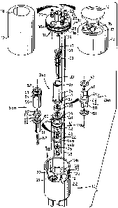
Figure 1 is an exploded perspective view of a tub
transfer-diverter valve assembly according to the present invention;
Figure la is a top view of the interior of the valve
housing with section lines shown thereon for subsequent figures of
the drawings;
Figure 2 is a longitudinal cross-section of the valve drawn
through line 2-2 of Figure la;
Figure 3 is a longitudinal cross-section of the valve drawn
through line 3-3 of Figure la;
Figure 4 is a longitudinal cross-section of the valve drawn
through line 4-4 of Figure la.
DESCRIPTION OF THE PREFERRED EMBODDM~NTS
Referring now to Figure 1 of the drawings there is
illustrated main body housing 10 which is of solid cylindrical
shape, a top surface lOa, is seen in cut-away view. In this
surface, there can be seen a number of apertures including
interiorly screw threaded apertures 22, a substantially larger
interiorly screw threaded aperture 21 and two smooth surfaced
apertures 19 and 20. The top of the body includes an upstanding
hollow cylindrical portion lOb.
The assembly includes a closure 11 for the main body
housing 10; a main body housing cover 12; and a decorative
escutcheon 13, which serves as a handle to actuate a diverter rod
30. Closure 11 for the main body housing 10 includes O-rings 28 and
29 located on its circumferential surface lla, which seal the
housing against fluid flow and leakage and sealingly engage the side
and top of the cylindrical portion lOb of the main body housing 10.
Closure 11 includes an upstanding cylindrical portion 27 which
functionally engages a mating cylindrical projection located inside
decorative escutcheon 13 (see Fig. 2), aperture 30a which receives
diverter rod 30 and aperture 26 which provides the atmospheric
-- 8 --
1296597
opening for the main body housing. Set screws 23 and associated
washers 24 are shown in apertures 25 with the set screws 23, on
assembly engaging the apertures 22 of the main body housing. When
these set screws are tightened, the closure seals the main body
housing 10 against leakage. Over the top of closure 11, main body
hou~ing cover 12 is placed, which contains an aperture 18 through
which the top of the diverter rod is received and which provides the
vent to atmosphere for opening 26. Over the top of the cover 12,
decorative escutcheon 13 which acts as a handle for the diverter rod
30 is placed. The escutcheon is secured to the top of the diverter
rod by means of a set screw 16. The top of the diverter rod is
placed in a hollowed out portion of projection 15 which appears in
the top part of the escutcheon or handle 13. Cylindrical projection
27 frictionally engages a similar cylindrical projection (see Fig 2)
in the interior of escutcheon 13.
Decorative escutcheon and handle 13 are provided with a
spring cap which closes off the mounting for the handle. It will be
obvious from the drawing and this description that many choices can
be made for the escutcheon or handle and thus any type of material
and shape of handle can be used in this particular assembly, thereby
ensuring that the as~embly will find application in many settings
and can be mated with many different types of plumbing fixtures.
This is particularly attractive from the inventory point of view
since it permits one basic assembly to be kept in stock with a
variety of escutcheons or handles to be used therewith.
The lower end of diverter rod 30 includes a screw threaded
portion 33. On the main part of the rod 30, there is located a
spring 32 and retainer ring 31. This assembly fits inside a
cylindrical sleeve 34a which is provided with O-rings 35 and 37.
The O-rings are located at the top and bottom, respectively of the
sleeve. O-ring 37 is located on an enlarged flange portion 36 on
the sleeve, the diameter of which matches the diameter of aperture
20 into which the whole diverter valve assembly fits ~in frictional
engagement) in the main body housing 10. The aperture through
1296597
cylindrical sleeve 34 is such that it is larger at the top end, and
of a size which accommodates the spring and retaining ring 31. The
aperture near the bottom of the sleeve is reduced so that it is
similar in size to the diameter of the diverter rod. Sealing means,
preferably a washer 38 is located in a seat (see Fig 3) in the base
of the sleeve 34. The sealing means, washer 38 ensures that no
water travels up through the sleeve, and hence out of the top of the
assembly. The reduced diameter of the interior of the sleeve
provides a stop for the spring against which it can be compressed.
Another sleeve 40a comprising enlarged top and bottom portions 39
and 41, respectively, each of which carries 0-rings 40 and 42,
respectively, center portion 39a is located below the first
cylindrical sleeve 34. The diameters of enlarged portions 39 and 42
are identical to the diameter of portion 36 of the upper sleeve.
Thus the respective 0-rings 35, 37, 40 and 42 engage the surface of
the respective parts of the passage or channel or paths with which
they are in contact to seal the passage or channel or path, and
hence provide an assembly which does not leak. The narrower portion
39a of the sleeve 40a includes an aperture 39b. The aperture opens
into the sleeve and together with the narrower sleeve portion 39a
provideæ a passage which connects, on assembly, to the second outlet
of the assembly which is preferably connected to a hand or wall
mounted shower. A bicone valve 44 is located beneath lower sleeve
portion 40a, with brass washers 43 and 45, located adjacent its
upper and lower surfaces 44a and 44b, respectively. The upper
surface 44a engages a valve seat 44aa within the base of sleeve 40a,
the seat being shaped and sized to receive the top of the cone in a
manner which provides a seal. A retaining nut 46 is found at the
lower part of the diverter rod assembly and this is screwed onto the
threaded portion 33 of the rod and secures all of the parts of the
diverter valve together. The lower valve seat 44bb for the bicone
valve is found in the base of the aperture 20 in the main body
housing 10. It is again sized and shaped to ensure that a seal is
created between the face 44b and the base of aperture 20. The
-- 10 --
1Z96597
passage with aperture 20 is sized to accommodate the diameter of the
flange 36 or sleeve 34a and the enlarged portions 39 and 41 of the
lower sleeve 40a so that the associated O-rings 37, 40 and 42 form a
seal against the surface of the passage. The upper part of sleeve
34 and O-ring 35 are received within a valve seat associated with
aperture 30a which is not shown since it is formed in the bottom
surface of closure 11.
Back-flow preventer valve and vacuum breaXer 49a is
located in aperture 19 of the main body housing 10. The valve
includes a spool shaped valve 49 which has upper and lower flanges
49b and 49c, respectively. These are sized so that the valve may
operate smoothly in the aperture 19, moving easily up and down
within it. Washers 47 and 51 are provided at the top and bottom of
the assembly and these sit on the top and bottom surfaces of flanges
49b and 49c, respectively. Triradial vanes 48 and 50 are located at
the top and bottom ends of the spool 49. These vanes provide guide
means to ensure that the valve remainE aligned and upright within
the aperture 19 and associated passage. The shape of the valve is
such that changes in water flow direction and atmospheric pressure
easily result in movement of the valve in one direction or the
other. The valve is located in the passage associated with aperture
19, which is the potable or fresh water inlet to the assembly.
Back-flow preventer valve 55a comprises a cylindrical
sleeve portion 55 which is hollow and is provided with external
screw threads and sealing means, preferably an O-ring 53 which helps
secure the valve within the aperture 21. The internal screw
threading of aperture 21 engages the external screw threads 54 of
the cylindrical sleeve. The top of the cylindrical sleeve is formed
into a hexagonal nut or other suitable shape, which permits one to
insert and remove the sleeve easily, and also serves as a stop for
the upper limit of travel of the valve. The valve itself comprises
a spindle 58 and a whorl-like base 59. The top of the spindle is
provided with four vanes in cruciform shape which help guide the
valve in its movement through the passage or aperture 21, which is
-- 11 --
1296597
formed once the sleeve 55 is in place in the body housing 10. An
enlarged flange portion 60 is located at the base of the spindle 58,
on which a washer 57 sits thereby providing a seal. Attached to the
enlarged flange portion 60 is guide means 61 which is of cylindrical
shape, the outer surfaces of which are fluted to permit passage of
water or air to facilitate movement of the valve once in place.
Thus guide means 61 includes bottom opening or recess for receiving
a spring 62 which biases the valve in a closed position. This valve
is located in the outlet to the tub spout, i.e. the main outlet of
the assembly. The spring is selected so that it can be compressed
easily by the pressure of flow of water through the outlet.
Reference should now be made to Figures 2, 3 and 4 which
illustrate cross-sections through the complete assembly as noted
earlier. In Figure 2, the back-flow preventer/vacuum breaker valve
49a is shown at its upper position wherein the vent to atmosphere is
closed and flow is permitted of potable or fresh water into the
system. The valve 49a is located partly in inlet passage 100 and
partly in connecting passage 101. Its path of travel is limited by
the upper and lower surfaces of connecting passage 101 which provide
upper and lower valve seats respectively, against which washers 47
and 51 push to provide either a seal for the inlet 100 or the
atmospheric vent on outlet 26.
In Figure 3, the diverter valve is in its normal position
and the back-flow preventer valve in the tub spout outlet path 102
and connecting passage 103 is shown in open position, as it would be
when compressed by flow of water through the assembly from
connecting passage 101 through to tub spout outlet 104.
Figure 4 shows the diverter valve in closed position or
second position, whereby flow to the tub spout outlet is prevented
and flow to the alternative outlet which may be a handspray or wall
mounted shower is permitted. Thus in this position, water flows
from inlet 100 into connecting passage 101, then through passage 102
into connecting passage 103, where it then flows around the top 44a
of bicone valve 44 and up through the now open sleeve 40a where it
~296S97
exits out of aperture 39b into connecting passage 105 and into
outlet 106 flowing to a hand shower or other device (not shown).
Flow further up the sleeve 40a is prevented by the combination of
washer 38 and the 0-rings 37, 40 and 42 and their respective sealing
surfaces or seat6.
Thus, it will be seen that the valve asæembly provides a
flexible unit which i8 designed for reliable, smooth operation. It
is easily manufactured and assembled. Installation is simple to
accomplish as is maintenance. The replacement of parts is
facilitated by the ready access to all parts of the assembly. The
sealing means and the shapes of the valves all ensure positive and
smooth valving action. Flow rates are excellent through the
assembly.
The scope of the present invention should not be unduly
limited by the choice of particular terminology. Equivalent or
generic terminology may be substituted where appropriate.
Many changes may be made to the embodiment of the invention
illustrated and described herein without departing from the spirit
of the invention. The claims should not be limited unduly to the
illustrated and described embodiment.
- 13 -