Language selection

Search

Patent 1296758 Summary

Third-party information liability

Some of the information on this Web page has been provided by external sources. The Government of Canada is not responsible for the accuracy, reliability or currency of the information supplied by external sources. Users wishing to rely upon this information should consult directly with the source of the information. Content provided by external sources is not subject to official languages, privacy and accessibility requirements.

Claims and Abstract availability

Any discrepancies in the text and image of the Claims and Abstract are due to differing posting times. Text of the Claims and Abstract are posted:

  • At the time the application is open to public inspection;
  • At the time of issue of the patent (grant).
(12) Patent: (11) CA 1296758
(21) Application Number: 1296758
(54) English Title: APPARATUS FOR LIMITING SURGE CURRENTS IN DC-ILLUMINATED INCANDESCENT LAMP
(54) French Title: APPAREIL DESTINE A LIMITER LES CRETES DE COUVRANT DANS LES LAMPES A INCANDESCENCE A COURANT CONTINU
Status: Expired and beyond the Period of Reversal
Bibliographic Data
(51) International Patent Classification (IPC):
  • H05B 39/06 (2006.01)
  • H02H 9/02 (2006.01)
  • H05B 39/02 (2006.01)
(72) Inventors :
  • MASAKI, KAZUMI (Japan)
(73) Owners :
  • KEN HAYASHIBARA
(71) Applicants :
  • KEN HAYASHIBARA (Japan)
(74) Agent: MACRAE & CO.
(74) Associate agent:
(45) Issued: 1992-03-03
(22) Filed Date: 1986-02-20
Availability of licence: N/A
Dedicated to the Public: N/A
(25) Language of filing: English

Patent Cooperation Treaty (PCT): No

(30) Application Priority Data:
Application No. Country/Territory Date
30615/1985 (Japan) 1985-02-20

Abstracts

English Abstract


60-306125
Abstract of the Disclosure
Surge currents which may arise in dc-illuminated incan-
descent lamp can be effectively limited by an apparatus com-
prising a low resistance (first resistance); another resistance
(second resistance); a diode rectifier, the input terminal being
connected in series to an ac source through the first resistance,
and the output terminal being connected in series to an incan-
descent lamp through the second resistance; a voltage regulator
diode connected in parallel with said diode rectifier; a capaci-
tance (first capacitance) connected in parallel to the input
terminal of said diode rectifier; another capacitance (second
capacitance) connected in parallel to the output terminal of said
diode rectifier; a switching device connected to the second
resistance; and a timing circuit connected to said switching
device in a manner that the switching device shorts the second
resistance after a lapse of a prescribed time upon switching-on
of the ac source.


Claims

Note: Claims are shown in the official language in which they were submitted.

THE EMBODIMENTS OF THE INVENTION IN WHICH AN EXCLUSIVE
PROPERTY OR PRIVILEGE IS CLAIMED ARE DEFINED AS FOLLOWS:
1. An apparatus to limit surge currents in a dc-
illuminated incandescent lamp, comprising:
(a) a first resistance with a resistance value that is
large enough to prevent arc discharge in said dc-illuminated
incandescent lamp if its filament is broken;
(b) a second resistance with higher resistance value
than said first resistance;
(c) a diode rectifier, having input terminals for
power input thereto that are connected in series with a power
ac source through said first resistance, and output
terminals that are connected in series with an incandescent lamp
through said second resistance, for providing power for
illuminating said incandescent lamp;
(d) a voltage regulator diode connected in parallel
across said input terminals of said diode rectifier;
(e) a first capacitance connected in parallel across
said input terminals of said diode rectifier;
(f) a second capacitance connected in parallel across
said output terminals of said diode rectifier;
(g) a switching device connected in parallel to said
second resistance; and
(h) a timing circuit connected to said switching
device in a manner that the switching device shorts the second
resistance after a lapse of a prescribed time upon switching-
on of ac power source.
2. The apparatus in accordance with claim 1, wherein
said timing circuit is an RC-time constant circuit.
3. The apparatus in accordance with claim 1, wherein
said switching device is a reverse-blocking triode
-7-

Description

Note: Descriptions are shown in the official language in which they were submitted.


-1- 60-~;051 5
~IZ9675~
APPARATUS FOR I.IMITING SURGE CURRENTS IN
DC - ILLUMINATED INCANDESCENT LAMP
Field of the Invention
The present invention relates to an apparatus to limit
surge currents which may arise in an incandescent lamp illuminat-
ed with dc.
More particularly, the present invention relates to an
apparatus to limit an arc discharge current which may flow in dc-
illuminated incandescent lamp on filament snapping, as well as to
limit a surge current across the lamp filament.
Background of the Invention
When incandescent lamp is dc-illuminated to obtain a
flickerless illumination with a high brightness, the filament
snapping ins~antly arises an arc to effect a relatively high
discharge current through the filled gas.
The arc occurs almostly under a short-circuited con-
dition because the circuit resistance during the discharge is
extremely low. Actual measurement showed that the discharge
current was up to 200 amperes when the filament of 60-watt incan-
descent lamp was snapped during illumination with dc 130 volts.
The arc discharge current instantly damages the circuit parts.
.~

~L~967~i8
Brief SummarY of the Invention
In view of the foregoing, the main object of the
present invention is to provide a means to limit arc discharge
current in dc-illuminated incandescent lamp. - ~
Still another object of the present invention is to
provide a means to automatically effect such current
limitation.
These and other objects as may become apparent
hereinafter have been attained by an apparatus to limit surge
currents in a dc-illuminated incandescent lamp, comprising: a
first resistance with a resistance value that is large enough
to prevent arc discharge in the dc-illuminated incandescent
lamp i~ its f:Llament is broken; a second resistance with
higher resistance value than the ~irst resistance; a diode
rectifier, having input terminals for power input thereto that
are connected in series with a power ac source through the
first resistance, and output terminals that are connected in
series with an incandescent lamp through the second
resistance, for providing power for illuminating the
incandescent lamp; a voltage regulator diode connected in
parallel across the input terminals of the diode rectifier; a
first capacitance connected in parallel across the input
terminals of the diode rectifier; a second capacitance
connected in parallel across the output terminals of the diode
rectifier; a switching device connected in parallel to the
second resistance; and a timing circuit connected to the
switching device in a manner that the switching device shorts
the second resistance after a lapse of a prescribed time upon
switching-on of ac power source.
Descri~tion of the Preferred Embodiments
Several embodiments according to the invention will
rn/

-3-
129~
hereinafter be explained in connection with the accompanying
drawings wherein:
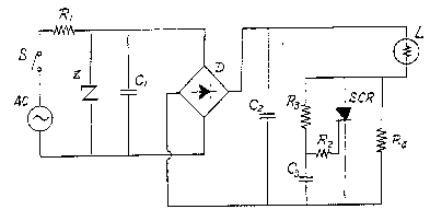
FIG.l is the basic circuit used in the apparatus
according to the invention;
FIG.2 is the curve of a surge current that flows
through lamp filament;
FIG.3 is the curve of an arc discharge current which
may arise in incandescent lamp on filament snapping; and
FIG.4 is a circuit wherein each diode rectlfier is
equipped with a protection circuit against pulse voltage.
Throughout the accompanying drawings, symbol C desig-
nates capacitance; D, diode; L, incandescent lamp; R, resistance;
Z, voltage regulator diode; AC, ac power source; and SCR, re-
verse-blocking ~riode thyristor.
In the circui~ as shown in FIG.l, ac power source AC
energizes voltage regulator diode Z, capacitance Cl (used to
absorb pulse voltage), and diode rectifier D through low resis-
tance Rl which is used to limit the surge current into smoothing
capacitance. The output voltage of diode D is smoothed into dc
by high capacitancé C2. Voltage regulator diode Z absorbs
abnormal voltages which may occur in the power circuit, while
capacitance Cl absorbs high pulse voltages to protect diode
rectifier D. The voltage at capacitance C2 is applied between
incandescent lamp L and resistance R4 which is connected in
series to incandescent lamp L to limit the surge current across
the lamp filament.
~..... .. - .

~g-~
Since the resistance of lamp filament is generally
about 10 ohms when the lamp filament is cold, energization of dc
130 volts to the filament effects an surge current of up to 13
amperes which may snap the filament. Supposing that resistance
R4 is set to 100 ohms, the combined resistance becomes 110 ohms
(= 100 ohms + 10 ohms). Energization of dc 130 volts to the
combined resistance flows an initial filament current of only 1.2
amperes. Thusj the lamp filament is heated without fear of
snapping.
C The voltage ~ resistance R4 simultaneously
energizes reverse-blocking triode thyristor SCR, resistance R3
and capacitance C3. Resistance R2 supplies a triggering voltage
to the gate of reverse-blocking triode thyristor SCR in accor-
dance with the time constant as determined by resistance R3 and
capacitance C3. Triggered thyristor SCR shorts resistance R4,
and the full output voltage of capacitance C2 is, therefore,
supplied to inc~ndescent lamp L. Incandescent lamp L is illumi-
nated with dc in this way.
The surge current across lamp filament is as shown in
FIG.2: When power switch is closed at time to~ the initial
filament current reaches up to 13 amperes as shown with the
broken line because the filament resistance is still relatively
low. The initial filament current can be suppressed to a safe
level of 1.2 amperes by insertion of resistance R4 (100 ohms).
Although the arc discharge current in incandescent lamp
L may reach 200 amperes instantly on filament snapping, insertion

of resistance Rl (2 ohms) suppresses the discharge current to 50
amperes (= 100 volts/2 ohms). Thus, usually-available diodes and
thyristors with permissible peak current of 50 amperes can be
used without precaution of destruction.
Furthermore, the voltage drop at resistance Rl auto-
matically stops the arc to prevent the discharge current result-
ing from the arc. After stopping the arc never restores even
when power switch is closed because the lamp filament would be
sufficiently damaged. If the arc restores, it widens the spark
gap at the filament, followed by stopping by resistance Rl.
Thus, the arc is stopped within a brief time.
Since the apparatus according to the invention instant-
ly and automatically limits arc discharge current in this way,
the circuits parts such as thyristor and diodes are prevented
from damage or destruction.
The arc discharge current is as shown in FIG.3: The
broken line is that of conventionai case; and the solid line is
that of the case in which the apparatus according to the inven-
tion is used.
FIG.4 illustrates a circuit for protecting diode
rectifiers from high pulse voltages which may occur in the power
circuit, wherein capacitances C4, C5, C6 and C7 are connected in
parallel respectively to diodes Dl, D2, D3 and D4 to absorb the
pulse voltages.
- As described above, the apparatus according to the
invention extremely prolongs lamp life because the apparatus
,.,, ., , .~. . ~ ,,
,

--6--
9~
effectively limits a surge current that arises on turning-on of
power switch.
Furthermore, the apparatus according to the invention
prevents a vain destruction of expensive circuit parts other than
incandescent lamp, such as diode, thyristor, distribution line
and fuse because the apparatus instantly and automa~ically limits
arc discharge current.
In addition, since the apparatus is simple, but very
effective in limitation of surge currents, the apparatus can be
advantageously used in illumination apparatuses wherein incan-
descent lamp is illuminated with dc to provide an il].umination of
high brightness, as well as in illumination apparatuses such as
those for vehicles, microscope and photograph.
While I have shown and described particular embodiments
of my invention, it wlll be obvious to those skilled in the art
that various changes and modifica~ions may be made without
departing from my invention in its broader aspects and I, there-
fore, intend in the appended claims to cover all such changes and
modifications as fall within the true spirit and scope of my
invention.

Representative Drawing
A single figure which represents the drawing illustrating the invention.
Administrative Status

2024-08-01:As part of the Next Generation Patents (NGP) transition, the Canadian Patents Database (CPD) now contains a more detailed Event History, which replicates the Event Log of our new back-office solution.

Please note that "Inactive:" events refers to events no longer in use in our new back-office solution.

For a clearer understanding of the status of the application/patent presented on this page, the site Disclaimer , as well as the definitions for Patent , Event History , Maintenance Fee  and Payment History  should be consulted.

Event History

Description Date
Inactive: IPC removed 2021-05-26
Inactive: IPC expired 2020-01-01
Inactive: IPC removed 2019-12-31
Inactive: IPC from MCD 2006-03-11
Time Limit for Reversal Expired 2005-03-03
Letter Sent 2004-03-03
Inactive: Entity size changed 2002-01-21
Grant by Issuance 1992-03-03

Abandonment History

There is no abandonment history.

Fee History

Fee Type Anniversary Year Due Date Paid Date
MF (category 1, 6th anniv.) - small 1998-03-03 1998-02-05
Reversal of deemed expiry 2001-03-05 1998-02-05
MF (category 1, 7th anniv.) - small 1999-03-03 1999-02-08
Reversal of deemed expiry 2001-03-05 1999-02-08
Reversal of deemed expiry 2001-03-05 1999-12-16
MF (category 1, 8th anniv.) - small 2000-03-03 1999-12-16
MF (category 1, 9th anniv.) - small 2001-03-05 2000-12-05
Reversal of deemed expiry 2001-03-05 2000-12-05
MF (category 1, 10th anniv.) - standard 2002-03-04 2002-01-08
MF (category 1, 11th anniv.) - standard 2003-03-03 2003-01-16
Owners on Record

Note: Records showing the ownership history in alphabetical order.

Current Owners on Record
KEN HAYASHIBARA
Past Owners on Record
KAZUMI MASAKI
Past Owners that do not appear in the "Owners on Record" listing will appear in other documentation within the application.
Documents

To view selected files, please enter reCAPTCHA code :


To view images, click a link in the Document Description column. To download the documents, select one or more checkboxes in the first column and then click the "Download Selected in PDF format (Zip Archive)" or the "Download Selected as Single PDF" button.

List of published and non-published patent-specific documents on the CPD .

If you have any difficulty accessing content, you can call the Client Service Centre at 1-866-997-1936 or send them an e-mail at CIPO Client Service Centre.


Document
Description 
Date
(yyyy-mm-dd) 
Number of pages   Size of Image (KB) 
Cover Page 1993-10-27 1 14
Claims 1993-10-27 1 41
Abstract 1993-10-27 1 26
Drawings 1993-10-27 2 28
Descriptions 1993-10-27 6 204
Representative drawing 2001-02-20 1 7
Maintenance Fee Notice 2004-04-28 1 173
Fees 1997-02-20 1 46
Fees 1994-09-01 1 41
Fees 1995-02-28 1 53
Fees 1996-02-22 1 45