Note: Descriptions are shown in the official language in which they were submitted.
9~i8~
The present invention relates to building structures
and to rnethods of constructing them.
In one particular construction technique known as
"pièce en pièce", the area extending between two support columns
is spanned by logs stacked vertically on their sides. The
tenoned ends of each plank are received within mortices formed
in the opposing surfaces of adjacent suppoet columns. Logs of
required length are positioned between the columns by sliding
the logs downwardly so that a lower edge of a first log abuts
the sill timber and subsequent logs stack edgewise on the first
log, giving the characteristic pièce en pièce appearance in
which the columns are exposed.
While this techni~ue results in a building having a
traditional and pleasant appearance, it has certain drawbacks.
It is labour intensive, re~uiring custom-cut logs and a good
de~l of time and effort to assemble the logs in the desired
array. In addition, efforts to complete construction in a
specified time can be stalled when it comes to seal the
structure against weather. There is a tendency for the logs to
slip after positioning and for shrinkage to occur naturally.
Thus, until the logs have settled, the plank/column interface
cannot be caulked effectively, while the interior partitions,
cupboa~ds,~panels and the like cannot be rigidly attached to the
structure.
It is accordingly an object of the present invention to
~k
5~
obviate or mitigate these disadvantages, by providing a novel
building structure and technique for constructing the same.
Briefly stated, there present invention involves a
building comprising:
a structural framework including adjacent support
columns, each of the support colu~ns being joined at one end to
a sill beam and at another end to a plate beam, each pair of the
adjacent support columns and the sill and plate beams
therebetwean having opposed faces defining a region therebetween;
and
a building module arranged to fit snugly in the region,
the module comprising a panel having a weather barrier and an
outer surface which is representati~e of stacked logs, the
support columns and beams being thicker than the module so that,
when the module is assembled between the opposed faces, the
support columns extend beyond the module on the interior and
exterior sides thereof and remain exposed in such a manner that
the exposed support columns and the outer surface together
simulate a piece en piece building appearance.
In another aspect of the present in~ention, there is
provided a method of erecting a wall area with a piece en piece
appearance, the method including the steps of:
providing a structural framework including a pair of
support columns, each of the support columns being joined at one
end to a sill beam and at another end to a plate beam;
providing the adjacent support columns and the sill and
plate beams with opposed faces to define a region therebetween,
providing a building module to fit in the region;
providing the module with a weather barrier and with
a panel having an outer surface which is representative of
stacked logs; and
arranging the support columns and the beams so that
they are thicker than the module so that, when the module is
assembled between the opposed faces, the support columns extend
beyond the module on the interior and exterior sides thereof and
5~
remain exposed in such a manner that the exposed support columns
and the outer surface together simulate the piece en piece
building appearance.
The ~odules of the present invention offer the
advantage that they may be preassembled and brought to the site
as and when required. This reduces the time required on site to
complete the construction, contributing to cost ~ffectiveness.
Where the panel is represented by vertically stacked planks in
the piece en piece fashion, additional, specific advantages are
realized. Whereas slippage and shri~kage is otherwise normally
,
9~85'7
encountered, the module of the present invention allows only
mini~al slippage and shrinkage since each plank is rigidly
connected between the two uprights and each upright is, in turn,
riyidly connected to a support column. Sealing around the
module can thus be performed without undue delay i.e. without
waiting for settling of the planks, which would otherwise be
necessary.
Once the uprights and panel are attached and caulked,
the area behind the panel may be insulated and covered using any
desired cladding. The cladding is most preferably attached to
the module through the uprights although it may be attached to
the columns, if desired.
A third aspect of the present invention resides in the
building erected using the modules. These buildings are as
pleasing in appearance and quality as those constructed by the
previously described, known methods yet they are more cost
attractive.
Embodiments of the invention are hereinafter described
by way of example only with reference to the accompanying
drawings in which:
Pigure l represents a perspective view of a building
partially ~onstructed USiAg building modules.
.
.
,.. . .
Figure 2 represents an exploded view of a module; and
Figure 3 represents a sectional view taken on line 3-3
of Figure 1.
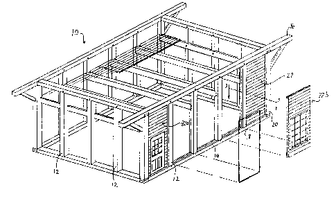
The structural framework 10 of a building is shown in
Figure 1. The frame work includes a plurality of support column5
12 extending between sill beams 14, and plate beams 16. E~ of
the sill and plate beams 14, 16 and the support columns lB and
has an inner surface that is planar across its entir~ width
This allows the module to slide laterally into place from either
the interior or exterior sides of the building. In the area
between adjacent support columns 18 and 20 is a module 22 which
extends between the floor and sill and plate beams 14 and 16.
Module 22 is shown in isolation in Figure 2. The
module has four side faces each of which is planar across its
entire width and a framework 24 formed from 2" X 4" studs,
including uprights 26, 28, top member 30 and bottom member 32.
Cross-members 34 are incorporated for stability. To the
framework is connected a panel 36 having an inner sheet of
material 38 acting as a weather barrier and an outer array of
planks 40 which reproduce the piece en piece appearance. The
area defined by the framework 24 is Eilled with insulating
material 42. Attached to this inner surface of the framework 24
is a vapour barrier sheet 43 to which is connected a layer of
interior cladding 44. Cladding 44 is presented to the interior
of the dwelling and may be painted or embellished in any manner
desired by the dweller of the completed building.
.. ... ~,,
, .. .
15'7
In order for the module to be accommodated between adjacent support
columns, the marginal edges of the module are defined by the framework 24 as shown in
Figure 3. In the embodiment depicted in Figure 3, the marginal edges of the panel 36 are
coextensive with the perimeter of the framework, as well.
In addition, the inner and outer peripheries of ~he support columns 18, 20
extend beyond the peripheries of the int~rior cladding 44 and the planks 40 so as ~o
accentuate the piéce en pi~ce appearance.
.
In order to form the module, each of the panel 36, cladding 44 and
framework 24 may be cut or formed independently to desired specifications and connected
to the framework. Alternatively, the framework may first be formed and used as a guide
to trim the panel, once connected. This latter technique may be useful particularly when
the planks form the exterior surface of the module to ensure that there is no plank
overhanging the framework. In this way, the module can be accommodated snugly
between opposed faces of two adjacent columns by abutment between the columns and the
framework.
To connect the module in position, nails 43 are hammered through the
framework into the columns and into the sill and plate beams when the module extends
thereto. To allow for this nailing, it will be appreciated that the
i . .
,, - . .
~2~35'7
-- 7 --
insulating material and internal cladding are absent and are
added only once the module is securely connected. Because the
framework depends from the panel, ample room is provided within
the confines of the module for the swinging of a hammer to
effect the nailing. As an alternative, the framework may be
connected first and the panel then nailed to the framework to
allow more freedom for nailing. However, prior connection of
the panel to the framework is greatly preferred, thereby to
reduce the construction time required on site.
After the framework and panel are secured, the
framework/column interface may be sealed by the use of caulking
foam or other suitable material, almost instantaneously since it
is so rigidly positioned and slippage and shrinkage are almost
negligible. After sealing, insulation is added and the interior
cladding is connected. Interior cladding may be connected
directly to the framework, as shown in Figure 3 or connected to
the support columns, if desired.
In wall areas where windows and/or doors are to be
positioned, the modules such as those identified as 22a and 22b
in Flgure 1 are designed to accommodate them on a sub-frame
attached to the panel and connected with the framework for
stability. Despite the existence of the sub-frame, adequate
space is provided for the nailing action required to fix the
module in position.
, ,,.,
'
~?~68s7
To accelerate the construction process, the support columns may be spaced
at constant distances so that a number of modules of the same siæ can be prefabricated
for future use. There may, however, be two or more distances which are selected to be
constant so that two or more panel sizes may be required. Sevcral variations of the
framework 10 are contemplated including the p.rovision of rigid insulation in place of the
weather barrier 38.
~ ~'`1
~....~` !-',.