Language selection

Search

Patent 1296972 Summary

Third-party information liability

Some of the information on this Web page has been provided by external sources. The Government of Canada is not responsible for the accuracy, reliability or currency of the information supplied by external sources. Users wishing to rely upon this information should consult directly with the source of the information. Content provided by external sources is not subject to official languages, privacy and accessibility requirements.

Claims and Abstract availability

Any discrepancies in the text and image of the Claims and Abstract are due to differing posting times. Text of the Claims and Abstract are posted:

  • At the time the application is open to public inspection;
  • At the time of issue of the patent (grant).
(12) Patent: (11) CA 1296972
(21) Application Number: 1296972
(54) English Title: MOTOR-DRIVEN CHAIN SAW
(54) French Title: SCIE A CHAINE MOTORISEE
Status: Expired and beyond the Period of Reversal
Bibliographic Data
(51) International Patent Classification (IPC):
  • B27B 17/02 (2006.01)
  • B27B 17/08 (2006.01)
  • B27B 33/14 (2006.01)
(72) Inventors :
  • FISCHER, MANFRED (Germany)
  • DUSSLER, KLAUS (Germany)
  • LINKE, WILFRIED (Germany)
  • HARTMANN, WERNER (Germany)
(73) Owners :
  • FIRMA ANDREAS STIHL
(71) Applicants :
  • FIRMA ANDREAS STIHL (Germany)
(74) Agent: SMART & BIGGAR LP
(74) Associate agent:
(45) Issued: 1992-03-10
(22) Filed Date: 1987-11-25
Availability of licence: N/A
Dedicated to the Public: N/A
(25) Language of filing: English

Patent Cooperation Treaty (PCT): No

(30) Application Priority Data:
Application No. Country/Territory Date
P 36 40 846.8 (Germany) 1986-11-29

Abstracts

English Abstract


Abstract of the Disclosure
For motor-driven chain saws, there is the danger that the
chain saw will be kicked back if the reaction forces suddenly
increase intensely in response to the forward thrust. This
kickback effect and the danger of accident associated
therewith are intended to be prevented by means of a special
configuration of the saw chain. The saw chain has drive links
which have an approximately triangular shape and which engage
the tooth gaps of the nose sprocket with inclined flanks. The
drive links are configured to be asymmetrical with respect to
a partition line running between the two pivot axes of the
link so that the forward flank angle is greater than the
rearward flank angle referred to the partition line. The two
flank angles together are greater than the opening angle of
the V-shaped tooth gap of the nose sprocket. The saw chain
can be configured as a low-profile chain with the spacing
between the pivot axes of the cutting link being at least 10
greater than the spacing of the cutting edge to the plane
containing the connecting line between the two pivot axes of
the cutting link. Furthermore, the depth limiter can have an
area in its upper region which is at least 4 mm2.


Claims

Note: Claims are shown in the official language in which they were submitted.


232968-333
THE EMBODIMENTS OF THE INVENTION IN WHICH AN EXCLUSIVE
PROPERTY OR PRIVILEGE IS CLAIMED ARE DEFINED AS FOLLOWS:
1. A guide bar and saw chain assembly for a motor-driven
chain saw, the assembly comprising:
a guide bar having upper and lower edges and a nose
sprocket mounted in the forward end thereof;
said nose sprocket having a plurality of teeth and each
two mutually adjacent ones of said teeth conjointly defining a V-
shaped tooth gap having an opening angle;
one of said two mutually adjacent teeth being a forward
tooth when viewed in the direction of the movement of said saw
chain and the other one of said teeth being a rearward tooth, said
rearward tooth having a forward flank and said forward tooth
having a rearward flank;
a plurality of links pivotally interconnected by rivet
pins or the like to form an endless saw chain guided on said guide
bar on said edges and on said nose sprocket;
a first portion of said links being cutting links and a
second portion of said links being drive links;
each one of said cutting links including: a plate-like
cutting-link body having an upwardly extending rearward portion
defining a cutting tooth; and, a forward upwardly extending
portion defining a depth limiter;
each one of said drive links being a triangularly-shaped
plate-like body having a forward bore and a rearward bore formed
therein for accommodating two of said pins to define respective
16

232968-333
pivot axes;
each of said drive links having two downwardly extending
inclined flanks for engaging said tooth gaps and said two
downwardly extending inclined flanks having respective contours
which extend asymmetrically with respect to a partition line drawn
approximately perpendicularly to and approximately bisecting a
connecting line passing through said pivot axes;
one of said inclined flanks being a forward flank which
defines a forward flank angle (VFW) with said partition line and
is in contact engagement with said forward flank of said rearward
tooth; the other one of said inclined flanks being a rearward
flank which defines a rearward flank angle (HFW) with said
partition line and is in contact engagement with said rearward
flank of said forward tooth; and, said forward flank angle (VFW)
being greater than said rearward flank angle (HFW); and,
said forward flank angle and said rearward flank angle
conjointly defining an angle greater than said opening angle.
2. A guide bar and saw chain assembly for a motor-driven
chain saw, the assembly comprising:
a guide bar having upper and lower edges and a nose
sprocket mounted in the forward end thereof;
said nose sprocket having a plurality of teeth and each
two mutually adjacent ones of said teeth conjointly defining a V-
shaped tooth gap having an opening angle;
a plurality of links pivotally interconnected by rivet
pins or the like to form an endless saw chain guided on said guide
17

232968-333
bar on said edges and on said nose sprocket;
a first portion of said links being cutting links and a
second portion of said links being drive links;
each one of said cutting links including: a plate-like
cutting-link body having an upwardly extending rearward portion
defining a cutting tooth; and, a forward upwardly extending
portion defining a depth limiter;
each one of said drive links being a triangularly-shaped
plate-like body having a forward bore and a rearward bore formed
therein for accommodating two of said pins to define respective
pivot axes;
each of said drive links having two downwardly extending
inclined flanks for engaging said tooth gaps and said drive-link
body being asymmetrical with respect to a partition line drawn
approximately perpendicularly to a connecting line passing through
said pivot axes;
one of said flanks being a forward flank which defines a
forward flank angle (VFW) with said partition line; the other one
of said flanks being a rearward flank which defines a rearward
flank angle (HFW) with said partition line; and, said forward
flank angle (VFW) being greater than said rearward flank angle
(HFW);
said forward flank angle and said rearward flank angle
conjointly defining an angle greater than said opening angle; and,
said saw chain is a low-profile saw chain and wherein
each of said plate-like cutting-link bodies having a forward bore
opening for accommodating one of said rivets therein and a
18

232968-333
rearward bore opening for accommodating another one of said rivets
therein, said forward and rearward bore openings defining
respective bore centers located at a predetermined bore spacing
from each other; and, said bore spacing being equal to or greater
than 1.1 times the elevation measured from a line connecting said
bore centers to said cutting tooth.
3. The guide bar and saw chain assembly of claim 2, said
depth limiter of said cutting link having an upper surface having
an area of at least 4 mm2.
4. The guide bar and saw chain assembly of claim 1, each of
the two mutually adjacent teeth of said nose sprocket having
mutually adjacent tooth flanks conjointly defining said V-shaped
tooth gap, said tooth flanks being configured so as to cause said
tooth gap to be without undercuts.
5. The guide bar and saw chain assembly of claim 1, said
forward flank angle (VFW) being approximately 1.1 to 1.4 times
greater than said rearward flank angle HFW.
6. A guide bar and saw chain assembly for a motor-driven
chain saw, the assembly comprising:
a guide bar having upper and lower edges and a nose
sprocket mounted in the forward end thereof;
said nose sprocket having a plurality of teeth and each
two mutually adjacent ones of said teeth conjointly defining a V-
19

232968-333
shaped tooth gap having an opening angle
a plurality of links pivotally interconnected by rivet
pins or the like to form an endless saw chain guided on said guide
bar on said edges and on said nose sprocket;
a first portion of said links being cutting links and a
second portion of said links being drive links;
each one of said cutting links including: a plate-like
cutting-link body having an upwardly extending rearward portion
defining a cutting tooth; and, a forward upwardly extending
portion defining a depth limiter;
each one of said drive links being a triangularly-shaped
plate-like body having a forward bore and a rearward bore formed
therein for accommodating two of said pins to define respective
pivot axes;
each of said drive links having two downwardly extending
inclined flanks for engaging said tooth gaps and said drive-link
body being asymmetrical with respect to a partition line drawn
approximately perpendicularly to a connecting line passing through
said pivot axes;
one of said flanks being a forward flank which defines a
forward flank angle (VFW) with said partition line; the other one
of said flanks being a rearward flank which defines a rearward
flank angle (HFW) with said partition line; and, said forward
flank angle (VFW) being greater than said rearward flank angle
(HFW);
said forward flank angle and said rearward flank angle
conjointly defining an angle greater than said opening angle; and,

232968-333
said forward flank angle (VFW) being approximately 1.25
times greater than said rearward flank angle HFW.
7. A guide bar and saw chain assembly for a motor-driven
chain saw, the assembly comprising:
a guide bar having upper and lower edges and a nose
sprocket mounted in the forward end thereof;
said nose sprocket having a plurality of teeth and each
two mutually adjacent ones of said teeth conjointly defining a V-
shaped tooth gap having an opening angle;
a plurality of links pivotally interconnected by rivet
pins or the like to form an endless saw chain guided on said guide
bar on said edges and on said nose sprocket;
a first portion of said links being cutting links and a
second portion of said links being drive links;
each one of said cutting links including: a plate-like
cutting-link body having an upwardly extending rearward portion
defining a cutting tooth; and, a forward upwardly extending
portion defining a depth limiter;
each one of said drive links being a triangularly-shaped
plate-like body having a forward bore and a rearward bore formed
therein for accommodating two of said pins to define respective
pivot axes;
each of said drive links having two downwardly extending
inclined flanks for engaging said tooth gaps and said drive-link
body being asymmetrical with respect to a partition line drawn
approximately perpendicularly to a connecting line passing through
21

232968-333
said pivot axes;
one of said flanks being a forward flank which defines a
forward flank angle (VFW) with said partition line; the other one
of said flanks being a rearward flank which defines a rearward
flank angle (HFW) with said partition line; and, said forward
flank angle (VFW) being greater than said rearward flank angle
(HEW);
said forward flank angle and said rearward flank angle
conjointly defining an angle greater than said opening angle; and,
said rearward flank angle (HFW) being equal to half of
said opening angle of said tooth gap.
8. A guide bar and saw chain assembly for a motor-driven
chain saw, the assembly comprising:
a guide bar having upper and lower edges and a nose
sprocket mounted in the forward end thereof;
said nose sprocket having a plurality of teeth and each
two mutually adjacent ones of said teeth conjointly defining a V-
shaped tooth gap having an opening angle;
a plurality of links pivotally interconnected by rivet
pins or the like to form an endless saw chain guided on said guide
bar on said edges and on said nose sprocket;
a first portion of said links being cutting links and a
second portion of said links being drive links;
each one of said cutting links including: a plate-like
cutting-link body having an upwardly extending rearward portion
defining a cutting tooth; and, a forward upwardly extending
22

232968-333
portion defining a depth limiter;
each one of said drive links being a triangularly-shaped
plate like body having a forward bore and a rearward bore formed
therein for accommodating two of said pins to define respective
pivot axes;
each of said drive links having two downwardly extending
inclined flanks for engaging said tooth gaps and said drive-link
body being asymmetrical with respect to a partition line drawn
approximately perpendicularly to a connecting line passing through
said pivot axes;
one of said flanks being a forward flank which defines a
forward flank angle (VFW) with said partition line; the other one
of said flanks being a rearward flank which defines a rearward
flank angle (HFW) with said partition line; and, said forward
flank angle (VFW) being greater than said rearward flank angle
(HFW);
said forward flank angle and said rearward flank angle
conjointly defining an angle greater than said opening angle; and,
said rearward flank angle (HFW) being approximately 40°;
said forward flank angle (VFW) being approximately 50°; and, said
opening angle of said tooth gap being approximately 80°.
9. A guide bar and saw chain assembly for a motor-driven
chain saw, the assembly comprising:
a guide bar having upper and lower edges and a nose
sprocket mounted in the forward end thereof;
said nose sprocket having a plurality of teeth and each
23

232968-333
two mutually adjacent ones of said teeth conjointly defining a V-
shaped tooth gap having an opening angle;
a plurality of links pivotally interconnected by rivet
pins or the like to form an endless saw chain guided on said guide
bar on said edges and on said nose sprocket;
a first portion of said links being cutting links and a
second portion of said links being drive links;
each one of said cutting links including: a plate-like
cutting-link body having an upwardly extending rearward portion
defining a cutting tooth; and, a forward upwardly extending
portion defining a depth limiter;
each one of said drive links being a triangularly-shaped
plate-like body having a forward bore and a rearward bore formed
therein for accommodating two of said pins to define respective
pivot axes;
each of said drive links having two downwardly extending
inclined flanks for engaging said tooth gaps and said drive-link
body being asymmetrical with respect to a partition line drawn
approximately perpendicularly to a connecting line passing through
said pivot axes;
one of said flanks being a forward flank which defines a
forward flank angle (VFW) with said partition line; the other one
of said flanks being a rearward flank which defines a rearward
flank angle (HFW) with said partition line; and, said forward
flank angle (VFW) being greater than said rearward flank angle
(HFW);
said forward flank angle and said rearward flank angle
24

232968-333
conjointly defining an angle greater than said opening angle; and,
one of said two mutually adjacent teeth being a forward
tooth when viewed in the direction of the movement of said saw
chain and the other one of said teeth being a rearward tooth, the
tips of said teeth defining a tooth circle; said forward flank
angle (VFW), said rearward flank angle (HFW) and said opening
angle all being configured so as to cause said rearward flank of
said drive link to be in flush surface contact engagement with
said forward flank of said rearward tooth when no external load is
applied to said saw chain and so as to cause said forward flank of
said drive link and said rearward flank of said forward tooth to
conjointly define an angularly-shaped free space therebetween also
in the absence of said external load, said forward flank of said
drive link being in point contact engagement with said forward
tooth at the upper region thereof near said tooth circle.
10. A guide bar and saw chain assembly for a motor-driven
chain saw, the assembly comprising:
a guide bar having upper and lower edges and a nose
sprocket mounted in the forward end thereof;
said nose sprocket having a plurality of teeth and each
two mutually adjacent ones of said teeth conjointly defining a V-
shaped tooth gap having an opening angle;
a plurality of links pivotally interconnected by rivet
pins or the like to form an endless saw chain guided on said guide
bar on said edges and on said nose sprocket;
a first portion of said links being cutting links and a

232968-333
second portion of said links being drive links;
each one of said cutting links including: a plate-like
cutting-link body having an upwardly extending rearward portion
defining a cutting tooth; and, a forward upwardly extending
portion defining a depth limiter;
each one of. said drive links being a triangularly-shaped
plate-like body having a forward bore and a rearward bore formed
therein for accommodating two of said pins to define respective
pivot axes;
each of said drive links having two downwardly extending
inclined flanks for engaging said tooth gaps and said drive-link
body being asymmetrical with respect to a partition line drawn
approximately perpendicularly to a connecting line passing through
said pivot axes;
one of said flanks being a forward flank which defines a
forward flank angle (VFW) with said partition line; the other one
of said flanks being a rearward flank which defines a rearward
flank angle (HFW) with said partition line; and, said forward
flank angle (VFW) being greater than said rearward flank angle
(HFW);
said forward flank angle and said rearward flank angle
conjointly defining an angle greater than said opening angle; and,
one of said two mutually adjacent teeth being a forward
tooth when viewed in the direction of the movement of said saw
chain and the other one of said teeth being a rearward tooth, the
tips of said teeth defining a tooth circle; said forward flank
angle (VFW), said rearward flank angle (HFW) and said opening
26

232968-333
angle all being configured so as to cause the forward flank of
said rearward tooth and said rearward flank of drive link to
conjointly define an angularly-shaped free space therebetween with
said rearward flank of said drive link being in point contact
engagement with said rearward tooth in the upper region thereof
near said tooth circle in response to an external load being
applied to said saw chain and so as to cause said forward flank of
said drive link to be in flush surface contact engagement with the
rearward tooth flank of said forward tooth also in response to
said load.
11. The guide bar and saw chain assembly of claim 2, wherein
said tooth gap has a tooth foot and said cutting tooth has a
cutting edge which traces a cutting edge circle as it moves with
said nose sprocket around the forward end of said guide bar; said
rearward bore lying in said rearward flank angle (HFW) and said
forward bore lying in said forward flank angle (VFW); the distance
from said tooth foot to the pivot axis corresponding to said
rearward bore being less than the distance from said tooth foot to
the pivot axis corresponding to said forward bore; the cutting
links being pivotally connected directly to and behind selected
ones of said driving links; each one of said cutting links being
pivotally connected at its forward bore opening to the drive link
corresponding thereto at the rearward bore of the latter; said
forward flank angle (VFW), said rearward flank angle (HFW) and
said opening angle all being configured so as to cause the rear of
said cutting tooth to be in the immediate vicinity of or to
27

232968-333
project beyond said cutting edge circle in response to a load
applied to the saw chain as it moves with said nose sprocket
around the forward end of said guide bar.
12. A guide bar and saw chain assembly for a motor-driven
chain saw, the assembly comprising:
a guide bar having upper and lower edges and a nose
sprocket mounted in the forward end thereof;
said nose sprocket having a plurality of teeth and each
two mutually adjacent ones of said teeth conjointly defining a V-
shaped tooth gap having an opening angle;
a plurality of links pivotally interconnected by rivet
pins or the like to form an endless saw chain guided on said guide
bar on said edges and on said nose sprocket;
a first portion of said links being cutting links and a
second portion of said links being drive links;
each one of said cutting links including: a plate-like
cutting-link body having an upwardly extending rearward portion
defining a cutting tooth; and, a forward upwardly extending
portion defining a depth limiter;
each one of said drive links being a triangularly-shaped
plate-like body having a forward bore and a rearward bore formed
therein for accommodating two of said pins to define respective
pivot axes;
each of said drive links having two downwardly extending
inclined flanks for engaging said tooth gaps and said drive-link
body being asymmetrical with respect to a partition line drawn
28

232958-333
approximately perpendicularly to a connecting line passing through
said pivot axes;
one of said flanks being a forward flank which defines a
forward flank angle (VFW) with said partition line; the other one
of said flanks being a rearward flank which defines a rearward
flank angle (HFW) with said partition line; and, said forward
flank angle (VFW) being greater than said rearward flank angle
(HFW);
said forward flank angle and said rearward flank angle
conjointly defining an angle greater than said opening angle; and,
a rearward portion of said connecting line extends
toward the pivot axis corresponding to said rearward bore, said
rearward portion of said connecting line and said partition line
conjointly defining a first angle; and, wherein a forward portion
of said connecting line extends toward the pivot axis
corresponding to said forward bore, said forward portion of said
connecting line and said partition line conjointly defining a
second angle; said forward and rearward bores of said drive link
are formed in said triangularly-shaped plate-like body so as to
cause said axes to be displaced with respect to said partition
line so as to cause said first angle to be greater than 90° and so
as to cause said second angle to be less than 90°.
13. A guide bar and saw chain assembly for a motor-driven
chain saw, the assembly comprising:
a guide bar having upper and lower edges and a nose
sprocket mounted in the forward end thereof;
29

232968-333
said nose sprocket having a plurality of teeth and each
two mutually adjacent ones of said teeth conjointly defining a V-
shaped tooth gap having an opening angle;
a plurality of links pivotally interconnected by rivet
pins or the like to form an endless saw chain guided on said guide
bar on said edges and on said nose sprocket;
a first portion of said links being cutting links and a
second portion of said links being drive links;
each one of said cutting links including: a plate-like
cutting-link body having an upwardly extending rearward portion
defining a cutting tooth; and, a forward upwardly extending
portion defining a depth limiter;
each one of said drive links being a triangularly-shaped
plate-like body having a forward bore and a rearward bore formed
therein for accommodating two of said pins to define respective
pivot axes;
each of said drive links having two downwardly extending
inclined flanks for engaging said tooth gaps and said drive-link
body being asymmetrical with respect to a partition line drawn
approximately perpendicularly to a connecting line passing through
said pivot axes;
one of said flanks being a forward flank which defines a
forward flank angle (VFW) with said partition line; the other one
of said flanks being a rearward flank which defines a rearward
flank angle (HFW) with said partition line; and, said forward
flank angle (VFW) being greater than said rearward flank angle
(HFW);

232968-333
said forward flank angle and said rearward flank angle
conjointly defining an angle greater than said opening angle; and,
said rearward flank of said drive link being subdivided
into an upper flank segment and a lower flank segment; said lower
flank segment and said partition line conjointly defining said
rearward flank angle (HFW); and, said upper flank segment and said
partition line conjointly defining an upper flank angle (OFW) and
said upper segment having a slope so as to cause said upper flank
angle (OFW) to be less than said rearward flank angle (HFW).
14. The guide bar and saw chain assembly of claim 13, said
upper flank angle (OFW) and said forward flank angle (VFW)
together being equal to said opening angle.
15. The guide bar and saw chain assembly of claim 14, one of
said two mutually adjacent teeth being a rearward tooth when
viewed in the direction of the movement of the saw chain, said
rearward tooth having a forward flank; said upper flank segment
having a slope selected so as to cause said upper flank segment to
be in flush surface contact engagement with said flank of said
rearward tooth in response to a load applied to said saw chain.
16. A motor-driven chain saw comprising:
a housing;
a guide bar mounted on said housing and having upper and
lower edges and a nose sprocket rotatably mounted in the forward
end thereof;
31

232968-333
one of said two mutually adjacent teeth being a forward
tooth when viewed in the direction of the movement of said saw
chain and the other one of said teeth being a rearward tooth, said
rearward tooth having a forward flank and said forward tooth
having a rearward flank;
said nose sprocket having a plurality of teeth and each
two mutually adjacent ones of said teeth conjointly defining a V-
shaped tooth gap having an opening angle;
a plurality of links pivotally interconnected by rivet
pins or the like to form an endless saw chain guided on said guide
bar on said edges and on said nose sprocket;
a first portion of said links being cutting links and a
second portion of said links being drive links;
each one of said cutting links including: a plate-like
cutting-link body having an upwardly extending rearward portion
defining a cutting tooth; and, a forward upwardly extending
portion defining the depth limiter;
each one of said drive links being a triangularly-shaped
plate-like body having a forward bore and rearward bore formed
therein for accommodating two of said pins to define respective
pivot axes;
each of said drive links having two downwardly extending
inclined flanks for engaging said tooth gaps and said two
downwardly extending inclined flanks having respective contours
which extend asymmetrically with respect to a partition line drawn
approximately perpendicularly to and approximately bisecting a
connecting line passing through said pivot axes;
32

232968-333
one of said inclined flanks being a forward flank which
defines a forward flank angle (VFW) with said partition line and
is in contact engagement with said forward flank of said rearward
tooth; the other one of said inclined flanks being a rearward
flank which defines a rearward flank angle (HFW) with said
partition line and is in contact engagement with said rearward
flank of said forward tooth; and, said forward flank angle (VFW)
being greater than said rearward flank angle (HFW); and,
said forward flank angle and said rearward flank angle
conjointly defining an angle greater than said opening angle.
33

Description

Note: Descriptions are shown in the official language in which they were submitted.


;97'~
Motor-Driven Chain Saw
Field of the Invention
The invention relates to a motor~driven chain saw and a
guide bar and saw chain assembly therefor. The saw chain has
links interconnected to provide an endless chain which runs
along the periphery of the guide bar which has a nose
spEocket. The links of the saw chain include cutting links
each having a cutting tooth and a depth limiter as well as
triangularly-shaped drive links. Each drive link is
interconnected with the rest of the saw chain via two pins
defining respective pivot axes. The drive links have inclined
flanks for engaging tooth gaps of the nose-sprocket defined by
mutually adjacent ones of the teeth thereof.
Background of the Invention
Known portable handheld motor-driven chain saws are
equipped with a guide bar which extends outwardly in the front
thereof and on which a continuous saw chain is journalled for
movement around the periphery thereof. A nose sprocket is
mounted in the front end of the guide bar for changing the
direction of the saw chain as it moves around the guide bar.
The saw chain includes cutting links and triangular-shaped
driving links with the latter engaging tooth gaps disposed
between each two mutually adjacent ones of the teeth of the
nose sprocket. The inclined flanks of the triangularly-shaped
driv~ links are thereby in contact engagement with the
inclined tooth flanks which laterally limit the tooth gaps.
Each of the cutting links includes a cutting tooth and a depth
limiter disposed ahead of the cutting tooth and which limits
the depth to which the cutting tooth can cut into the wood.
When cutting into soft wood and/or when the operator of the

;;97~
232~36~s-~3
chain saw applies a large thrust pressure, the tooth can indeed
cut too deepl~ into the wood 50 that a kickback effect occurs
during plunge cutting operations at the forward nose region of the
guide har. Such a sudden kickback of the chain saw presents a
direct danger to the operator.
Sum~arv of the Invention
The invention provides a quide bar and saw chain
assembly for a motor-driven chain saw, the assembly comprising:
a guide bar having upper and lower edges and a nose sprocket
mounted in the forward end thereof; said nose sprocket having a
plurality of teeth and e~ch two mutually adjacent ones of said
teeth conjointly defining a V-shaped tooth gap having an opening
angle; one of said two mutually adjacent teeth being a forward
tooth when viewed in the direction of the movement of said saw
chain and the other one of said teeth being a rearward tooth, said
rearward tooth havins a forward flank and said forward tooth
having a rearward flank; a plurality of links pivotally
interconnected by rivet pins or the like to form an endless saw
chain guided on said guide bar on said edges and on said nose
sprocket; a first portion of said links being cutting links and a
second portion of said links being drive links; each one of said
cutting links including: a plate-like cutting-link body having an
upwardly extending rearward portion defining a cutting tooth; and,
a forward upwardly extending portion de~ining a depth limiter;
each one of said drive links being a triangularly-shaped plate-
like body having a forward bore and a rearward bore formed therein
for accommodating two of said pins to define respective pivot

,97~
232:~j6~3 333
axes; each of said clrive links having two do~nwardl~ extending
inclined flanks fo~ engaging said tooth gaps and said two
downwardly extending inclined flanks having respective contours
which extend asymmetrically with respect to a partition line drawn
approximately perpendicularly to and approximately hisecting a
connecting line passing through said pivot axes; one of said
inclined flanks being a forward flank which defines a forward
flank angle (VFW) with said partition line and is in contact
engagement with said forward flank of said rearward tooth; the
other one of said inclined flanks being a rearward flank which
defines a rearward flank angle (HFW) with said partition line and
is in contact engagement with said rearward flank of said forward
tooth; and, said forward flank angle (VFW) being greater than said
rearward flank angle (HFW); and, said forward flank angle and said
rearward flank angle conjointly defining an angle greater than
said opening angle.
Brief Description of the Drawinqs
The invention will now be described with reference to
the drawings wherein:
FIG. 1 is a side elevation view of a handheld portable
motor-driven chain saw having a guide bar on which a continuous
saw chain is guided;
EIG. 2 is an enlarged side elevation view of the saw
chain according to a preferred embodiment of the invention;
FIG. 3 is a plan view of the saw chain shown in FIG. 2;
FIG. 4 shows two links of the saw chain as they enter
into contact engagement with the nose sprocket;

~ 3296~-333
FIG. 5 is an enlarged s:ide elevation view of three links
as they appear at ~.he forward end of the nose sprocket with a
thrust force acting from outside against the saw chain as
represented by an arrow;
FIG. 6 is an enlarged side elevation view of a portion
of the saw chain of FIGS. 1 to 3 as it runs out from the nose
sprocket,
FIG. 7 is an enlarged side elevation view of a portion
of
3a
.~

1 ~'3~i~17 ~
the saw chain and the nose sprocket at lts u~per entry onto
the nose sprocket similar to that shown in FIG. 4;
FIG. 8 is an enlarged side elevation view of the saw
chain at its upper entry onto the nose sprocket corresponding
to FIG. 7, however, with a thrust force acting from the
outside against the saw chain;
FIG. 9 is an enlarged side elevation view of the drive
link of the saw chain and a portion of the nose sprocket,
however, with rivet bores displaced in elevation with respect
to one another; and,
FIG. 10 is an enlarged side elevation view of the drive
link of the saw chain and a portion of the nose sprocket
similar to FIG. 9 with an additional incline on the rear flank
of the drive link.
Descri~ion of the_Preferred Embodiments of the Invention
The handheld motor-driven chain saw 1 includes a
housing 2 containing a drive motor 3 which can be configured
as a gasoline engine. The housing includes a rear handle 4
with a gas throttle 5 and a gas-lever latch 6. A bail
~0 handle 7 extends over the top of the housing 2 and a hand
guard 8 is journalled ahead of the handle 7. Furthermore, the
chain saw 1 includes a guide bar 9 extending forwardly of the
housing 2. A continuous saw chain 10 is journalled on the
guide bar 9 for movement about the periphery thereof. The saw
~5 chain 10 is driven by the drive motor 3 in the direction of
the arrow U. A nose sprocket 11 is rotatably journalled at
the forward end of the guide bar 9 for rotation about an axis
and is provided to guide the saw chain 10 about the front end
of the guide bar.
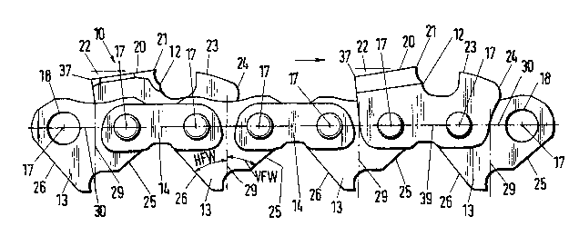
As shown in FIGS. 2 and 3, the saw chain 10 includes

;"3~7~
cutting links 12, drive links 13 and connecting links 14 which
are pivotally interconnected. The t~iangularly-shaped drive
links 13 engage the tooth gaps 16 forrned between the teeth 15
of the nose sprocket 11.
The cutting links 12 as well as the drive links 13 and
connecting links 14 each have forward and rearward pivot
axes 17 viewed in the direction of movement of the saw chain.
Each of the cutting links 12, drive links 13 and connecting
links 14 have two holes 18 formed therein for accommodating
rivet pins 19 by means of which the links (12, 13, 14) are
pivotally interconnected. FIGS. 2 and 3 show that the spacing
between the forward pivot axis 17 and the rearward pivot
axis 17 is larger for the cutting link 12 and connecting
link 14 than for the drive link 13. The cutting links 12 and
the connecting links 14 of this embodiment are configured as
side links; whereas, the drive links 13 are so-called middle
links which are iournalled between two connecting links 14 or
between a cutting link 12 and a connecting link 14.
The cutting link 12 has a saw tooth 20 at its rearward
upper portion. The saw tooth 20 is kent over transversely to
the plane of the plate-like body of the cutting link and has a
forward cutting edge 21. The saw tooth 20 is inclined
rearwardly starting at the cutting edge 21 so that a free
angle 2? is formed. The magnitude of the free angle 20 can be
approximately 6 to 8 in order to provide a high cutting
capacity and nonetheless substantially eliminate the kickback
effect. The preferred magnitude of the free angle 20 can be
approximately 7.
A depth limiter 23 is formed at the forward portion of
the cutting link 12. The depth limiter 23 is somewhat bent

'1 "!~;'37:~
over with respect to the plane of the plate-like body of the
cutting link. The depth limiter 23 is disposed and spaced
ahead of the cutting tooth 20 and is so configured that the
rounded forward edge 24 extends to beyond and over the middle
region of the drive link 13 in the direction toward the
forward pivot axis 17.
The saw chain 10 of the above-described embodiment is
configured as a so-called low-profile chain. That is, the
spacing between the forward and rearward pivot axes 17 of the
cutting link 12 along the connecting axis 39 is larger than
the tooth height. For the cutting tooth 20, the tooth height
is determined by the spacing of the cutting edge 21 to the
connecting axis 39. The tooth roof of the cutting edge 21 is
where the cutting and reaction forces act. The tooth roof
also has a free angle transverse to the direction of movement
of the saw chain so that the cutting edge 21 is not at the
same elevation above the connecting axis 39 at every point.
By tooth height is preferably meant the highest point of the
edge 21 to the connecting axis 39.
The cutting tooth can also be configured differently than
in the above-described embodiment. For example, the tooth
roof can have a rear of increased elevation as well as other
projections, recesses, chamfers or the like. The saw chain 10
is characterized as being a low-profile chain if the
proportional number V of the above-mentioned spacings is the
same or greater than 1.1; that is, the spacing between the
forward pivot axis 17 and the rearward pivot axis 17 of the
cutting link 12 is at least 1.1 times greater than the height
of the cutting tooth 20 from the connecting axis 39 to the
cutting edge 21.

9~
q'he d~pth l~ ter 23 o~ the cutting link 12 is the part
which limits the thickness of the chip which is cut. The
depth limiter 23 has an outer or upper surface magnitude which
amounts to at least 4 mm2. This surface magnitude of the
depth limiter 23 can be advantageously made to amount to more
than 4 mm2 in order to optimally limit the size of the chip
and therefore also the kickback effect.
The triangularly-shaped drive link 13 engages the tooth
gap 16 of the nose sprocket 11 and has two inclined flanks 25
and 26. The flank 25 is the forward flank when vi wed in the
direction of movement of the saw chain and lies on the left or
rearward tooth flank 27 of the forward tooth 15 (righthand
tooth 15 as seen in FIG. 4); whereas, the rearward flank 26 of
the drive link 13 lies against the right flank or forward
tooth flank 28 of the rearward tooth 15 viewed in direction of
rotation. The opening angle of the tooth gap 16 defined by
the tooth flanks 27 and 28 is approximately 80 in the present
embodiment. The tooth flanks 27 and 28 extend in
substantially straight lines so that planar contact engaging
surfaces for the drive link 13 are provided and the V-shaped
tooth gap 16 is formed to have an undercut configuration.
The drive link 13 has inclined flanks 25 and 26 that are
likewise configured so as to be straight and planar for a flat
contact engagement with the tooth flanks 27 and 28. The drive
link 13 is asymmetrically configured with reference to a
partition line 29 which runs transversely to the connecting
line 30 extending between the two pivot axes 17 of the drive
link 13. The drive link 13 is asymmetrically configured so
that the forward flank angle VFW is greater than the rearward
flank angle HFW between the partition line 2g and the rearward

flank 2h, the flank all~le V].`W being bc~tween t:he partition
line 29 and the forward flank 25.
For the drive link 13 of FIC~S. I to 8 and 10, the
partition line 29 runs between the forward and rearward pivot
axes 17 and perpendicularly to connecting line 30. The
forward flank angle VFW can be approximately 1.1 to 1.4 times
qreater than the rearward f]ank angle HFW. In the present
embodiment, the forward fl~nk angle VFW is preferably
approximately 1.25 times greater than the rearward flank
angle HFW. In a preferred embodiment of the invention, the
rearward flank angle HVW can be precisely as great as the
opening angle between the angle bisecting line 31 of the tooth
gap 16 and the tooth flanX 28 of the tooth 15. In this way,
the total angle of the asymmetrical dr.ive lilk between the
forward flank 25 and the rearward flank 26 is qreater than the
opening angle of the tooth gap 16 between the rearward tooth
flank 27 and the forward tooth flank 28. In this connection,
it can be especially advantageous to configure the drive
link 13 so that the rearward flank angle HVW is
approximately 40 and the forward flank angle VFW is
approximately 50 so that the total angle between the forward
flank 25 and the rearward flank 26 amounts to
approximately 90 and therefore is 10 greater than the 80
opening angle of the tooth gap 16.
FIGS. 4 and 7 show the situation in which no load is
applied, that is, when no substantial thrust force acts
against the saw chain 10. ~s shown in FIGS. 4 and 7 for this
situation, the drive link 13 so engages the tooth gap 16 that
the partition line 29 and the angle bisecting line 31
coincide. For this condition, the rearward flank 26 (viewed

9';~X
in direction of movenlent o~ the saw chain) of the drive
link 13 lies f]ush against the forward tooth flank 28 of the
tooth 15 whereby a preci-;e support is provided. In contrast,
the forward flank 25 of the drive link 13 lies on an upper
point 32 of the tooth flan~ 27 of the forward tooth 15 (when
viewed in the direction of mo-vement of the saw chain) so that
it is in point or line contact engagement therewith. In this
position, a free space 33 results between the forward drive
link flank 25 and the tooth flank 27 which in the present
embodiment can be approximately 10, for example. In this
position, the saw tooth 20 is disposed as a chord to the
circle 34 traced by the cutting edge 21 because of the free
angle 22 defined by the roof of the cutting tooth. In this
way, a positive free angle 35 is formed between the roof of
the cutting tooth 20 and the circle 34 traced by the cutting
edge 21, this free angle 35 corresponding to the free
angle 22.
FIGS. 5 and 8 show the situation wherein the saw chain is
loaded because of the thrust force 36 acting on the saw
chain 10, that is, the depth limiter 23 comes into contact
engagement with the wood to be cut. The drive link 13 and
therewith also the cutting link 12 have the possibility of
changing position in response to the forward thrust 36 on the
one hand and the special configura~ion of the flank angle of
the drive link 13 and nose spl-ocket 11 on the other hand. The
depth limiter 23 dives inwardly in the direction of the tootn
gap 16 and the drive link 13 with the forward flank 25 (viewe~
in the direction of movement of the saw chain) into a flush
surface contact engagement with the tooth flank 27 of the nose
30 sprocket 11. The rearward flank 26 of the drive link 13 then

braces it~elf by l~eing in point contact engagement with the
upper end region oF -the tooth fiank 28 of the rearward
tooth 15 when viewed from the side. The free space 33 is
therefore displaced and is now between the rearward flank 26
of the drive link 13 and the forward tooth flank Iright
flank) 28 of the tooth 15. This change in pcsition o~ the
drive link 13 and of the cutting lin]c L~ leads to an increase
in elevation of the rear 37 of the cutting tooth 20 to such an
extent that the rear 37 extends outwardly beyond the circle 34
traced by the cutting edge ~1 as shown in FIG. 8. In this
connection, it is decisive that the roof of the cutting
tooth 20 now lies tangentia]ly to the circle 34 of the cutting
edge 21. The positive free angle 35 (corresponding to the
free angle 22) present in the unloaded condition (FIG. 7)
changes under load until a zero value is reached and can even
become negative. As a consequence of the foregoing, less of
the imparted energy is translated into rotational energy, that
is, the kickback effect is substantially eliminated and 3
sudden and dangerous kickback of the guide bar 9 with the saw
chain 10 is prevented.
In the load condition shown in FIGS. 5 and 8, the depth
limiter 23 has plumme-ted in the direction of the tooth gap 16
and the drive link 13 has rotated in the tooth gap 16. For
this situation, the distance frolll the bottom 38 of the tooth
gap 16 of the nose sprocket 11 to ~he rearward pivot axis 17
(located in the region of the rearward flank angle HVW) is
less than to the forward pivot axis 17 which is located in the
forward flank angle VFW OL the drive link 13.
In a manner similar to FIG. 7, FIG. 4 shows the saw
chain 10 entering the nose sprocke-t 11 without a load applied
~ O

~3'7~
to the cutting tooth 20. The positions of ttle cutting link l2
and of the drive link 13 corret;~ond to their normal position.
l'hat is, the connecting line :30 betweell the two pivot axes 17
of the drive link 13 and the angle bisecting line 31 of the
tooth gap 16 run peLpendicular to one another. Likewise, the
connecting axis 39 between the two pivot axes 17 of the
cutting link 12 and the symmetrical 3XiS 40 are likewise
aligned so as to be perpendicular to one another. The angle
bisecting line 31 of the tooth gap 16 and the partition
line 29 of the asymmetrical drive llnk 13 are coincident. In
this position, the drive llnk 13 lies with its rearward
flank 26 on the forward tooth flank 28 of the rearward
tooth 15 with its full length in flat contact engagement
therewith. Because of the above-described special angular
configurations, a point contact support 32 results at the
forward flank 25 of the drive llnk 13 and the rearward tooth
flank 27 of the forward tooth 15 and a free s,pace 33 results
between the flank 25 and the tooth flank 27.
In a manner similar to FIG. 8, FIG. 5 shows the position
of the cutting link 12 and of the drive link 13 with respect
to the nos~ sprocket 11 in the case where load is applied. As
soon as a kickback situation is indicated, only the depth
limiter 23 is at first loaded by the wood. The cutting
link 12 and the drive link 13 dive away until the drive
link 13 comes into contact with ita forward flank 25 on the
rearward tooth flank 27 of the forward tooth 15 of the nose
sprocket 11. The above-mentioned free space 33 is now formed
between the rearward flank 26 of the drive llnk 13 and the
forward tooth flank 28 of the rearward tooth 15. The diving
action of the cutting link 12 and of the drive link 13 leads

~ ~q ~ 3~7;.~
to an incr~ t~l~v3tiorl ot ttle r(-3r 37 ot the cutting
tooth dbOVt? the circle 34 traced by the cuttint3 edge 21. rrhe
roof of the cnttin(l tooth 2() tllere~ore is disposed
tanqentia~Ly to the circle 34 and the positive free angle 35
which is present in the unloadec~ condilion can here reach a
value of 2ero and even become netJa1:ive This leads to a
considerable reduction of the reaction forces so that the
kickback of the chain saw 1 which wouk~ otherwise be so
dangerous is substantially eliminated.
The cutting link 12 and the drive link 13 remain in their
dived state until the cutting edge 21 penetrates into the
wood. When the cutting edge 21 has penetrated and is in
engagement with the wood reaction forces result from the
occurring cutting forces. These reaction forces again erect
the cutting link 12 and the drive link 13 in the opposite
direction. This erec~ing action or repositioning is limited
by the same position and magnitude of the rearward flank
angle HVW and by -the pcsition and magnitude of the half
opening angle of the tooth gap 16. The erecting action is
only possible until the rearward flank 26 of the drive link 13
and the forward tooth lank 2~ of the rearward tooth 15 of the
nose sprocket 11 come lnto contact along their entire length.
FIG. 6 shows how the cutting Link 12 and the drive
link 13 pass from the nose sprocket 11 into the straight line
defined by the lower peripheral edge of the guide bar 9.
- Referring to FIG. 9 the asymmetrical drive length 13 is
shown engaging in the tooth gap 16 of the nose sprocket 11.
In this embodiment of the inventionr the asymmetrical drive
link 13' of the saw chain 10 is configuretl so as to correspond
substantially to the drive link 13 described above. However

~ 69~;~
an important di~feLence is that the bore 18 loc.~ted in the
forward flank angle VF~`1 and therefore the forward pivot
axis 17 ~viewed in direction of movemellt of the saw chain) are
closer to the tooth foot 38 than the axis 17 located in the
S rearward tooth flank angle ]-lvw. The two pivot axes of the
drive link 13' are therefore displaced with respect to each
other in elevation. In this connection, the angle between the
part of the connecting line 30 which extends to the rearward
pivot axis 17 and the partition line 29 is greater than 90,
the partition line 29 lying so that it is coincident with the
angle bisecting line 31 for the unloaded condition of the saw
chain 10. The angle formed between the partition line 29 and
the part of the connecting line 30 extending to the forward
pivot axis 17 is correspondingly less than 90. The drive
link 13' has a high or greatest possible stability in the end
position because of this displaced arrangement of the forward
and rearward pivot axes 17. The drive link position leads to
an optimal position which prevents kickback for the cutting
link which follows.
In the embodiment of ~IG. 10, the drive link 13", which
engages the tooth gap 16 of the nose sprocket: 11, is
substantially exactly asymmetrically configured as the drive
link 13 described above. The partition line 29 coincides with
the angle bisecting line 3l for the unloaded saw chain 10 and
here extends likewise at a right angle to the connecting
line 30 between the pivot axes 17. On the rearward flank 26
viewed in the direction of movement of the saw chain, the
drive link 13" has additionally a chamfered flank portion 41
in the upper region. This flank portion 41 is so configured
that the upper flank angle OFW is smaller than the rearward

f i~37:~
tlank angle ~IFW, the uppet- ~]ank anq~e OFW ~)einq between the
partiti~n line 2~ and the upper fl~nk portion 41 and the
rearwarcl flank angle II~W being in tlle lower region of the
drive link 13". Prefera~ly, the rearward up~er flank angle
portion OFW of the drive link ]3" and its forward flank
angle VFW together can be exactly as large as the opening
angle of the tootn gap 16. In this connection, the upper
flank angle portion ~FW can be configured to be
approximately 30; whereas, the other previously described
angle magnitudes can preferably be retained. For the unloaded
saw chain 10, an angular free space 42 of approximately 10 is
between the upper flank portion 41 and the tooth flank 28. By
means of the additionàl flank portion 41, the advantage is
provided that for the loaded saw chain 10, there is no longer
a point-like contact at the rear of the drive link 13";
instead, a flat contact engagement is provided at the forward
tooth flank 28 of the rearward (left) tooth 15. By means of
this stable surface contact engagement, a possible lifting of
the drive link 13" and therewith of the saw tooth because of
the occurring reaction forces is made more difficult or
prevented. Because of this additional stable surface contact
during loading of the saw chain, a further }~:ickback reduction
is obtained which however is not only pre~erred for
low-profile saw chains; instead, is also very effective for
normal profile and high profile chains.
The configuration according to the invention of the saw
chain 10 does not affect the cutting capacity.
It is understood that the foregoing description is that
of the preferred ~mbodiments of the invention and that various
changes and modifications may be made thereto without
14

lX~ 97~
departing from the sE)irit and scope of the invention as
defined in the appencled cla i.ms .
~ . .

Representative Drawing
A single figure which represents the drawing illustrating the invention.
Administrative Status

2024-08-01:As part of the Next Generation Patents (NGP) transition, the Canadian Patents Database (CPD) now contains a more detailed Event History, which replicates the Event Log of our new back-office solution.

Please note that "Inactive:" events refers to events no longer in use in our new back-office solution.

For a clearer understanding of the status of the application/patent presented on this page, the site Disclaimer , as well as the definitions for Patent , Event History , Maintenance Fee  and Payment History  should be consulted.

Event History

Description Date
Inactive: IPC from MCD 2006-03-11
Inactive: Adhoc Request Documented 1997-03-10
Time Limit for Reversal Expired 1996-09-10
Letter Sent 1996-03-11
Grant by Issuance 1992-03-10

Abandonment History

There is no abandonment history.

Owners on Record

Note: Records showing the ownership history in alphabetical order.

Current Owners on Record
FIRMA ANDREAS STIHL
Past Owners on Record
KLAUS DUSSLER
MANFRED FISCHER
WERNER HARTMANN
WILFRIED LINKE
Past Owners that do not appear in the "Owners on Record" listing will appear in other documentation within the application.
Documents

To view selected files, please enter reCAPTCHA code :


To view images, click a link in the Document Description column. To download the documents, select one or more checkboxes in the first column and then click the "Download Selected in PDF format (Zip Archive)" or the "Download Selected as Single PDF" button.

List of published and non-published patent-specific documents on the CPD .

If you have any difficulty accessing content, you can call the Client Service Centre at 1-866-997-1936 or send them an e-mail at CIPO Client Service Centre.


Document
Description 
Date
(yyyy-mm-dd) 
Number of pages   Size of Image (KB) 
Claims 1993-10-27 18 526
Abstract 1993-10-27 1 33
Drawings 1993-10-27 9 201
Cover Page 1993-10-27 1 14
Descriptions 1993-10-27 16 507
Representative drawing 2000-07-17 1 20
Fees 1995-02-24 1 42
Fees 1994-03-07 1 29