Note: Descriptions are shown in the official language in which they were submitted.
~29~7780
--1--
PROCESS TO PRODUCE HIGH PRESSURE 1~5ETHANE GAS
TECHNICAL FI ELD
This invention relates to the separation of
nitrogen from methane employing cryogenic
rectification and is an improvement whereby methane
product gas compression requirements are
significantly reduced.
BACKGROUND ART
Natural gas, which is essentially methane,
generally contains significant amounts of nitrogen
contaminant 2s it emerges from a reservoir. The
nitrogen may be naturally occurring and/or may have
been in~ected into the reservoir as part of an
enhanced gas recovery or enhanced oil recovery
operation. Other contaminants which may be present
in the natural gas from a reservoir include water,
carbon dioxide, helium, hydrogen sulfide and higher
hydrocarbons. In order to produce natural gas of a
purity suitable for commercial use, the reservoir
gas stream must be separated into components. Often
the separation is by cryogenic rectification using
either a single column or a double column separation
plant. Generally, the nitrogen fraction comprises
from 10 to 70 percent of the feed to the separation
plant.
Generally the purified methane gas product
from the cryogenic separation is introduced into a
pipeline for delivery to end users and, in order to
do so, the methane product gas must be compressed to
the pipeline pressure which is generally at least
about 500 psia. Thi methane product gas
~Z97780
--2--
compression is quite costly and it is therefore
desirable to eliminate or at least reduce methane
product gas compression requirements.
Accordingly, this invention is directed
towards the provision of a method for the separation by
cryogenic rectification of nitrogen and methane wherein
at least some methane gas product is produced at higher
pressure thereby reducing the amount of methane gas
product compression which is necessary to allow
introduction of the methane gas product to a pipeline.
SUMMARY OF THE INVENTION
In accordance with one aspect of the present
invention, there is provided :
A process to produce high pressure methane
gas comprising:
(A) cooling a gaseous feed comprising methane
and nitrogen;
(B) introducing cooled feed into the higher
pressure column of a double column cryogenic
rectification plant and producing methane-rich liquid
therein;
(C) withdrawing methane-rich liquid and
passing said liquid into the lower pressure column of
the double column rectification plant and producing
methane liquid therein;
(D) partially vaporizing methane liquid and
pumping remaining methane liquid to a higher pressure;
~297780
(E) warming pumped methane liquid and further
pumping at least a portion of the warmed methane liquid
to a still higher pressure; and
(F) heating resulting higher pressure methane
by indirect heat exchange with said cooling gaseous feed
to produce high pressure methane gas.
The term "column" is used herein to mean a
distillation, rectification or fractionation column,
i.e., a contacting column or zone wherein liquid and
vapor phases are countercurrently contacted to effect
separation of a fluid mixture, as for example, by
contacting of the vapor and liquid phases on a series of
vertically spaced trays or
~i
~97780
--4--
plates mounted within the column or alternatively,
on packing elements with which the column is
filled. For an expanded discussion of fractionation
columns see the Chemical Engineer's Handbook, Fifth
Edition, edited by R. H. Perry and C. H. Chilton,
! McGraw-Hill Book Company, New York Section 13,
"Distillation" B. D. Smith et al, page 13-3, The
Continuous Distillation Process.
The term "double column", is used herein to
mean a high pressure column having its upper end in
heat exchange relation with the lower end of a low
pressure column. An expanded discussion of double
columns appears in Ruheman, "The Separation of
Gases" Oxford University Press, 1949, Chapter VII,
Commercial Air Separation, and Barron, "Cryogenic
Systems", McGraw-~ill, Inc., 1966, p. 230, Air
Separation Systems.
The term "indirect heat exchange" is used
herein to mean the bringing of two fluid steams into
heat exchange relation without any physical contact
or intermixing of the fluids with each other.
The term "pumped" is used herein to mean
any means of increasing the pressure on a fluid and
is not limited to the passing of the fluid through a
pump.
BRIEF DESCRIPTION OF THE DRAWINGS
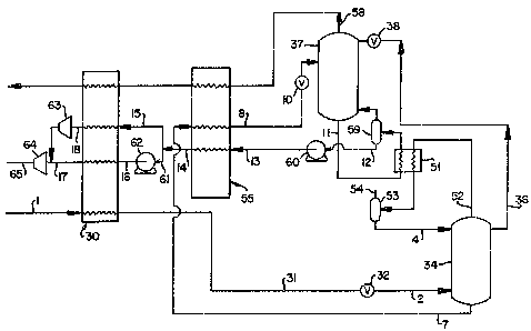
.
Figure 1 is a schematic flow diagram of one
preferred embodiment of the high pressure methane
gas production process of this invention wherein a
double column cryogenic rectification plant is
employed.
1297780
--5--
Figure 2 is a schematic flow diagram of one
preferred embodiment of the high pressure methane gas
production process of an invention whereln a single
column cryogenic rectification plant is employed, as
claimed in copending Canadian application Serial
No. 615,581 filed December 20, 1989, divided out of this
application.
DETAILED DESCRIPTION
The invention will be described in detail
first with reference to Figure 1 which illustrates the
process of this invention with use of a double column
cryogenic rectification plant.
Referring now to Figure 1, gaseous feed
stream 1 which comprises nitrogen and methane and is
generally at a pressure exceeding about 500 psia is
cooled by passage through heat exchanger 30 to produce
cooled gaseous feed 31. This cooled gaseous feed is
expanded, such as by passage through valve 32, to
partially liquify the feed, and the two phase feed 2 is
introduced into higher pressure column 34 of a double
column cryogenic rectification plant.
In the separation plant the feed is
rich li~uid separated by rectification into methane and
nitrogen rich vapor. Referring back to Figure 1, feed 2
is introduced into higher pressure column 34 which is
operating at a pressure within the range of from 250 to
450 psia, preferably within the range of from 300 to 400
psia. Within high pressure column 34 the feed is
separated into nitrogen vapor and methane-richer liquid.
Nitrogen ric~er vapor is withdrawn 52 and passed through
heat exchanger 51 wherein it is partially condensed and
then passed to phase separator 53 wherein it is
separated into vapor and liquid. When helium
lZ97780
--6--
recovery is desired the vapor 54 is further
processed in a helium recovery unit. Additional
processing can include cooling with partial
liquefaction and separation at the cold end of the
process and upgrading at the warm end of the process
such as by pressure swing adsorption. A crude
helium stream can be recovered directly as shown in
Figure 1. The liquid 4 is returned to column 34,
and also passed through line 36 and valve 38 to
col D 37, as liquid reflux.
Methane rich liquid 7 is withdrawn from
column 34, cooled by passage through heat exchanger
55, expanded through valve 10, and passed into lower
pressure column 37 which is operating within the
range of from 12 to 40 psia, preferably from 20 to
30 psia.
Within column 37 there is produced nitrogen
top vapor and methane bottom liquid. The top vapor
58 is rewarmed in heat exchangers 55 and 30 and may
be recovered for use or released to the atmosphere.
Optionally a portion of cold vapor 58 can be used in
a helium processing unit.
Methane liquid, which comprises generally
at least 90 percent methane and preferably at least
96 percent methane, is withdrawn 11 from column 37,
partially vaporized by indirect heat exchange
through heat exchanger 51 against top vapor from
column 34, and passed to phase separator 59. Vapor
from phase separator 59 is returned to column 37
while remaininq liquid 12 i6 pumped, such as by pump
60, to a higher pressure which generally will be at
le~ast 200 psia, and preferably will be within the
~2~7780
--7--
range of from 300 to 350 psia. The higher pressure
methane liquid 13 is warmed by indirect heat
exchange by passage though heat exchanger 55 against
cooling higher pressure column bottoms to result in
warmed pumped methane liquid 14. The temperature
that the pumped methane liquid 14 is warmed to is
dependent on the column pressure level. At lower
pressure levels (high pressure column of 250 psia)
the liquid can be warmed to about 125 K whereas at
higher pressure levels (high pressur~ column of 450
psia) the liquid can be warmed to about 145 K.
Generally the pumped liquid will be warmed about 10
K prior to further pumping.
At least a portion 61 of methane liquid 14
is further pumped, such as by pump 62, to a pressure
of at least 400 psia and preferably at least 500
psia and the resulting methane liquid 16 is
vaporized by passage through heat exchanger 30
against cooling gaseous feed 1 to produce high
pressure methane gas 17 which is at a pressure
essentially the same as that of liquid 16. Pcrtion
61 may be from 25 to 100 percent of stream 14 and
preferably is from 25 to 50 percent of stream 14.
When portion 61 is less than 100 percent of stream
14, remaining portion 15 is vaporized by passage
through heat exchanger 30 against cooling gaseous
feed 1 to produce methane gas 18. Gas 18 may be
compressed 63 and combined with stream 17 and the
combined stream further compressed 64 to produce
methane gas 65. ~y gainfully employing
refrigeration from the rectification plant to enable
staged pumping of methane liquid, the product end
12~7780
--8--
compression requirements, such as by compressors 63
and 64, are significantly reduced and energy savings
are attained.
Figure 2 illustrates a preferred embodiment
of the process of this invention with use of a
! single column cryogenic rectification plant. The
choice of using either a double column or a single
column plant is an engineering decision which can be
made by anyone skilled in this art. Generally a
double column is preferred when the feed comprises
25 percent or more of nitrogen and a single column
plant is preferred when the feed contains less than
25 percent nitrogen.
Referring now to Figure 2, gaseous feed
stream 40 which comprises nitrogen and methane and
is generally at a pressure exceeding about 500 psia,
is cooled by passage through heat exchanger 41 to
produce cooled gaseous feed 42. This cooled gaseous
feed is expanded, such as by passage through valve
43, to partially liquefy the feed, and the two-phase
feed 24 is introduced into single column cryogenic
rectification plant 45. Column 45 is operating at a
pressure within the range of from 250 to 450 psia,
preferably from 300 to 400 psia. Within column 45
the feed ie separated into nitrogen top vapor and
methane bottom liquid. The nitrogen top vapor is
withdrawn 46, partially condensed against
recirculating heat pump fluid in heat exchanger 47,
passed to separator 48 and separated into vapor and
liquid. The liquid 70 is returned to column 45 as
liquid reflux. The top vapor 49 is rewarmed in heat
exchanger 41 and may be recovered for further use or
1~7780
released to the atmosphere. Optionally cold vapor
49 can be further processed for helium recovery. In
another option, a portion of cold vapor 49 can be
used in a helium recovery process.
The heat pump circuit comprises heat pump
fluid 20, which is generally methane, recircula~ing
through heat exchangers 72, 73, 74 and 47 and
further comprises compression 28 of the heat pump
fluid after the traverse of hea~ exchanger 72 and
10 expansion 19 of the heat pump fluid prior to the
traverse of heat exchange 47. As can be seen, the
heat pump circuit is self-contained and independent
of column 45.
Methane liquid, having a methane
15 concentration generally at least 90 percent and
preferably at least 96 percent, is withdrawn from
column 45, partially vaporized by passage through
heat exchanger 73 against recirculatinq heat pump
fluid and passed to phase separator 76 wherein it is
20 separated into vapor 5, which is returned to column
45, and into remaining liquid 6. Liquid 6 is
divided into first portion 8 and second portion 9.
First portion 8 comprises from 10 to 50 percent and
preferably from 25 to 50 percent of remaining liquid
25 6, and second portion 9 comprises essentially all of
the rest. First portion 8 is expanded through valve
77 to a pressure within the range of from 200 to 400
psia, and preferably within the range of from 250 to
300 psia, and expanded first portion 23 is warmed
30 and vaporized by indirect heat exchange with cooling
gaseous feed in heat exchange 41 to produce methane
gas 78. Second portion 9 is pumped, such as by pump
1;:97780
--10--
79 to a high pressure of at least 500 psia and
preferably at least 550 psia. High pressure second
portion 21 is then heated and vaporized by indirect
heat exchange with cooling gaseous feed in heat
exchange 41 to produce hiqh pressure methane gas 80
! which is at a pressure essentially ~he same as that
of liquid 21. Methane gas 78 may be compressed 81
and combined with stream 80 and the combined stream
further compressed 82 to produce methane gas 65. By
gainfully employing refrigerat;on from the
rectification plant to enable pumping of methane
liquid, the product end compression requirements,
such as by compressors 81 and 82, are significantly
reduced and energy savings are attained.
The following tabulation in Table I
represents the results of computer simulation of the
process of this invention carried out with a double
column separation plant and the warmed pumped
methane liguid divided into two portions. The
stream numbers in Table I correspond to those in
Figure 1.
~297780
X :~:
W W Z Z
V~ ~,
o ~ ~
_ ly Z o ,~ o o o
I S ~ ~ ~ r~) r~
I
3: I.J 2
I v7 1-- ~7 ~ o ~1 ~`
L.J
~C
r = $ ~ _ u~ O O O
'7 ~ ~ o ~0 ~ ~
~ _
~Y I
I S J
-
32 CC
Z Q ~I ~ O o O
~ ~ _ ~ I a~
~ O N O ~ N
3 0 ~ o
o @ ~ ~ N
i
U O ~ = C
129'7780
-12-
The following tabulation in Table II
represents the results of a computer simulation of
the process of ~his invention carried out with a
single column separation plant, The stream numbers
in Table II correspond to those in Figure 2.
!
~297780
,
.~ Z
O ~ O ~ In O O
_ g ~J N ~
r ~
Q z o ~ o o
o ~ ~
_ ~. 3o u~ o ~
o S ~ _ ,~ o , ~ ,~
~ s 2 ~ ~ ~
~ ..
3 _ _ o o
~ ~ o ~
: - s . 2
h
~ S
S ~, ~ ~ O I
S J ~ _
S ~ r~ _
O @ ~ _ ~ ~ U~
C~ O O O U~
;~i l" C~l O
~O
~ O
Z ~,~
o ~
, . . .
~Z97780
Now, by the process of this invention, one
can effectively employ excess refrigeration within a
cryogenic nitrogen rejection plant to increase the
pressure of withdrawn methane liquid by selective
additional liguid pumping wherein the energy input
! associated with such liquid pumping is allowed by
the available excess refrigeration, thus enabling
production of methane gas product at high pressure
and consequently reducing product methane gas
compression requirements. Compression energy
reduction of up to about 25 percent is attainable by
use of the process of this invention.
Although the process of this invention has
been described in detail with reference to certain
specific embodiments, those skilled in the art will
recognize that there are other embodiments of this
invention within the spirit and scope of the claims.