Note: Descriptions are shown in the official language in which they were submitted.
~29~3S;
TECHNICAL FIELD
This invention rela~es to a wavelength locked pulsed dye laser system
and a method of operating a pulsed dye laser system to provide a wavelength
locked pulsed laser light. ~~
BACKGROUND ART
There are a wide variety of fields which utilise laser light. A
particular application is in the treatment of human cancer tumours. It has
been established that illumination of tumours previously labelled with
suitable photoactive substances (for example, HPD - haematoporphyrin
derivative) is an effective method of treating such tumours. The
wavelength (colour) of the illumination light must be such that interaction
with the photoactive substance occurs while at the same time adequate
penetration of the tissue is permitted. In the case of the drug HPD, for
example, photoactivity occurs for wavelengths in a narrow band (t 5nm)
centred at 630nm while good transmission of light through haemoglobin and
thus through the tissue is obtained for wavelengths greater than 600nm.
Both continuous and pulsed light have been used for the above
purpose. Continuous light sources employed to date have been conventional
arc discharge lamps of high intensity used with appropriate filters or a
continuous dye laser pumped by an argon ion laser. Pulsed light of the
desired wavelength and average power can be obtained using a gold vapour
laser, which operates directly within the required band at 628nm or a
pulsed dye laser pumped by a pulsed copper laser and whose wavelength is
tuned in the requlred band. Given that fibre-optics are required to
deliver the light to tumour sites within the body, laser sources are
preferred over conventional sources (for the purposes of efficient coupling
of light into the fibres). Moreover there is evidence that pulsed lasers
are superior to continuous lasers in therapeutic effect.
Continuous dye lasers pumped by argon ion lasers have been found to
` 30 have considerable dis)dvantages in practlce fo~ the above application.
~2~7935
These systems are complex requiring delicate alignment which can alter ov~-
time and are therefore unreliab1e for routine use; they are also very
expensive to install and maintain and electrically extremely inefficient.
The gold vapour laser, though generating emission directly within t~
required band at the appropriate energy densities, also has significant
disadvantages in practice. The very high operating temperatures, greater
than 1750~C, required of the plasma tube place great stress on the
construction materials; the low energy conversion efficiency (compared ~it-
the copper vapour laser) results in stress on the high-voltage electrical
excitation circuitry and components and places added requirements on
cooling facilities; and the laser material (gold) is expensive in the
quantities required. All these factors combine to make the gold laser als~
unreliable in operation and expensive to install and maintain.
Pulsed dye lasers based on the pulsed copper laser as a pump source
have considerable advantages over both the argon-pumped dye laser and the
gold vapour laser. rn the first place the copper laser pump source itself
is a practical and reliable device (with plasma tube operating temperatures
only about 1500C), relatively cheap to install and maintain and having
good electrical energy conversion efFiciency. Second, the efficiency of
conversion of the copper laser pump power (at wavelengths in the green and
yellow) to high-pulse-rate dye laser output (at wavelengths in the orange,
red and infrared) is high, up to 50%, in direct conversion amplifiers.
However to achieve such high conversion efficiencies a dye amplifier must
be in~ected with an optical signal at the appropriate wavelength within the
amplification band of the dye and with sufficient Initial power. Such an
lnjection signal is normally provided by a dye oscillator also optically
pumped with a portion of the copper laser pump power. Copper-laser-pumpe~
dye oscillators are themselves relatively inefficient (< 15%) in
convertin9 the pump laser power to dye oscillator output. The optical
arrangements of dye oscillators are usually complex including a loss
. fJF/31f -4-
.
~l2979~
causing frequency-selective element (often a diffraction grating) as part
of the optical cavity, and, in many cases, additional optical components
(lenses or prisms) to expand the optical beam at the grating. Although
~-~ such dye oscillators have the advantage that the operating wavelength is
tunable over the amplification band of the dye used in the oscillator, the
tolerance to misalignment can be low and, in applications where a fixed
operating wavelength is required, wavelength and power stability are
difficult to achieve. Moreover the optical quality of such dye oscillator
output beams is low, often requiring very inefficient beam clean-up
techniques to be applied before injection into the subsequent dye
amplifier(s).
It follows from above that there is a need for a wavelength locked
pulsed laser light source where the wavelength of the laser light is near
630nm. It is the object of the invention to provide a wavelength locked
pulsed laser with high average power at good overall efficiencies (, 20%)
and with low beam divergence (< 1 mrad).
DrSCLOSURE OF INVENTION
-
The present inventors have discovered that the wavelength of pulsed
laser light emitted from high average power copper laser pumped pulsed dye
lasers can be efficiently (> 90%) locked at the wavelength of laser light
from a low-power (~ 5 m~) continuous wave laser directed into the optical
cavity of the dye laser. This result is novel since it has been previously
shown that low-power continuous laser light directed into high gain short
pulse (< 50 nsec) dye laser optical cavitles is ineffective in locking
the wavelength or controlling beam characteristics of the pulsed laser
light emitted from the dye laser under conditions appropriate to efficient
energy conversion in the dye laser. (It has been reported previously'
that locking efficiencies up to 50% can be achieved only for very low
energy conversion efficiencies < 1% for short optical pulses of < 50
nsec). The reason for this is that the spontaneous fluorescent emission
FJF/31F -5-
~L29~79:35
62616-95
from the dye pumped by short (~ 50 nsec) pulses of hi.gh peak power
l~lO kW) is comparable to the injec-ted intensity from the low-
power continuous laser.
According to a first aspect, the invention provides in
a wavelength locked pulsed laser system, the improvement comprising
a low-power continuous wave laser disposed to inject a continuous
wave, single wavelength, laser light emission therefrom into an
optical cavity of a high power short pulse dye laser, the dye
laser being transversely pumped by a beam line-focused with
respect to the continùous wave emission, the optical cavity of
the pulsed dye laser further comprising a short cavity bounded by
first and second mirrors aligned normal to a central axis, the
mirrors having a coating for suppressing laser emissions of
wavelengths other than those close to the continuous wave, single
wavelength. emission, whereby the wavelength of pulsed laser light
emitted from the dye laser is locked at the wavelength of the
continuous wave, single wavelength, laser light.
According to a second aspect, the invention provides in
a wavelength locked pulsed laser system, the improvement comprising
a low-power continuous wave laser disposed to inject a continuous
wave, single wavelength, laser light emission therefrom into an
optical cavity of a high power short pulse dye laser, the optical
cavity of the pulsed dye laser further comprising a short cavity
bounded by first and second mirro:rs aligned normal to a central
axis, the mirrors suppressing laser emissions at wavelengths
other than those close to the conti.nuous wave, single wavelength
~2~7~3S
62616-95
emission , whereby the wavelength of pulsed laser light emitted
from the dye laser is locked at the wavelength of the continuous
wave, single wavelength, laser light.
According to a third aspect, the invention provides a
method of producing a wavelength locked, pulsed, laser emission
comprising the steps of: emitting a first high power short pulse
beam; emitting a second low-power continuous wave beam; focusing
the first beam to a line; projecting the focused first beam
transversely to the second beam and onto it and onto a stream of
laser dye which is disposed between two mirrors which define a
short, straight optical cavity having a central optical axis which
passed through the first beam; projecting the second beam along
the central optical axis; and suppressing the emission from the
optical cavity of wavelength, other than the wavelength of the
second beam.
According to a fourth aspect, the invention provides
a method of producing a wavelength locked, pulsed, laser emission
comprising the steps of: emitting a first high power short pulse
beam; emitting a second low-power continuous wave beam; projecting
the first beam onto the second beam and onto a stream of laser
dye which is disposed between two mirro.rs wh:ich define a short,
straight optical cavity having a central optical axis which passed
through the first beam; projecting the seconcl beam along the
central optical axis; and suppressing the emission from the op-
tical cavity oE wavelengthl other than the wavelength of the
second beam.
- 6a -
, . . .
~2~7~3~;
62616-95
The power of the continuous wave laser can be signi-
ficantly lower than the power of the pumping light of the pulsed
dye laser, e.g. a continuous wave He-Ne laser of less than 5
milliwatts power has been used to lock the wavelength of a dye
laser employing rhodamine 640 or rhodamine 640 - rhodamine 590
mixtures or DCM as the fluorescent dyes and a 4W copper laser input
pumping light. Preferably the continuous wave laser is from O.lmW
to lOmW and the pulsed dye laser is pumped by a 0.5W to lOW
copper vapour laser.
While the invention is particularly described below
with reference to a dye laser employing rhodamine 640~ Kiton Red
620 dye, rhodamine 590, rhodamine 640 - rhodamine 590 mixtures
or DCM as the dye laser medium
- 6b -
: ,
~t" " ,,
~:97~3135
optically pumped by the green (~ = 510.6nm) and/or yellow (~ = 578.2
nm) emissions from a high-pulse-rate copper vapour laser and locked to the
wavelength (~ = 632.8nm) of a low-power continuous-wave (cw) helium-neon
laser, it is not limited to these particular~(pump or locking) laser
wavelengths. In particular, the invention includes situations such as (i)
high-pulse-rate, short-pulse pulsed laser pump sources other than the
copper vapour laser including other pulsed metal vapour laser such as gold,
manganese or lead vapour lasers, or the metal atom recombination lasers
such as strontium and calcium ion lasers, or any other high-pulse-rate
lasers; (ii) low power (0.1 milliwatt < power < 5 milliwatt depending
on power of pulsed dye laser) lasers other than the helium-neon laser for
wavelength-locking purposes including metal ion lasers such as the cadmium,
zinc, mercury, or selenium ion lasers, or low-power noble-gas ion lasers
such as argon or krypton ion lasers, or semi-conductor diode lasers, or any
other low-power continuous-wave lasers. It is noted that continuous wave
lasers of power > 5 milliwatt can also be used in the first and second
embodiments of this invention.
The locked pulsed laser light can be injected into a dye amplifier(s)
to increase its power to a preselected level.
In the present invention the wavelength locking is achieved using a
low power continuous laser, the optical cavity of which is coupled to the
dye cavity in close proximity. The reflectlvity/transmission profiles of
the mirrors defining the optical cavity of the pulsed dye laser are chosen
to suppress laser emission at wavelengths other than those close to the
wavelength of the continuous low power in~ection laser. In addition, some
optical dispersion in the dye laser cavity is provided for to aid
suppression of unwanted wavelengths.
The separation of mirrors defining the optical cavity of the pulsed
dye laser is small.
The laser light from the continuous wave laser can be polarised or
,
- FJF131F _7_
~2~35
unpolarised.
The wavelength locked pulsed laser light source can include a
continuous wave laser ~hich is a 0~5mW -to 5mW helium-neon laser, the pulsed
-- dye laser employs a rhodamine 640, rhodamine S90, DCM, rhodamine 640 -
rhodamine 590 mixture or Kiton Red 620 dye and the pulsed dye laser is
pumped by a 2W-5W copper vapour laser.
The invention provides locking of pulsed laser light emitted from a
pulsed dye laser of short pulse duration (< 50ns) to the wavelength of
laser light emitted from a continuous wave laser into the optical cavity of
the dye laser and giving stable efficient conversion of optionally
high-pulse-rate short-pulse, high peak power pump laser power tat the pump
wavelength) to optionally high-pulse-rate, short-pulse, high peak power dye
laser output power (at the locked wavelength) with high optical beam
quality. Further, alignment of the dye laser mirrors is relatively easy to
reproduce as alignment can be simplified to a one mirror adjustment. The
high optical quality of the frequency-locked output beam which stems from
the high optical quality of the low-power locking laser beam is
demonstrably superior to the output beam quality of conventional (tunable)
pulsed dye lasers.
ZO In terms of one of the applications envlsaged for the invention (viz.
~IPD cancer phototherapy) the present invention based on a copper
laser-pumped dye laser locked to the wavelength (~ = 632.8nm) of the
He-Ne laser has considerable operational advantages over the alternative
laser systems as described above.
BRIEF DESCRIPTION OF DRA~INGS
Preferred embodiments of the invention are now described, with
reference to the following drawings in which:
Fig. 1 is a schematic depiction of a pulsed dye laser pumped by a
short-pulse high-peak power laser source and a continuous wave laser
disposed to inject continuous wave, single wavelength, laser llght emitted
FJF/31F -8-
, . .
.
~2~7~3~
therefrom into the optical cavity of the pulsed dye laser;
Fig. 2 is a schematic depiction of the arrangement of Fig. 1 except
that mirror M4 is a totally reflecting mirror and a beamsplitter BSl is
located ~ithin the optical cavity of the dye laser;
Fig. 3 is a schematic depiction of the arrangement of Fig. 1 except
that mirror M4 is a totally reflecting mirror and a grating Gl is located
within the optical cavity of the dye laser;
Fig. ~ is a schematic depiction of the arrangement of Fig. 1 except
that the dye pumping laser is focussed by a spherical mirror or lens to a
spot on a fast flowing dye stream;
Fig. 5 is a schematic depiction of the arrangement of Fig. 1 except a
ring cavity, rather than standing wave cavity, is used; and
Fig. 6 is a schematic depiction which includes the arrangement of
Fig. 1 in combination with a dye laser amplifier.
MODES FOR CARR~ING OUT THE INVENTION
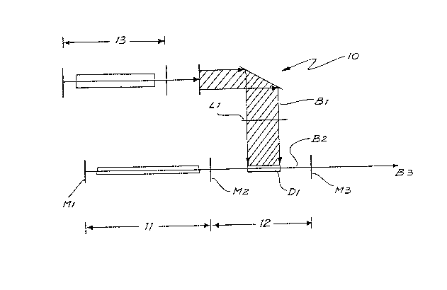
Referring to Fig. 1 a wavelength locked pulsed dye laser light system
10 includes a He-Ne continuous wave laser 11 which is disposed to inject
continuous wave, single wavelength (~ = 632.8nm) laser light emitted
therefrom into the optical cavity 12 of a pulsed dye laser.
Incoming pump beam Bl from copper vapour laser 13 containing green
(~ = 510.6nm) and/or yellow (~ = 578.2nm) wavelengths is line-focussed
by cylindrical lens Ll (or a combination of cylindrical and spherical
lenses) onto dye cell Dl in a directlon transverse (that isl perpendicular)
to the optical axis of cavity 12. Dye cell Dl contains a flowing solution
of a sultable fluorescent laser dye such as rhodamine 590, rhodamine 6~0
(or mixtures of the two), Kiton Red 620, DCM or other appropriate dyes or
dye mixtures. He-Ne laser 11 and its end-cavity mirrors Ml and M2 are
aligned with the optical axis of cavity 12. Mirror M2 may be wedged to
introduce dispersion into the cavity. Mirror M3 which partially reflects
output beam B2 of He-Ne laser 11 is accurately aligned normal to B2 so that
FJF131F _g_
~29~313~
mirror M3 forms part o~ a three-mirror cavity for ~le-Ne laser 11 (along
with Ml and M2). ~hen He-Ne laser beam is not present (that is, He-Ne
laser 11 is turned off) cavity 12 emits a laser beam at B3 with a broad
spectrum characteristic of the amplification properties of the dye and the
reflection properties of M2 and M3 and any dispersion in the cavity. When,
however, the He-Ne laser beam is present in cavity 12 (He-Ne laser 11 is
turned on), the output wavelength at B3 of cavity 12 becomes locked to that
of He-Ne laser 11 (at g = 632.8nm) with high spectral purity. The distance
between M2 and M3 is a critical parameter for optimum performance as is the
power of He-Ne laser 11 in determining the spectral purity and stabilit~.
Such cavi-ty lengths as 70 to 300nm are typical though others are allowed.
The polarisation of He-Ne laser beam B2 can be unpolarised or linearly
polarised; in the latter case the plane of polarisation can be parallel or
normal to pump beam direction Bl. The transmission of mirrors M2 and M3
are typically 0.5-2.0% and 10-80% respectively at ~ = 632.8nm; other
transmissions are allowed for. The dye cell itself may be wedged to
provide further optical dispersion ~n the dye laser cavity.
In Fig. 2 partially reflecting (transmitting) mirror M3 of Fig. 1 is
replaced by a totally reflecting mirror M4 and output beam B3 from the d~e
laser taken from a variable coupling-plate or beamsplitter BSl within the
dye laser cavity between M2 and M4.
In Fig. 3 an additional component, grating Gl, is added to the dye
laser cavity between M2 and M4; grating Gl is oriented so that the first
(or higher) order diffraction of He-Ne beam B2 is colinear with the dye
laser optical axis. Output beam B3 of the dye laser is taken from the
grating as the zeroth (or other) diffraction order. Other arrangements of
gratings or alternative dispersive elements including a prism or prisms are
envisaged, in particular the replacement of mirror M4 in Fig. 2 with a
broadband-reflecting Littrow prism.
In Fig. 4 the transverse pumping arrangement is replaced by a
FJF/31F -10-
~2~7~3~5
longitudinal pumping arrangement where the input (copper laser) pump beam
is ~ocussed by a spherical ~irror or lens to a spot on a fast flowing dye
stream (in a closed cell or free jet) oriented at Brewsters angle to the
dye-laser optical axis. The dye laser cavity is otherwise unaltered from
that of Fig. 1 Alternative arrangements of the dye laser cavity such as
are illustrate~ in Figs. ~ and 3 but employing longitudinal pumping as in
Fig. 4 are envisaged.
In Fig. 5, the standing wave cavity (figures 1 ) 4) is replaced by
a ring cavity comprising mirrors M2, M3 and M4. The He-Ne injection
locking signal is coupled into the cavity through mirror M2 (also the
output coupler of the He-Ne laser) and the output from the locked
oscillator eNtracted for either M3 or M4. Other arrangements incorporating
additional mirrors, mirror and prism or prism cavities are envisaged.
Fig. 6 sho~s the dye laser oscillator as illustrated in Fig. 1
employed in conjunction with dye amplifiers (oscillator cavities such as
those of Figs. 2-4 may be substituted for that of Fig. 1). The input
(copper laser) pump beam is split at beamsplitter BS2, a fraction of the
beam being redirected to the dye oscillator as for Fig. 1. The remaining
pùmp beam passes to beamsplitter BS3 where a further fraction is redirected
to dye amplifier DlA, via focussing optics L2. The dye amplifier contains
a flowing solution of a fluorescent dye or dye mixture as described for the
dye oscillator. Output beam B3 of the dye oscillator passes through beam
transfer optics BTl (which might include apertures, lens or dispersing
elements or a combination of such as is required to effect any desirable
clean-up of the oscillator beam) to the dye amplifier and emerges as a
power-amplified beam at B4. This amplified beam may be employed directly
or further amplified after passage through beam transfer optics BT2 to an
additional dye amplifier stage.
As an example, for a 4 Watt copper laser input pump beam, some 30% or
about 1-1.5 W may be employed to pump the fixed-wavelength oscillator
FJF/31F -11-
.
~7~
generating approximately 0.1 W at ~ = 632.8nm from the oscillator.
Injection of this output beam into an amplifier, pumped by the remaining
2.5-3W of the copper laser pump beam results in amplification by a factor
~-~ ,typically~ to generate a 1 Watt output beam (B4) at ~ = 632.8nm at
overall conversion efficiency 25% from the original copper laser pump
beam. Alternatively, a single-step conversion efficiency near 20% may be
obtained from a single frequency locked dye oscillator pumped with 3-4
Watts direct input. Note that arrangements similar to that of Fig. 6 but
where the dye amplifiers are pumped transversely from both sides are also
envisaged.
A feature of the output beams generated by the devices described
herein is excellent pGwer and wavelength stability in high-average-power,
high-pulse rate operation.
References
1. Vrehen, W.M.F. and Breimer, A.J. Opt. Commun. 4 (1972) 416
FJF/31F -12-