Note: Descriptions are shown in the official language in which they were submitted.
g795~
-- 1 --
PROTECTIVE TRIGGERING OF THYRI STORS
I N A PULSE GENERATOR
The invention relates to a method of and an
apparatus (circuit) for protecting the thyristors of
a pulse generator of a pulse operated electrostatic
precipitator.
In a pulse operated electrostatic precipitator
the voltage pulse is provided by triggering a switch
element, usually a thyristor or a circuit consisting
of series and/or parallel coupled thyristors. When
the pulse has reached its peak the current in the
thyristors ceases as during the pulse decay, the
current flows ~n return diodes which are coupled in
parallel with the thyristors. Once the current in
the thyristors has ceased for a certain period of
time, the recovering time, they become non-conductive
in their forward direction until they are retriggered
to provide a new pulse.
If a spark-over occurs in the electrostatic
precipitator after the current in the thyristors has
ceased, but before the recovery time has elapsed, the
thyristors will become forward biased and current
will be drawn through the thyristors even though they
are only partly conductive. In such a case the
current is concentrated in separate, still partly
conducting areas of the thyristor se~i-conductor
chips with the result that these are consequently
overloaded and possibly damaged or destroyed.
EP-A-0066950 and EP-A- ~ escribe methods
by which retriggering of the thyristors of the pulse
generator is established when spark-overs in the
electrostatic precipitator are detected. Such a
retriggering means that the thyristors can take over
the current again without the danger of overload,
,,~ ~
~L~t~ 353
-- 2 --
provided that the retriggering signal has been established by
the time the current shifts from the return diodes to the
thyristors.
In the narrow interval of time from the moment that the
current has shifted from the thyristors to the return diodes and
for a few micro-seconds afterwards~ due to unavoidable reaction
times in the retriggering system, it is difficult to ensure that
the retriggering signal can be established by the time that the
current shifts back to the thyristors as a consequence of
precipitator spark-over.
This is particularly so in extreme operating situations
where a low voltage pulse height is used in the electrostatic
precipitator simultaneously with use of a high DC voltage.
Under these circumstances the time from the occurrence of the
spark-over until the current will try to flow in the thyristors
will be fractions of a micro-second.
As the time required for detecting the spark-over and
generating the retriggering signal typically is one or two
micro-seconds, the retriggering signal will consequently be too
late.
The object of the invention is to provide a method and
circuit which ensure that the entire critical area is covered by
the protective triggering signal.
More particularly in accordance with the invention there
is provided, a protector triggering circuit for a thyristor
switch element of a pulse generator, said pulse generator having
a pulse circuit, said protective triggering circuit comprising:
a high frequency current transformert said current
transformer haviny a primary winding and a secondary winding,
said primary winding being series-coupled with said pulse
circuit o~ said pulse generator;
a resistance coupled in parallel across said secondary
winding thereby to provide a current-representing voltage signal
thereacross in use;
~7~i3
a peak value measuring unit for measuring said
current-representing voltage peak value;
a voltage divider connected to said peak-value measuring
unit for providing a signal proportional to said peak-value
signal;
a voltage comparator connected to said resistance and said
voltage divider for comparing said current representing voltage
with said peak-value proportional signal, said comparator having
an output to indicate whether or not said peak-value
proportional signal exceeds said current representing voltage,
and
a timer circuit connected to said comparator and having an
output trigger signal activated by said voltage comparator
output signal indicating said peak-value proportional signal
exceeding said current representing voltage; and
an amplifier connected to said timer circuit to provide an
output protective trigger current for said thyristor.
In accordance with a second aspect of the invention there
is provided, a method of protecting a thyristor o~ a pulse
generator circuit, said pulse generator circuit controlling a
pulse operated electrostatic precipitator, wherein said pulse
generator circuit includes the thyristor and a return diode, the
current in said circuit being shi~table between said thyristor
and said return diode,
said method comprising,
feeding said thyristor with a protective trigger signal
within a time interval covering the period from immediately
before that at which said pulse current shifts from said
thyristor into said return diode to an instant during the
aonductive interval o~ sa.id return diode,
said protective trigger signal b0ing ~ed to said thyristor
during said period whereby;i~ said current suddenly changes
direction due to an electrical spark-over in said electroetatic
precipitator,it can flow back into said thyristor which has been
~ .
-- 4 --
triggered on by said protection trigger signal following said
spark-over.
Every spark-over occurring during this interval will
consequently result in the thyristors taking over the current
without problem, as the protective triggeriny signal will
already have been established. If the spark-over occurs at an
instant after the protective triggering has ceassd, the current
in the return diodes will have reached such high value that the
time from the spark-over until the current tries to shift from
the return diodes to the thyristors is suf~iciently long to
establish the normal retriggering signal.
If no spark-over occurs during the pulse period, the
protective triggering signal has no damaging effect, provided
that the pulse duration has been chosen so that the time from
the ceasing of the protective triggering signal and until the
ceasing of the pulse is longer than the recovery time of the
thyristors.
Embodiments of the invention will now be described in more
detail with reference to the accompanying drawings, in which:
Figure 1, in block diagram form, shows a protective
triggering system embodying the invention;
Figure 2 shows the timing of the signals, in the system
during a normal pulse; and
Figure 3 shows the timing of the signals in the system
during a spark-over.
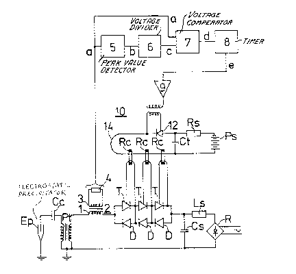
Figure l shows a pulse cirauit comprising a rectifier
system R converting alternating current ~rom a mains supply into
DC. The DC is led through a series inductance Ls for loading a
skorage capacitor Cs (which in this embodiment acquires a
negative charge at its junction with inductance Ls). The
storage capacitor may be discharged to provide a pulse current
through a pulse transformer Pt ~rom the secondary winding of
which a high tenslon pulse is led through a coupling condenser
Cc to the emission electrode oE an electrostatic precipitator Ep.
The discharge of the storage capacitor is obtained through
~$~3
- 5 ~
triggering the thyristors T in a column of anti-parallelly
coupled thyristors T and diodes D. The use of such a column i5
necessitated by the fact that a single thyristor or diode cannot
alone block for the voltage applied to the column. The column
is here only shown schematically as it further comprises
capacitors and resistances to distribute the voltage drop
uniformly over the column.
To trigger all the thyristors in the column simultaneously
a cable firing system 14 may be usedO In such a system the
trigger circuits of the thyristors are each coupled to a winding
on an individual ring core transformer and a cable is led
through all the ring cores. A pulse current through the cable
will then induce trigger current in all the individual trigger
circuits of the thyristors in the column.
In figure 1 is shown only the trigger system for an
emergency firing system. A trigger condenser Ct charged from a
DC power supply Ps through a series resistance Rs. When a
thyristor 12 is triggered the condenser Ct is discharged through
a cable passing through ring cores Rc and a trigger current is
induced in the trigger circuits of the thyristors T.
Figure 1 shows the primary winding 1 of a high frequency
current transformer 2 coupled into the pulse circuit of a pulse
generator (not shown). Consequently both the thyristor current
through thyristors T and the return diode current through diodes
D flow therethrough. As a consequence a voltage will be
generated across the secondary winding 3 which is loaded by a
resistance 4, this voltage being proportional to the current in
the pulse circuit. The voltage signal generated, calculated in
relation to a fixed rePerence, is referred to as a. The
polarity of the signal a has a positive value when current is
passing through the thyristors T and a negative value when
current is passing through the return diodes D.
~ he voltage signal a is passed to a peak value detector 5,
the output signal b of which is set to equal the highest
~7~3~;3
positive value of signal a. Prior to each new pulsa it must be
ensured that the signal b of the peaX value detector has been
reset to zero. This is most easily achieved by discharging the
memory element of the peak valus detector, which element is
normally constituted by a capacitor, at a suitable time constant
interval.
The signal b is passed to a voltage divider ~, which
provides a signal c constituting a suitable fraction of signal
b. Signal c is passed to one of the inputs of a voltage
comparator, and signal a to the other.
The voltage comparator gives off a signal d when the value
of signal c is larger than or equals that of signal a, and the
signal d is passed to a timer circuit 8 adapted to give of~ a
signal e for some time after a positive shift in signal d.
The signal e is passed to an amplifier circuit 9, to the
output of which there is coupled a cable ignition system lo
which triggers the series and/or parallel coupled thyristors
constituting the pulse generator switch element.
As well as being connected to the above described
protective triggering system the cable ignition system is
connected to the normal triggering system which starts the pulse
and to the retriggering system which is actuated by the
spark-over detection such as described for instance in
EP~A-0066950.
Figure 2 shows the timing of the signals a to e during a
normal pulse. The figure ~urther includes a depiction of the
precipitator voltage U, indicating both the DC voltage level and
the superimposed pulse voltage, the pulse starting at time t1.
The signal a is the voltage signal representing the
current in the pulse circuit and is e~fectively a sine wave
signal. The signal h indicates substantially the highest
positive peak value obtained by signal a. Once the peak value
of a has been attained at t2, the value of b gradually descends
at a rate high enough to ensure that the value o~ b is close to
~7~;3
- 6a -
zero before the next pulse is given off, but not 50 high that
the value deviates signi~icantly from the ideal peak value
within the pulse period (tl to t6).
Signal c is proportional to signal b, but with a
value corresponding e.y. to one fifth of b. Signal
d is a logical signal which is high for so long as
'' '
9~3
signal c is higher than or equals signal ~.
Immediately following the instant tl signal becomes
lower than signal a, so that signal d is subsequently
low.
At t3 the signal a becomes low~r than the
signal c which at that instant has a size o~ e.g. one
fifth of the peak value of a, which occurred at t2~
As signal a substantially follows a sine curve,
the occurrence at t3 will happen at arc sine of one
fifth, corresponding to 11.54 before a becomes zero
which occurs at t4.
When signal a at t3 becomes lower than signal
c, signal d immediately shifts to a high level, which
entails also that signal e increases and remains high
during the period t3 to ts. As the protective
triggering signal is controlled by signal e it is
seen that the protective triggering signal is
established in the moment the current shifts rom the
thyristors into the return diodes at t4. Thus it is
ensured that complete protection exists in the entire
critical area.
In the period from ts to t6 the thyristors turn
off and recover their hold-off strength, and at t6
the pulse period ceases.
; 25 Figure 3 shows the signal timing during a pulse
during which a spark-over occurs. At tll the pulse
is started, and signal a attains its peak value at
tl2, which value is maintained in signal b. At tl3
signals a~ and ç cross in value, and signal d is
produced, as beore, which again entails that signal
e, which is a signal of measured duration, is
produced. At tl4 the curve a crosses the zero value
from positive to negativer reflecting that the
current shifts from the thyristors into the return
diodes.
A precipitator spark-over occurs at tls,
reflecting itself in the curve U, which approaches
53
-- 8
the zero line at a high rate.
At the same time the course of the signal
changes, as the curve starts to reapproach zero,
which it reaches at tl6~ At that instant the current
shifts from the return diodes back to the thyristors,
and it can been seen that signal e, which reflects
the protective triggering signal formation, has
already been established by the moment of shift so
that the thyristors can take over the current without
difficulty. At tl7 the value of signal _ exceeds the
value of signal c, which causes signal d to go low.
At tl8 the time measuring signal e stops, and at tlg
signal a exceeds the peak value attained at tl2,
which results in a further increase in signals b and
c.
At t20 signal a has attained its peak value,
and at t21 signals a and ç cross each other, thus
causing signal _ to be produced which again causes
the formation of signal e. Signal e is thus present
in the interval t21 to t22, so that the protective
triggering is again established in this interval.
In this interval the protective triggering is,
however, unnecessary as renewed current shift cannot
ocçur, but as it is not damaging either, it is not
expedient to enhance the complexity of the
electronics with a view to removing the protective
triggering.
In the interval t22 to t23 the thyristors turn
off and recover their hold-off strength, and at t23
the spark over period end~.