Note: Descriptions are shown in the official language in which they were submitted.
~L2~
MULTIFUNCTION ACTIVE ARR~Y
1 BACKGROUND OF THE INVENTION
The invention relates to techniques for electronic-
ally varying the partitioning of planar arrays or phase
scanned arrays into sub-arrays or subapertures.
In many airborne radar modes, in particular the
terrain following and terrain avoidance modes, diference
patterns stabilized with respect to the horizon are
required. The technique generally used to generate sum
and difference patterns in gimballed planar arrays or
phased scanned arrays is to partition the array into
quadrants with a separate output for each quadrant. The
appropriate quadrant outputs are summed or differenced to
provide a sum pattern and two difference ~atterns. The
two difference patterns provide tracking error signals
referenced to the antenna.
Conventional solutions to the problem o~ providing
roll stabilized 5um and difference patterns in airborne
radars include providing a third gimbal or implementing
rather cumbersome and not entirely satisactory signal
processing to derive roll stabllized tracking outputs.
The roll gimbal technique i8 probably not Eeasible for
active array systems of suficient size to require li~uid
cooling. An alternative to the signal processing approach
is needed~
It would there~ore represent an advance in the art
to provide an active array which can be electronically
roll stabilized without the need for mechanical roll
gimbals or cumbersome signal processing.
7~
1 It would further be advantageous to provide a
multifunction active array which may be electronically
configured into a plu~ality of arbitrary sub-arrays or
subapertures.
SUMMARY OF_ THE INVENTION
A multi~unction active array system is disclosed,
wherein the system aperture may be programmably subdivided
into a plurality of subapertures. The array system
comprises N radiative elements connected to N active
modules. Each module is universal in the sense that each
comprises the same elements.
Each module is in turn connected to an aperture
partitioning selector, which includes an M-way power
divider/combiner device. This device ~unctions, in the
receive mode, to divide the module receive signal into M
components. In the transmit mode, the device functions to
combine up to M excitation signal sources and couple the
combined excitation signals to the module for amplifi-
cation and radiation by the radiative element.
Each aperture partitioning selector ~urther com-
prise~ M RF switches ~or coupling the res~ective ports o~
the M-way power divider/combiner device either to an "of~"
position or to an "on" posltion at a partition port.
The system ~urther comprises M mani~old apparatus
having N selector ports, the corresponding partition ports
of each aperture partitioning selector being connected to
the N selector ports. Each mani~old comprises an N-way
power combiner~divider device, so that in the receive
mode, the signals at each o~ the corresponding partition
ports are qummed. Thus, the selector provides the capa-
bility of selection o~ those radiative elements and
modules whose receive signal co~tributions are combined in
a particular one of the M subapertures. In the transmit
sense, the mani~old apparatus and partitio~ing selectors
provide the capability of dividing M or less excitation
'
7~
signals into N components and providing a component to
the selected ones of the modules for ampliEication and
subsequent radiation.
The active array system may be configured to
achieve one or more functions without making hardware
changas. The array aperture can be partitioned into M
or fewPr subapertures. The subapertures can overlap and
the aperture partitioning in the receive and transmit
modes can differ in any arbitrary manner. Each
subaperture can transmit and receive at different
frequencies and scan angles. The system can provide
sum, differences and guard patterns, adaptive nulling,
off-broadside expanded bandwidth for large size
apertures, and roll stabilization for all modes.
Various aspects of the invention are as follows:
An array system for providing a plurality of array
subapertures, comprising:
an array of N spaced radiative elements
forming a radiative aperture;
N aperture partitioning selector devices
respectively coupled one to a respective radiative
element for dividing said radiative aperture into M
or fewer subapertures, comprising:
an M-way power divider device having M
device ports and a radiative element port
coupled to said radiative element, said
divider device adapted to divide the power of
signals received at said radiative element
into M component signals of substantially
equal power at said device ports; and
means for selectively connecting said
respective device ports of said power divider
device to a corresponding partition port of
said selector device;
M manifold apparatus having N manifold ports,
each of said ports respectively connec~ed to a
corresponding partition port of said N aperture
~97~7~L
3a
partitioning selectors, said manifold apparatus
comprising means for combining the respectiv~
component signals at said corresponding partition
ports of said N selector devices and pro~iding a
respective subaperture signal at an output port of
each of said M manifold apparatus;
an array system controller coupled to said
selector devices for controlling said means for
selectively connecting said device ports to control
the partitioning of said aperture into M or fewer
subapertures, each subaperture comprising the
radiative elements selectively connected to said
respective mani~old apparatus; and
a receiver responsive to said M subaperture
signals to provide a selected partitioned aperture
function.
An active array system for providing a plurality of
array subapertures, comprising:
an array of N spaced radiative elements
forming a radiative aperture;
N active modules respectively coupled one to
each radiative element, said modules comprising.a
receive channel comprisiny a low noise ampli~ier
coupled to said corresponding radiative element for
amplifying signals received at said corresponding
radiative elements and providing said amplified
receive signals at a module selector port;
N aperture partitioning selector devices
respectively coupled one to a selector port of each
module ~or dividing said radiative aperture into M
or fewer subapertures, comprising:
an M-way power divider device having M
device ports and a module port coupled to said
selector port of sa.id module, said divider
device adapted to divide the power of said
amplified receive signals at said module port
1~7~7~
3b
into M component signals of substantially
equal power at said device ports; and
means for selectively connecting said
respective device ports of said power divider
device to a corresponding partition port of
said selector;
M manifold apparatus having N manifold ports,
each of said ports respectively connected to a
corresponding partition pork of said N aperture
partitioning selectors, said manifold apparatus
comprising means for combininy the respective
component signals at said corresponding partition
ports of said N aperture partitioning selectors and
providing a respective subaperture signal at an
output port of each of said M manifold apparatus;
an array system controller coupled to said
aperture partition selectors for controlling said
means for selectively connecting said device ports
to control the partitioning of said aperture into M
or fewer subapertures, each subaperture comprising
the radiative elements and associated modules
connected to said respective manifold apparatus;
and
a receiver responsive to said M subaperture
signals to provide a selected partitioned aperture
: function.
A multi~unction active array system for providing a
plurality of arbitrary array subapertures, comprising:
an array of N spaced radiative elements
forming a radiative aperture;
N active modules respectively coupled one to
; each radiative element, said module comprising a
~ transmit channel comprising a transmit amplifier
: for amplifying excitation signals and a receive
channel comprising a low noise amplifier for
amplifying signals received at said corresponding
radiative element, and means for coupling either
, . ~
,, ."
, "
~2~7~
3c
said transmit channel or said receive channel to
said radiative element;
an excitation signal source for generating one
or more excitation signals;
a plurality of aperture partitioning selectors
coupled one to a selector port of each module for
dividing said radiative aperture into ~ or fewer
subapertures, each selector comprising:
an M-way power divider/combiner device
having M device ports and a module port
coupled to said selector port of said
corresponding module: and
means for selectively connecting said
respective device ports of said power
divider/combiner device to a corresponding
partition port of said selector;
M manifold apparatus having N manifold ports,
each of said ports respectively connected to a
corresponding partition port of said N aperture
partitioning selectors, said manifold apparatus
arranged to combine signals at said partition ports
of the N modules and provide a combined
subaperture signal at a combiner output of said
manifold apparatus in a receive mode, said manifold
apparatus being further arranged to divide an
excitation input signal into N excitation module
signals at said N ports of said manifold apparatus
in a transmit mode; and
an array system controller coupled to said
aperture partition selector and said modules for
controlling said means for selectively connecting
said device ports to control the partitioning of
said aperture into M or fewer subapertures and to
select either the receive channel or the transmit
channel o~ said module.
~297~
3d
BRIEF D~SCRIPTION OF THE DR~WINGS
These and other features and advantages of the
present invention will become more apparent from the
following detailed description of an exemplary
embodiment thereof, as illustrated in the accompanying
drawings, in which:
FIG. 1 is a simplified functional block diagram,
for M = 3, of a multifunction active array system
embodying the invention.
FIG. 2 is a functional diagram illustrative of an
array system as in FIG. 1 with a circular aperture,
showing the division of the aperture into four quadrants
for generating simultaneous sum, azimuth difference, and
elevation difference patterns.
FIG. 3 is a diagrammatic depiction of roll
stabilized array quadrants for providing azimuth and
elevation difEerence patterns.
FIG. 4 is a functional diagram illustrative of an
array system as in FIG. 1 with a circular aperture,
showing the generation of an auxiliary aperture for
:~297~
1 adaptive nulling and simultaneous sum and azimuth differ-
ence patterns.
FIGS. 5A and 5B are functional diagrams illustrative
o~ an array system as in FIG. 1 with a circular aperture, showing two possible overlapped aperture partitions.
DETAILED DESCRIPTION OF THE DISCLOSURE
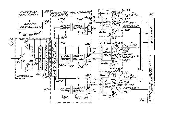
Referring now to FIG. 1, a block diagram of a
multifunction active array system embodying the invention
is disclosed. As will be understood by those skilled in
the art, the array comprises a plurality of radiative
elements 15, each coupled to a corresponding active module
20. For clarity only the "i"th element 15 and module 20
are shown in FIG. 1, where i is an index varying from 1 to
N, and N represents the total number of modules. Each of
the modules comprisin~ the array is identical to the
universal module 20 of FIG. 1.
Module 20 comprises a beam steering phase shifter 32
and a variable RF attenuator 28. These two devices may be
connected either to the transmit channel comprising
transmit amplifier 24 or to the receive channel comprising
low noise amplifier 26 by RF switch 30. RF switch 22
connects either the receive channel or the transmit
channel to the radiative element 15. The RF switches 22
and 30 are controlled by the array controller 94 to select
either the module transmit channel when an excitation
signal is provided to the module 20 or the module recei~e
channel when the module 20 is selected to provide an
amplified version of signals incident on the radiati~e
element 15. In operation, the RF switches 22 and 30 are
both either in the transmit "T" position or in the receive
"R" position. The ~unctions of these switches could
alternatively be accomplished by RF circulator devices,
well known to those skilled in the art.
The beam steering phase shifter 32 preferably is
digitally controlled by controller 94 , and introduces the
~297~
1 phase shift necessary to steer the aperture beam in the
~esired direction, as is well known to those skilled in
the axt.
The variable attenuator 28 is also controlled by the
array controller 94, and is used to weigh~ the aperture to
reduce the aperture sidelobe levels. The attenuator 28
can also be used for power management.
The array system ~urther compri~es N aperture
partitioning selectors 40, each coupled to selector port
1034 of a corresponding module 20. Each selector 40 com-
prises an M-way power divider/combiner device 42 having M
device ports, respectively coupled through a programmable
phase shifter and variable attenuator to a corresponding
one of the M RF switches. For the embodiment shown in
15FIG. 1, the index M is chosen as three, so that each
partitioning selector 40 comprises a three-way power
divider/combiner 42 with three device ports 42A, 42B, 42C,
three attenuators 45A, 45B, 45C, three phase shifters 43A,
43B, 43C, and three RF switches 44, 46, 48, all indepen-
20dently controllable by the array controller 94.
The array controller 94 preferably comprises a
digit,al computer which is interfaced to the various
elements it controls, ~uch as the various RF switches, the
variable attenuators and the beam stearing phase shifters.
25Each of the R~ switches 44, 46 and 48 provides the
capability of switching between an "off" position and an
"on" position. When ln the lloff'l position, each of the RF
switches 44, 46 and 4~ provides a matched load (not shown
in FIG. 1) to both the "on" and the "off" ports of the
30corresponding RF switch. The RF gwitches 44, 46 and 48,
therefore, provide a means for selectively connecting the
respective device ports 42A, 42B, 42C to a corresponding
partition port 46A, 46B, 46C of the selector 40. Each
partition port 46A, 46B, 46C iS connected to a correspond-
35ing one o the N selector ports 51Ai, 61Bi and 71Ci o~ the
~2g~97~
1 M manifold apparatus, in this embodiment the A, B or C
manifold apparatus 50, 60 or 70.
The output of each of the three RF switches 4~, ~6
48 at the respecti~e partition port 46A, ~6s, 46C is
summed at the corresponding manifold apparatus 53, 60 or
70 with the outputs from the corresponding RF switch of
each of the other aperture partitioning selectors 40 com-
prising the arxay system. Thus, as shown in FIG. 1, the
respective outputs Ai from the RF switches 44 are summed
at the "~" manifold apparatus 50, the respective outputs
Bi are summed at the "~" manifold apparatus 60, and the
outputs Ci from the RF switches 48 are summed at the "C"
manifold apparatus 70. If the index M were greater than
three, e.g., 5, then the selector 40 would include two
additional attenuators, phase shifters, and RF switches,
the divider/combiner ~2 would be a five-way device, and
there would be two additional manifold apparatus (not
shown), the "D" manifold apparatus and the "E" manifold
apparatus.
Z0 In the embodiment of FIG. 1, each of the manifold
apparatus 50, 60 and 70 comprises an N selector port by
two network port manifold network 52, 62, 72, and a magic
T coupler 57, 67, 77. The N selector ports of the respec-
tive manifold networks 52, 62, 72 are conneated to the
respective ~F switch ~ 6 or 4a of each partitioning
selector 40, and the two network ports are connected to
the sidearm ports of the respectlve magic T coupler 57, 67
or 77.
Each o~ the manifold networks 52, 62 and 72 are
typically constructed of two uniform corporate networks
such as are well known to those skilled in the art, acting
as uniformly weighted power combiner/divider circuits. In
the receive mode, the manifold networks 52, 62, 72 are
constructed to separately sum the signals at the firs~ N/2
selector ports and the signals at the latter N/2 selector
~2~ 9~
1 ports, and to provide the respective partial sums at the
respectlve X and Y network ports to be coupled to the
respective sidearm ports of the respective Magic T coupler
57, 67 or 77. For example, manifold network 52 is adapted
to sum the selector signals Ai, i=l to N/2, and to provide
the resulting partial sum at port 53X, and to sum the
signal Ai, i=N/2 ~1 to N, to provide the resulting and
partial sum at port 53Y. In the transmit mode, the
excitation signals applied at the respective X and Y ports
of the manifold networks 52, 62, 72 are each divided into
N/2 signals of equal amplitude and phase to be supplied to
the corresponding RF switches 44, 46, 48 of the respectivP
N/2 aperture partitioning selectors 40.
Magic T coupler devices 57, 67 and 77 are well known
in the art and are described, for exampled, in "Microwave
Antenna Theory and Design," edited by Samuel Silver, 1965,
1949, Dover Publications, at page 572. In the receiver
mode, the sum of the two partial sum signals at ports 53X
and 53Y, i.e., the sum of the signals Ai, i=l to N, will
appear at the sum port 57X of the Magic T coupler 57 with
the power at the difference port 56Y being essentially
zero. The respective sum ports 57X, 67X and 77X of the
Magic T couplers 57, 67 and 77 are then coupled to the
receiver 92 for signal processing. Each output at the
respective ports 57X, 67X and 77X represents the corre-
sponding array subaperture output resulting rom an
arbitrary partition o~ the array ormed by the positions
o the corresponding RF switches 44, 46 and 48.
The di~Eerence ports 57Y, 67Y and 77Y of the Magic T
couplers S7, 67 and 77 are connected to respective A, B
and C excitatiorl signal sources, in this case represented
by excitation ~requency synthesizer 90.
In the transmit mode, the excitation signal applied
at the difference port 57Y is divided into two signals, of
equal amplitude and phase, at the sidearm ports 56X and
12~7~
1 56Y, which are in turn divided by the manifold network 52
into N selector port excitation signals, oE equal ampli-
tude and phase, to be supplied to the corresponding RF
switches 44 of the respective aperture partitioning
selectors 40~ Similar functions are provided by the
manifold networks 62 and 72. The RF switches 44 select
the appropriate module for the excitation. For example,
an excitation signal "A" applied at port 57Y will be
divided into N equal power, equal phase signals to be
supplied to the RF switches 44 of the N aperture parti-
tioning selectors 40. For those modules to be employed in
the transmit mode for the A excitation signal, switch 44
will be set to the "on" position. The A signal component
may be combined with the B and C excitation signal compo-
nents, if RF switches 46 and 48 are also switched to the
"on" position.
The array system described with respect to FIG. 1
provides a means for arbitrary partitioning of the array
aperture formed by the N radiative elements lS comprising
the system. The three RF switches 44, 46 and 48 compris-
ing the aperture partitioning selector 40 provide arbit-
rary aperture partitioning on receive as well as on
transmit. The position of each switch determines the size
and configuration o~ each partition. On reception, the
position of each switch does not affect the outputs of the
other two switches; therefore, partitions can overlap
during this mode of operatlon. Since the array feed is
not divided into quadrants, full roll stabilization i9
realizable for any arbltrary partitioniny, as will be
described more fully below. On transmission, overlapping
partitions are also possible if the power amplifier 24 of
modules 20 is operated in the linear mode.
~5
37~
1 The provision of the beam steering phase shifters
43A-C and variable attenuators 45A-C in each channel of
the partition selector provides the capability o~ indepen-
dently s~eering or amplitude weighting fhe beam or pattern
formed by each sub-aperture. If these phase shifters and
variable attenuators are employed in the aperture parti-
tioning selector ~0, then the phase shi~ter 32 and vari-
able attenuator 2~ in the module 20 are unnecessary. The
phase shifters 43A-C and attenuators 45A-C could, of
course, be omitted from the selectors 40 i~ the flexibil-
ity provided by these elements is unnecessary; in this
case the module phase shifter 32 and attenuator 28 may be
employed to steer and shape the beam.
With the phase shifters ~3A-C, three independent
lS apertures may be formed with three independently steerable
beams, which on transmit may be excited by three indepen-
dent exciter signals generated by synthesizer 90. There
is another advantageous function which may be implemented
using the M exciter signals, to provide extended bandwidth
capability for off-broadside beams for very large aper-
tures. For such large apertures, the relatively large
spacing between the radiative elements lS on opposite
sides of the aperture can serve to destroy the additive
effects on signals from the spaced elements on an off-
zs broadside target for very short durakion impulse trans-
missions, i.e., having a wide bandwidth, so that the array
beams are eEectively limited to the broadside direction.
To correct Eor the diE~erences in range Erom the spaced
aperture elements to the target, the aperture may be
partitioned into M contiguou~ non-overlapping subaper-
tures, each driven by a delayed version of the same
excitation signal. Depending on the beam position, the
respective exciter signals are respectively delayed by
some predetermined time period needed to correct ~or the
range di~Eerence between the target and khe xadiative
1 elements 15 in the respective sub-apertures. Thus, if the
aperture is divided into subapertures A, B, C, with
aperture C closest to the target located in the off-broad-
side beam, then the exciter signal driving aperture A ,
the subaper~ure furthes~ from the target, will not be
delayed at all, the exciter signal driving ap~rture B will
be delayed by some period T, and the exciter signal
driving aperture C will be delayed by some period 2T, and
T being a function of the beam angle and the aperture
size. In a similar manner, the large-sized aperture may be
divided into three contiguous sub-apertures on receive, as
on transmit, and the summed components at ports 57X, 67X
and 77X, respectively, may be delayed by receiver 92 by
appropriate respective delays to correct for the range
difference between the respective subaperture radiative
elements and the off-broadside target.
Several specific examples of exemplary aperture
partitioning readily achievable by the system descrihed
with respect to FIG. l are now described.
Simultaneous Sum, Azimuth Difference and Elevation
Diffèrence Patterns
As is well known in the art, many radar systems
employ two or more displaced radiating/receive elements
(or groups oE elements) so that each receives the signal
from a point source at a sliyhtly different phase. The
received signals from each receive element (or group) are
summed to form the array sum signal, and the received
signal from one element (or group) is subtracked from the
signal recelved on the other element ~or group) to form a
difference signal. The diference signal is a measure of
the relative location o the target from the array bore-
sight, since the difference signal will be nulled iE the
boresight is perfectly aligned on the target.
DifEerence signals are typically provided with
respect to the azimuth and elevation null planes. Thus,
1~97~
1 the azimuth difference signal indicates the angular offset
of the ~oresight ~rom the target with respect to the
azimuth null plane, with the si~n of ~he signal indicatin~
the direction of the offset. Similarly, the magnitude and
si~n of the elevation difference signal indicates the
angular offset of the boresight from the target with
respect to the orthogonal elevation null plane.
The array system described with respect to FIG. 1
with the index M=3 can be employed to divide the array
system radiative array aperture into three or less sub-
apertures. FIG. 2 is a functional diagram for dividing an
exemplary circular aperture, i.e., where the N radiative
elements 15 are distributed throughout the area circum-
scribed by a circle, into fvur quadrants for generating
simultaneous sum, azimuth difference and azimuth elevation
signals. In this example, the radiative elements of the
array system are arranged in four quadrants I to IV,
defined by the azimuth null plane and the elevation null
plane.
To form the azimuth difference signalt the combined
contributions from the signals received by the radiatin~
elements quadrants II and IV are subtracted from the
combined signals received by the radiatiny elements in
quadrants I and III. The elevation difference signal is
provtded by subtracting the combined signals received at
the radiating elements in quadrants III and IV from the
combined signals received at the elements in quadrants I
and II. ~o confiyure the system to provide simultaneous
sum, difference azimuth and dierence elevation patterns,
the respective positions of the A, B and C RF switches 44,
46 and ~8 of the modules associated with radiative ele-
ments in the respective quadrants are shown in FIG, 2.
Thus, for those partition selectors 40 connected to
modules 20 connected to radiative elements 15 in quadrant
I, the A and C switches are positioned to the "off"
97~
1 position, and the B switches are positioned to the "on"
position. For the partition selectors 40 coupled to
modules 20 and radiative elements 15 in quadrant II, the A
switches are positioned to ths "on" position, and the B
and C switches are positioned to the "off" position. For
those partition selectors 40 associated with modules 20
and radiative elements 15 in quadrant III, the A switches
are positioned to the "off" position, and the switches B
and C are positioned to the "on" position. For those
partition selectors 40 associated with modules 20 and
radiative elements 15 in quadrant IV the A and C switches
are positioned to the "on" position, and the B switches
are positioned to the "off" position. The three manifold
apparatus outputs on reception are
~A = (Quad II) -~ (Quad IV)
~B = (Quad I) ~ ~Quad III)
~C = (Quad III) ~ (Quad IV)
from which
~ = (Quad I) -~ (Quad II) ~ (Quad III) -~ (Quad IV)
EA B
~AZ = [(Quad I) -~ (Quad III)] - [~Quad II)
(Quad IV)]
B A
~EL = [(Quad I) -~ (Quad II)] - [(Quad III)
(Quad IV)]
2 [(Quad III) -~ (Quad IV)]
= ~ - 2 ~c
= ~A + ~B -2 ~c
The invention provides a means of arbitrarily
assigning a particular radiating element to a particular
quadrant of the array without requiring changes in hard
wired connections or complex signal processing. The array
controller is provided with attitude position data, e.g.,
from the aircraft inertial platform 98 in the case of an
aircraft mounted active array. This data may be used to
direct the aperture partitioning selectors 40 to adjust
the respective module RF switches to the correct state for
the particular array roll angle.
This may be appreciated with reference to FIG. 3.
Assume that the array reference plane is initially aligned
with azimuth plane 210. The switch positions of the
aperture partitioning selectors 40 are as shown in FIG. 2.
Now assume that the array rolls to a 30 degree angle with
respect to the azimuth plane, such that the array refer-
ence planes are aligned with phantom lines 220 and 230
shown in FIG. 3~ To roll stabilize the array with the
horizon, the quadrant positions o~ certain of the radia-
tive elements 15 are reassigned. Thus, the radiative
elements 15 located in the croqs-hatched sector 222,
nominally in quadrant II for the case when the aircraft is
aligned with the horizon r are reassigned to quadrant I,
i.e., the roll stabllized or "new" quadrant I is the
former or "old" quadrant I minu~ the elements 15 in
cross-hatched sector 228 plus the element~ in cross-
hatched sector 222. Similarly, the radiative elements in
sector 22~l nominally in quadran~ IV, are reassigned to
quadrant II. The radiative elements in sector 226,
~Z~79~L
14
1 formerly in quadrant III, are reassigned to quadrant IV.
The radiative elements in sactor 228, formerly in quadrant
I, are reassigned to quadrant I.
To implement the reassiynment of radiative elements
re~uires only that the positions of the RF switches of the
apPrture partitioning selectors 40 associated with the
radiative elements 15 whose respective quadrant positions
are realigned be adjusted to conform to the states de-
scribed in FIG. 3 for the respective new quadrants. The
array controller 94 may effect this adjustment rapidly, so
that the azimuth and elevation difference patterns may be
electronically roll stabilized, without the need for
mechanical roll gimbals or complex signal processing.
The qystem of FIG. 1 provides a means for roll
stabilizing the aperture partitioning of the array with
respect to rotation of the array relative to a prede-
termined reference plane, such as plane 210 in FIG. 3.
The array may be assumed to have an array reference plane,
such as plane 230 in FIG. 3. The radiative-element-to-
sub-aperture connectionq for the initial or first roll
position state may be stored in memory by the array
controller. To compensate for rotation of the array to a
particular roll angle relative to the initial posi~ion
state, the array reference plane 230 is assumed to have
rotated by the particular roll angle relative to the
reference plane 210, and the po~itions of the radiative
elements (and as~ociated module 20 and aperture partition-
ing selector 40) relatlve to the reference plane associ-
ated with the initial pre-roll state are mapped into the
same corresponding positions relative to the new posltion
of the array reference plane.
797~
1 Adaptive Nulling
FIG. 4 shows a functional description of the posi-
tions of the RF switches of the aperture partitioning
selectors 40 to generate an auxiliary aperture for adap-
tive nulliny and simultaneous sum () and azimuth differ-
ence (~AZ) with a circular aperture. Alternatively, the
elevation difference pattern could be generated instead of
the azimuth difference pattern. Other combinations are
possible, e.g., a communication aperture with two aux-
iliary apertures. The three manifold apparatus outputsresulting from the configuration shown in FIG. 4 are
L = ~A
R = ~B
AUX = ~C
from which
A B
aAZ = ~A ~B
Auxiliary = ~C
Overlappin~ partitions
FIGS. 5A and 5B describe the positioning of the RF
switches of the aperture partitioning selectors 40 to
obtain two possible aperture partitions with overlap. As
illustrated by the two exemplary partitions in FIGS. 5A
and 5~, the three regions A, B, and C can take any arbi-
trary configuration. As will be appreciated by those
skilled in the art, the overlappi.ng apertures shown in
16
1 FIG. 5A may be necessary in some radar applications for
detection and location of slowly moving targets.
In the case illustrated in FIG. 5B, aperture A
comprises the entire area of the circular aperture of
radius rA, aperture B comprises the area within the
intermediate circle of radius rB, and aperture C comprises
the area within the inner sircle of radius rc. The
apertures are independent, and their beam may be scanned
and shaped (by the respective pairs of phase shifters and
attenuators comprising partitioning selector 40) indepen-
dently of each other. The three aperture outputs are
A = A
B = ~B
C = ~
C
One advantage of the embodiment shown in FIG. 1 is
that the aperture partition selector 40 may be located
outside the corresponding module 20, allowing the array
system to be implemented with N universal modules. The
additional elements needed to provide the increase in
aperture complexity are located outside the module. Since
not all applicatlons require the additional complexity,
the same modules 20 may be used or all applications. For
example, an active array antenna with roll stabilization
~or a two-way monopulse radar requires at least two
aperture~ (M = 2 or greater); on the other hand, a hal-
duplex communlcation system needs only a slngle aperture(M=l),
Higher order partitioning can be obtained by in-
creasing the number of oùtputs rom the apertùre parti-
tioning selector 40, i.e., increasing M. If a particular
partition is always limited to a certain physical area of
~2~9~7~
1 the aperture, then the corresponding manifold is required
to sum only those signals from manifolds lying in the
desired area. For example, if a guard aperture ~ormed by
four preselected radiative elements is required, then only
the corresponding four modul~ outputs need to be summed;
this will require only a four input manifold.
While the invention has been described with respect
to a circular array aperture, it may readily be practiced
with arrays having other configurations, e.g., rectangular
or trapezoidal.
A multifunction active array system has been de-
scribed which is capable of providing a number of useful
features. E'or example, the array system aperture can be
partitioned into M or fewer subapertures, which can
overlap. The aperture partitioning on transmit and on
receive can difer in any arbitrary manner. Each subaper-
ture can transmit and receive at different frequencies
and/or scan angles. For M=3 the array system can be used
to provide simultaneous sum, azimuth difference and
elevation difference patterns to provide a subaperture for
adaptive nulling, with simultaneous sum and azimuth (or
elevation) difference patterns or a simultaneous sum
pattern with a guard aperture. With the capability for
multiple independent transmit apertures, the system
further provide~ off-broadside expanded bandwidth capabil-
ities for large apertures. The system further provides
the capability for electronic roll stabili~ation for all
modes o operation.
The invention is not limited to active array sys-
tems, but may a~so be employed with passive array systemswhich do not employ active modules. In the case of a
passive array systeml the modules 20 shown in FIG. 1 are
eliminated, and the aperture partitioning selectors 40 are
connected directly to the respective radiative elements
~L29~79~L
18
1 15. Alternatively, the modules 20 could consist of only
the attenuator 28 and phase shifter 32. Arbitrary
aperture partitioning is available in this case as well~
It is understood that the above-described embodiment
is merely illustrative of the possible specific embodi-
ments which may represent principles of the present
invention. Other arrangements may be devised in accor-
dance with these principles by those skilled in the art
without departing from the scope o the invention.