Note: Descriptions are shown in the official language in which they were submitted.
lZ~ 15
CONTAINER FOR TRANSPORTING LONG OBJECTS,
ESPECIALLY ROLLS FOR PAPERMAKING MACHINES
Technical field of the invention
The present invention relates to a container
for transporting long, preferably cylindrical objects,
especially rolls for papermaking machines, comprising
on the one hand an outer supporting rigid metal frame
and, on the other hand, a nonsupporting casing protecting
th~ object.
Background of the invention
Large papermaking machines usually comprise a
number of big-sized and unwieldy rolls which must
be taken out of the machine at regular intervals and
sent away for maintenance. During transport, the rolls
must be adequately protected against damage from any
external violence. Up to now, specially made wooden
boxes have been used for protecting the rolls during
transport. However, the disadvantages of these wooden
boxes are considerable. They are expensive to manufac-
ture because high demands are placed on the stability
and strength of the box, int. al. because of the great
weight and length of the rolls. A further factor in-
creasillg the cost is that the box must give full pro-
tection to the roll surface. Wooden boxes of this
type must be regarded, in principle, as expandable
packings because they are usually destroyed when the
roll is unpacked. This means that the packaging cost
for each transport may be on the same order as or
higher than the actual transport cost of the roll.
Furthermore, a wooden box is not easily handled because
it may be difficult to attach the requisite lifting
lugs in a manner sufficiently reliable for the great
weight of the roll. It may also be difficult to insert
the forks of a fork-lift truck or the like underneath
the box.
~2~2~
-- 2
Summary of the Invention
A feature of one embodiment of the present invention
provides a container which is suitable for transporting
the rolls of papermaking machines or other long,
preferably cylindrical objects, and which may be reused
an indefinite number of times, which is easily handled
by, for example, a crane or fork-lift truck and which
simultaneously gives adequate protection to the contents.
In accordance with an embodiment of the present
invention there is provided a container for transporting
long objects, the container comprising an outer rigid
supporting frame and a nonsupporting casing adapted to
protect the objects to be transported, wherein the
supporting frame comprises a pair of end frame members
and a pair of side frame members connected to the end
frame members, the casing comprising a continuous bottom
member which is suspended in the. side frame members and
at least one top member detachably connected to the
bottom member, and wherein there are provided within the
casing at least two securing members secured to the side
frame members and adapted to secure the object to be
transported in a transport position.
In a preferred form, the casing may comprise both a
preferably semicylindrical continuous bottom part which
is suspended in the side frame members, and one or more,
preferably semicylindrical top parts detachably connected
to the bottom part, and there are provided within said
casing at least two clamping devices secured to said side
frame members and adapted to fix the object in transport
position.
3L2~3~32~
- 2a -
Further Illustration of Prior Art Techni~ue
US patent specification 4,615,453 discloses a
transport container of the type mentioned in the
introduction, i.e. a container which comprises both a
casing and a supporting frame therefor. In this case,
however, the casing is in the form of a tank which is
covered in all round and which under no circumstances can
be used for the storage and transport of long objects,
such as heavy rolls.
Brlef Description of the Accompanying Drawinqs
In the drawings
Fig. 1 is a side view of a transport container
according to the invention;
Fig. 2 is a longitudinal section of the container
shown in Fig. l;
~29l~;215
Fig. 3 is an end view of the container;
Fig. 4 is an enlarged section IV-IV in Fig. 2;
Fig. 5 is an exploded view of the container main parts;
Fig. 6 is a perspective view of the container as seen
obliquely from above; and
Fig. 7 is a perspective view of the container as seen
obliquely from below.
Detailed description of a preferred embodiment of
the invention
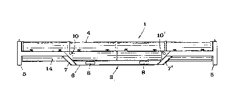
In the drawings, the transport container according
to the invention is designated l in its entirety.
Within the container; a roll 2 is indicated by dash-dot
lines. The container comprises an outer supporting
rigid metal frame generally designated 3. A casing
4 is arranged within the frame. The supporting frame
3 comprises two end frame members 5 located each at
one of the container short ends, and two side frame
members 6 arranged along each of the container long
sides and rigidly connected to said end frame members 5.
The end frame members are rectangular and made of
a hollow square section. Each side frame member 6
has two end parts 6' and a central part 6'' offset
in parallel relative to said end parts. The central
part 6'' is rigidly connected to the end parts 6'
by means of oblique connecting parts 7, 7'. The lower
edge of the end frame members 5 and the lower side
of the central parts 6'' of the side frame members
lie in a common plane and are located at such a distance
below the lower outer contour of the casing that a
space is formed underneath the casing for recesses
8 in each central part, said recesses being connected
in pairs with guides 9 in the form of rectar;gular
hollow sections or tubes for the fork arms of a fork-
lift truck or the like. The fork arm recesses 8 pre-
ferably are four in number and arranged in pairs sym-
metrically around the container center. Lifting lugs
lO, lO' are mounted on the oblique connecting parts
7, 7'. On the upper side of the rectangular end frames
5 (see Fig. 3), male members 11 are provided for co-
operatior wi-th corresponding female members 12 on
the lower sides of the end frames when several ccn-
tainers are stacked upon each other.
The casing 4 comprises a continuous semicylindrical
bottom part 14 composed of four corrugated standard
type sheet metal plates interconnected by welding
to semicircular horseshoe-shaped connecting members
13 located between the corrugated plates. The casing
top 15 comprises four loose cover portions 15', 15'',
15''' which also consist of corrugated standard type
sheet metal plates and have been given semicylindri-
form in that they have been welded at their ends to
semicircular horseshoe-shaped members 21, 22. Some
members 21 are provided along their upper edge with
a V-shaped fold to make them overlap and cover an
adjacent member 22. The ends Or the bottom part 14
are welded to circu'ar sheet metal discs 23 having
the same diameter as the outer diameter oE the horse-
shoe-shaped end members 22 and the connecting members
13. The cover portion 15' adjacent such a disc 23
also has a ~-shaped fold overlapping the disc 23.
Each longitudinal edge of a cover portion 15', 15'',
15''' has a pair of eyelets 19 cooperating with corre-
sponding eyelets on a longitudinal flange 24 secured
to each of the longitudinal edges of the bottom part
14. By means of these eyelets 18, 19, the cover por-
tions 15 can be connected to the bottom part 14 by
means of bolts 17 (see Fig. 5).
When the bolts 17 are removed on one side, the
eyelets 18 and 19, together with the bolts 17 on the
opposite side of the cover portion, will form hinges
so that the cover portion can be swung up in an optional
direction. The flange 24 also serves to secure the
casing to the end members 6' of the side frame member
by means of a number of bolts 20; see Figs. 5 and
6. In the area of the central part 6'' of the side
~Z~3~3215
frame member, the casing is, in principle, self-support-
ing, although it is possible to erlarge the connecting
member 13 outwardly so that it supports itself on
the central part 6''.
Within the casing, two clamping devices 25 are
mounted whose construction is best seen from Fig. 4.
These clamping de~-ices 25 are designed to hold a shaft
32 of the roll 2, as shown by dash-dot lines in Figs.
2 and 4. The flange 24 is so wide that it projects
a distance into the casing, and the projecting part
is used for fixing the clamping device 25. The clamping
device comprises a lower part 26 having a V-shaped
portion, and an upper part 27 having a portion in
the form of an inverted V, between which the shaft
journals 32 projecting from the roll ends can be firmly
clamped in position by means of bolts 28. The lower
part 26 of the clamping device is provided with wheels
29 mounted on projections 33 and resting on the bottom
part 14 of the casing 4 in the lowered position of
the clamping device. The lower part 26 of the clamping
device 25 overlaps the lower side of the flange 24
over a given distance. On the inner side of the flange
24, a bolt 30 is threaded into the lower part 26 on
both sides thereof near the inner edge of the flange
25 24. The bolt 30 extends through an abutment 31 over-
lapping the upper side of the flange 24. In the un-
tensioned state of the bolts 30, the lower part 26
is lowered into the container, such that the wheels
29 will engage the interior of the casing. At the
same time, the lower part 26, and thus the entire
clamping device, is of course released from the flange
24, which means that the clamping devices and the
roll clamped thereby can be displaced on the wheels
29 in the longitudinal direction of the container.
In this manner, the center of gravi~y of the roll
can be transferred to lie near the center of the con-
tainer. When the roll is in the desired position in
~9~215
the container, the bolts 30 are tensioned, and the
lower part 26 of the clamping device is raised into
engagement with the lower side of the flange 24 in
a raised position in which the wheels 29 are disen-
gaged from the inner side of the bottom part l4. Atthe same time, the clamping device will ~e fixed rela-
tive to the flange 24 and, thus, also relative to
the container in its entirety in that the inner edge
of the flange is clamped between the lower part 26
of the clamping device 25 and the clamping plate 31.
The outer frame 3 is preferably made of steel,
and the casing 4 of corrugated steel plate. The number
of the casing sections is four mainly because use
has been made cf corrugated standard sheet metal plates
of the type which is used for road culverts and normally
has a thickness of 2.6 mm and whose total length is
well in agreement with standard rolls for papermaking
machines. A wall thickness of 2.6 mm in the casing
is quite adequate for a satisfactory protection of
the roll surface, simultaneously as each of the four
cover portions is given a weight sufficiently low
to ensure ease of handling.
The transport container according to the inven-
tion has considerable advantages as compared with
prior art wooden boxes. The container may be reused
a practically unlimited number of times, which means
that the p~1ckaging costs for each transport will be
very low, even though the container is somewhat more
expensive than a corresponding wooden box. The outer
rigid and self-supporting frame can withstand heavy
stresses, especially upon loading and unloading of
the container with its contents, simultaneously as
the casing effectively protects the roll surface.
Furthermore, opening and unpacking of the container
is extremely simple, and at the same time the handling
of the container during loading and unloading, either
by crane or by fork-lift truck, is greatly simplified
~2~ 15
since the lifting eyes and guides for the fork arms
can be placed in convenient positions. It should be
pointed out in the context that the container can
be readily lifted by means of a fork-lift truck, even
if it should have been turned upside down upon un-
loading or loading since the entire weight of the
roll is transferred directly to the outer frame. Another
great advantage during handling is the possibility
of displacing the roll within the containers so that
its center of gravity will be in the most favourable
position relative to the position of the lifting eyes
or the fork arm guides. In view of the great weight
of the roll and the large extent of the container,
which in the embodiment illustrated amounts to about
seven meters, there is a risk that the fork-lift truck
may overturn if the roll is subjected to an eccentric
load.
Possible modifications of the invention
The invention may, of course, be modified in
various ways within the scope of the appended claims.
For example, the casing can be made completely or
partly of glass fiber-reinforced plastic or of sheet
metal laminated with foamed plastic. If the roll has
no protective layer when packed, the casing can be
lined with foamed plastic or wood, or similar material.
The bottom part of the casing may also be provided
with longitudinal tubes on the sheet metal surface,
serving as carriers for the wheels of the clamping
devices, which in that case will not be in direct
engagement with the sheet metal. Also, the casing
need not be cylindrical. The end frame members need
not be square; they may just as well be octagonal
or circular. The central part of the side frame members
may consist of several portions offset in parallel
both upwardly and downwardly, if desired, thereby
to lend better protection also to the casing top.
The frame may, of course, have several side frame
12~2~5
members on both sides. The fork recesses in the frame
may be designed differently and located in other posi-
tions than those illustrated in the preferred embodi-
ment. The clamping devices are shown to directly support
a roll shaft, but may of course comprise a suitably
removable part directly adapted to the shaft diameter.
In the event that the shaft bearings stay on the roll
taken out of the machine, the clamping devices are
preferably used to hold the bearings. Furthermore,
the clamping devices may act directly upon the roll
if the shaft does not go with the removed roll, or
if the roll does not have a shaft. The connecting
parts 7, 7' need, of course, not to be oblique but
can be arranged at right angles to the remaining parts
of the side frame members, or in some other suitable
manner. It is also possible to use the container for
long objects other than rolls for papermaking machines,
for example rolls of printing machines or other vul-
nerable objects. It is also possible to use other
devices for fixing the shaft within the casing than
the type of clamping devices exemplified in the
drawings.