Note: Descriptions are shown in the official language in which they were submitted.
1;~9~;~5~i
Warning Li~ht Device
The invention relates to a warning light
device having a directional warning panel to
regulate traffic, which is attached in a vertical
position in the vicinity of the back of a vehicle
and on which traffic symbols for following traffic
can be displayed by means of controllable electrical
luminous elements.
A warning light device of this type is known
from German Patent 34 34 341 issued on April 3, 1986
to Kupper. This known warning light device has a
vertical panel with colored stripes and electric
lights mounted on it in the form of an arrow. A
standard traffic symbol is also fastened to the
lower part of the panel. The lights are secured on
a rotatably supported, arrow-shaped holder, so that
the arrow can be adjusted to point downward to the
left or downward to the right. The vehicle is
embodied as a trailer and can be hitched to a motor
vehicle that can then take on the task of supplying
power and control to the warning light device. As a
rule, such warning devices are set up at
construction sites and are supplied electrically
directly from the a.c. grid via installed current
supply cables.
However, these known warning light devices
are limited to displaying the traffic symbol firmly
attached to them, along with the adjustable
illuminated arrow pointing to the right or left.
Moreover, such warning light devices unsuited to
accompanying a heavy-load truck or the like, because
the traffic symbol cannot be discerned by drivers in
~- ~z9~
moving traffic until just before they arrive at the
warning light device.
It is the object of the present invention to
improve a warning light device of the type referred
to above such that it can be used as an accompanying
vehicle for a heavy~load truck or
- 2a -
",
the like, the displayed traffic symbols are more accurately
discernable to following traffic, and the variety of display
possible is substantially greater.
According to the invention, this object is attained in that
the warning panel is embodied as a controllable optical fiber
display matrix having a plurality of traffic symbols and is
attached or attachable to the roof, extending continuously as far
as the back, of a motor vehicle; that it is supplied or
suppliable by the electric power supply system of the motor
vehicle or a supplementary electric power pack accommodated in
the motor vehicle; that an operating panel is disposed in the
vicinity of the dashboard of the motor vehicle, or is built into
the dashboard, which panel has operating elements for switching
the warning light device on and off and for initiating the
displays of various traffic symbols on the optical fiber display
matrix; and that the operating panel, the power supply and the
optical fiber display matrix are connected or connectable to one
another via connecting cables installed within the motor vehicle.
The warning light device is itself embodied as a motor
vehicle and can therefore easily follow any heavy-load truck.
The traffic symbols displayed are located at a great distance
from the road surface, so that even in a long line of vehicles
they can be readily seen from vehicles farther away. All the
controls and the electrical power supply are integrated in the
motor vehicle, making the warning light device an autonomous,
mobile unit that is ready for use at any time. The use of an
optical fiber display matrix makes it possible in the simplest
way to display a plurality of accurately represented traffic
symbols, such as arrows to indicate the direction of travel,
speed limit signs, and the like, which can be adapted to the
traffic situation at any time, even en route, by the driver of
the motor vehicle. All that is needed are suitable control
~2g~
signals, which can easily be provided by the operating panel
disposed or installed in the vicinity of the dashboard.
The display of various traffic symbols on the warning panel
is attained simply by providing that the optical fiber display
matrix has a plurality of optical fiber bundles, which can be
illuminated via individually triggerable light sources, and that
the free ends of the individual optical fibers of the optical
fiber bundles in the vicinity of the optical fiber display matrix
termi~ate in the position assigned to various traffic symbols.
The structural design of the optical fiber display matrix
is selected in one embodiment such that the optical fiber display
matrix comprises a breadboard with light-emitting pixels, which
are each connectable to one end of an optical fiber; that the
optical fibers that are assigned to a traffic symbol or to one
color of the traffic symbol are joined into an optical fiber
bundle which can be illuminated individually; and that the
optical fiber bundles are assigned individual light sources
and/or color filters.
If it is further provided that the optical fiber display
matrix is accommodated in a housing, which is pivotably connected
transversely to the vehicle axis onto a rooftop stand
construction connectable to the motor vehicle and can be folded
toward the front of the vehicle down onto the roof, then it is
extremely simple to put the optical fiber display matrix into a
storage position, in which the display can no longer be seen.
For optical reasons and reasons of wind resistance, a
pivotably attached spoiler that covers the optical fiber display
matrix folded onto the roof both in the working position and in
the folded-down position is also provided, with its cross section
decreasing toward the front of the vehicle.
If the motor is to be used especially as an accompanying
vehicle, then an embodiment that is characterized in that the
lZ9~S~i
optical fiber display matrix, the rooftop stand construction and
the spoiler are firmly attached to the motor vehicle, and that
the connecting l~ads are permanentl~ installed in the motor
vehicle and are hardwired is advantageous.
The invention will be described in detail in terms of
exemplary embodiments shown in the drawings. Shown are:
Fig. 1, in a perspective side view, a warning light device
embodied as a motor vehicle;
Fig. 2, the motor vehicle shown in Fig. 1 in a different
perspective side view;
Fig. 3, a breadboard having two optical fiber bundles and
two light sources for displaying two different traffic symbols;
Fig. 4, a breadboard having two optical fiber bundles and
two light sources for displaying a two-colored traffic symbol;
Fig. 5, a portion of a columnar lighting fixture, seen from
behind;
Fig. 6, a side view in the direction of the arrow IV of
Fig. 5;
Fig. 7, a section taken along the line A-A of Fig. 5;
Fig. 8, a further warning light device with a rooftop stand
construction, seen in a perspective side view;
Figs. 9 and 10, a motor vehicle in two different
perspective side views of the warning light device of Fig. 8; and
Figs. 11 and 12, the motor vehicle shown in Figs. 9 and 10,
with the warning light device in the storage position.
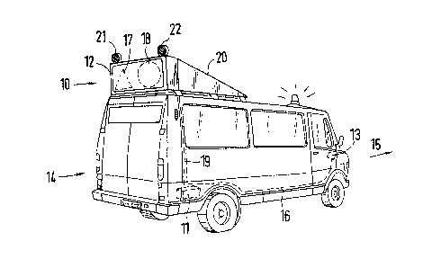
In Figs. 1 and 2, a warning light device 10 having an
optical fiber display matrix 12 is shown as a means of regulating
traffic.
The optical fiber display matrix 12 is disposed in a
vertical position on the back of a motor vehicle 14 traveling in
the direction of travel 15 and can display traffic symbols 17 and
18 for the following traffic by means of controllable luminous
5 --
elements. The warning light device 10 is accommodated in a
housing 20, on the upper and horizontally extending edge of which
two further signal devices 21 and 22 are disposed.
As Figs. 3 and 4 show, the optical fiber display matrix 12
comprises a breadboard 25 (in this case a matrix) with light-
emitting pixels 27 and 28, in which one set of ends of optical
fibers 29-32 is disposed. The other ends of the optical fibers
29-32 are illuminated by light sources 40-43 (in this case
halogen lamps). Optical fibers 29 and 30, which are assigned to
one traffic symbol in the breadboard 25, are each joined together
into a multi-armed optical fiber bundle 50 and 51. The light
sources 40 and 41 are each located in a concave mirror 54 and 55,
respectively, so that the emitted light directly strikes the ends
57 and 58 of the optical fiber bundles 50 and 51. Fig. 3 shows
that a light filter 60 is disposed between the light source 40
and the end 57 of the optical fiber bundle 50.
Fig. 4 shows that the symbol (in this case the numeral 6)
shown on the br~adboard comprises groups of pairs 62, 63 of
pixels, such that one pixel of each of the groups of pairs 62 and
63 belongs to the first optical fiber bundle 70, while the other
pixel of the groups of pairs 62 and 63 belongs to the second
optical fiber bundle 71. The two free ends 74 and 75 of the
optical fiber bundles 70 and 71 are illuminated by the light
sources 42 and 43. In this exemplary embodiment, the two free
ends 74 and 75 of the optical fiber bundles 70 and 71 are
connected to a lighting unit 80, which comprises the two light
sources 42 and 43.
As Figs. 5, 6 and 7 show, the lighting unit 80 comprises a
housing in the interior of which two concave mirrors 81 and 82
are disposed, and which is provided with connection fixtures 84
and 85 for the optical fiber bundles not shown in further detail.
The concave mirror 81 is disposed coaxially with the
-- 6
~z~
connection fixture 84, while the concave mirror 82 extends
coaxially with the connection fixture 85. The axes 87 and 88 of
the concave mirrors 81 and 82, respectively, define a common
plane and intersect at an angle of 9o. It can be seen that the
light source 90 is a point souxce, which is disposed in the focal
point of the concave mirror 81 or 82, respectively.
A semitransparent mirror 96 is disposed in the vicinity of
the point 94 of intersection of the axes 87 and 88 and is
disposed at a ri~ht angle to the plane defined by the two axes 87
and 88 and is intersected by the axes 87 and 88 at an anyle of
45. 50% of the light stream of the two point light sources
passes through the semitransparent mirror 96 to reach the entry
faces 74 and 75 of the optical fiber bundles, not shown in
further detail, that form the symbol. If one point light source
fails, the other point light source 90 is switched on, and in the
same way illuminates the two opti.cal fiber bundles 70 and 71.
The display can be made multi-colored, by placing a suitable
color filter before the entry face of one of the two optical
fiber bundles 74 and 75. If especially high luminous intensities
are required, for instance in fog, then the brightness of the
symbol can be doubled by switching both point liqht sources on
simultaneously.
The lighting unit 80, as it is shown in Figs. 5, 6 and 7,
can be combined to make a columnar lighting fixture, which is
then accommodated in the housing 20. Figs. 5, 6 and 7 also show
that the point light sources 90 are disposed in sockets 100 and
are retained by prestressed spring elements 102. The spring
elements 102 are connected by means of rivets 103 to the lighting
unit 80.
Fig. 3 shows that the ends of the optical fibers 29 and 39
in the breadboard 25 are disposed such that a two-colored traffic
symbol, or two different traffic symbols, can be displayed (see
~9~ i6
also Fig. 2). The ends of the optical fibers 29, 30 and 31 and
32 terminating in the breadboard 25 widen conically toward their
ends and are disposed counter sunk in the individual holes in the
breadboard 25. The pixels 27 and 28 have a diameter of
approximately 4 mm. In the breadboard 25, the optical fibers 29,
30 and 31, 32, respectively, are connected by means of spreader
sleeves, not shown in detail. For a two-colored traffic symbol,
the optical fibers 29 and 30 can be distributed over the entire
breadboard 25, while for two different traffic symbols the
optical fibers 29 and 30 are distributed over separate regions of
the breadboard 25.
The lighting units shown in Figs. 5, 6 and 7 are connected
to the housing 20 in a vibration-free manner and are connected to
the interior of the motor vehicle via electrical connecting leads
16 and 19. From there, the lighting units or columnar li~hting
fixtures can be controlled, specifically via the operating panel
13 that can be built into the dashboard. Power supply can be
effected via the electrical power supply system 11 of the motor
vehicle 14 or by an additional power supply or power pack, which
is also accommodated in the motor vehicle 14. The connecting
leads 16 and 19 connect the operating panel 13, the power supply
system 11 and the optical fiber display matrix 12 to one another.
The optical fiber display matrix 12 can be permanently connected
to the motor vehicle 14, and the connecting leads 16 and 19 can
also be permanently installed in the motor vehicle 14 and
connected (Fig. 2).
Naturally it would also be possible to equip all the pixels
27 and 28 of the breadboard 25 with optical fibers and to join
the other ends in such a way that they are illuminated by the
same point light source simultaneously. If a filter having a
certain shape and property is then placed between the point light
source and the free ends, certain ends of the optical fibers will
129~
not be illuminated, and so only some of the optical fibers will
carry light to the breadboard. This has the advantage that the
desired traffic symbol can be displaved by means of the selection
of certain filters. Naturally, a light source of suitable
capacity is then required.
In Fig. 8, a warning light device 200 embodied as a
variable-message traffic sign is shown, which is disposed in a
holder 202 and is supported by a rooftop stand construction
comprising struts 190, 191 and 210-213. This rooftop stand
construction can be detachably connected to the roof of the motor
vehicle. The warning light device 200 is joined to a spoiler
214. Both the spoiler 214 and the warning light device 200 are
connected pivotably about the pivot shaft 217 and 220 to the
rooftop stand construction.
The pivot shaft 220 is embodied such that the warning light
device 200 is displaceable transversely to the direction of
travel of the motor vehicle 14 and can be locked in place. The
spoiler 214 has an approximately plane segment 216, which merges
with a curved segment 215. The free ends of the struts 190 and
191 are connected via pivots 204 and 205 to a plate 203 having
perforations. This plate at least partly covers the back of the
vehicle (see Figs. 10 and 12). The segment 206 of the warning
light device displaying the traffic symbol is embodied, in terms
of its light output, similarly to or identically to the optical
fiber display matrix 12 shown in Figs. 3 and 4.
In the vicinity of the support posts 223, the spoiler 214
can be folded down about the pivot shaft 217.
In Figs. 9 and 10, the warning light device shown in Fig. 8
is shown in the working position. For stabilization and to
adjust the angle of the warning light device 200, an adjusting
post 222 is provided, one end of which is pivotably connected to
the rooftop stand construction, while its other end is adjustable
in a vertically extending groove 221 that is embodied on the back
of the warning light device 200.
Finally, Figs. 11 and 12 show the warning light device 200
in the storage position. It rests with its back on the rooftop
stand construction and is covered by the spoiler 214. A control
motor, not shown, is provided for extending and retracting the
warning light device 200, so that all operation can be done from
the driver's cab of the motor vehicle 14 via the operating panel
13 built into the dashboard.
-- 10 --