Note: Descriptions are shown in the official language in which they were submitted.
~2982~7
NOZZLE ASSEMBLY FO~ ROTARY DRILL BIT
AND METHOD O~ INSTALI~TION
Backqround of the Invention
This invention relates to a nozzle assembly for a rotary
drill bit and method of installation, and more particularly to
such a nozæle assembly and method in which the nozzle assembly
has a port oriented for discharging drilling fluid in a
predetermined rotational position with respect to the
longitudinal axis of the nozzle assembly.
Heretofore, much as shown in U.S. Pat. No. 4,533,005
dated August 6, 1985, nozzle assemblies have been provided in
which an inner nozzle member could be rotated relative to an
outer securing ring or sleeve threaded within an internally
threaded nozzle bore in the bit body for properly orienting
the port in the nozzle member. However, the inner nozzle
member for such externally threaded nozzle assemblies has
rotated with the nozzle assembly during insertion or instal-
lation of the nozzle assembly within the nozzle bore. Then,
after the initial installation, the nozzle member is rotated
relative to the outer retaining sleeve or nut for proper
orientation. In the event the nozzle member is not tightly
secured, and particularly after long periods of use, the
nozzle member may rotate and thus result in a disorientation
of the deviated port.
In aforesaid U.S. Pat. No. 4,533,005 the nozzle member is
held against rotation primarily by the compression of an
adjacent O-ring. Such an arrangement, when the nozzle port is
deviated at a relatively large angle and utilized with a high
velocity drilling fluid may result in a disorientation of the
nozzle port, particularly upon vibrations resulting from the
~X9~277
drilling operation after prolonged periods of use and compres-
sion set of the O-ring.
Summary of the Invention
The present invention is directed particularly to a
nozzle assembly for a rotary drill bit and method of installa-
tion, and particularly to a nozzle assembly which is received
within a nozzle bore in the bit body for receiving pressurized
drilling fluid being directed against a formation in the cut-
ting operation.
The improved nozzle assembly includes a nozzle member
having a nozzle port therethrough oriented at a predetermined
rotational position for installation against a counterbore in
the nozzle bore. A separate retaining nut receiving the
nozzle member has external screw threads for engaging internal
screw threads of the bore for being threaded within the bore in
a tight fitting relation therein. The retaining nut and nozzle
member have opposed facing abutting shoulders and upon the
inward threading of the retaining nut, the nozzle member urges
the contacting opposed shoulders into a tight secured position
in the bore against the counterbore thereof. During such
rotation of the retaining or lock nut into tight fitting
relation, the nozzle member is held against rotation with its
port in a predetermined oriented position for directing the
flow of drilling fluid from the port in a predetermined pattern
or direction.
Thus, upon the retaining nut being threaded into its
final tight fitting relation within the nozzle bore, the
nozzle member and associated nozzle port are in a tight
secured position and do not require any further orientation.
Even with high velocity drilling fluid being discharged
1298277
through the nozzle port, the nozzle member comprising the
present invention remains tightly secured and does not tend to
rotate from its secured position. To prevent rotation of the
nozzle member during the threading of the retaining nut within
the nozzle bore, the nozzle member includes means to receive a
tool or t~le like for preventing such rotation, Such means to
prevent the rotation of the nozzle member during insertion of
the retaining nut may comprise a positioning groove or projec-
tion within the bore or suitable openings or the like in the
nozzle member to receive a tool.
It i5 an object of this invention to provide a nozzle
assembly for a rotary drill bit and method of installation in
which the nozzle assembly has an oriented port for discharging
drilling fluid rom a predetermined rotational position with
respect to the longitudinal axis of the nozzle assembly.
An additional object of th.is invention is to provide such
a nozzle assembly and method of installation in which the
nozzle member having the oriented port therein is held against
rotation during installation of the nozzle assembly into tight
fitting relation.
An additional object of the invention is to provide such
an improved nozzle assembly in which an externally threaded
retaining nut receives the nozzle member and engages internal
screw threads in the nozzle bore for installation of the
nozzle assembly upon rotation of the retaining nut relative to
the nozzle member while urging the nozzle member into a tight
fitting relation within the adjacent bore during installation
of the nozzle assembly.
Other objects, features, and advantages of this invention
will become more apparent after referring to the following
specification and drawings.
~982~7
crl~ti~L af tl~a ~ra~inq~
Figure 1 is a elevation of a drag type rotary drill bit
with a portion broken away and illustrating a nozzle assembly
comprising the present invention within a nozzle bore in the
bit body;
Figure 2 is an enlarged fragment of Figure 1 showing the
improved nozzle assembly in section positioned within the
nozzle bore of the bit body;
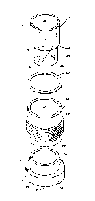
Figure 3 is an exploded view of the nozzle assembly shown
in Figure 2 illustrating the elements of the nozzle assembly
removed from the bore opening;
Figure 4 is a sectional view similar to Figure 2 but
illustrating installation tools engaging the nozzle assembly
for installation thereof into a tight secured position within
the nozzle bore while the nozzle member is held against
rotation;
Figure 5 is a bottom plan of a nozzle assembly showing
the openings for receiving extending prongs on the installa-
tion tools shown in Figure 4;
Figure 6 is a perspective of a spanner wrench having a
pair of prongs thereon and forming the tool for rotating the
nozzle assembly;
Figure 7 is a perspective of the other tool engaging the
inner nozzle member of the nozzle assembly to hold the nozzle
member against rotation as the nozzle assembly is being
threaded within the nozzle bore;
Figure 8 is a sectional view of a modified nozzle assem-
bly adapted to be installed with a single installation tool;
and
Figure 9 is a sectional view of the embodiment shown in
Figure ~ but showing the installation tool rotating the
1298Z77
retaining nut relative to the nozzle member for installing the
nozzle assembly.
Referring now to the drawings and more particularly to
Figure 1, a rotary drill bit of the so-called drag drill bit
type is shown generally at 10 connected to the end of a drill
string at 12. Drill bit 10 has a bit body 14 with a plurality
of cutting elements shown at 16 extending from the outer face
of bit body 14. Cutting elements 16 may be provided with
diamond cutting faces mounted on studs which are received
within suitable openings in bit body 14 as well known.
Drilling fluid is provided from a surface location through a
central main flow passage shown at 18 and a plurality of branch
flow passages 20 communicating with main passaqe 18. Each
branch flow passage 20 terminates at a nozzle bore generally
indicated at 22 in bit body 14.
A nozzle assembly qenerally indicated at 24 is positioned
within nozzle bore 22. Figures 2-5 show a preferr~d embodiment
of nozzle assembly 24 while Figures 6 and 7 show tools for
installing nozzle assembly 24 of Figures 2-5 within nozzle bore
22. Nozzle bore 22 includes an inner small diameter coun-
terbore 26, an intermediate counterbore 28 having internal
screw threads 29, and a large diameter outer counterbore 30.
Nozzle assembly 24 includes a nozzle member generally
designated 34 formed of a hard metal such as tungsten carbide
with abrasion resistance to the high velocity drilling fluids.
Nozzle member 34 includes an inner large diameter bore portion
36 leading to an outer small diameter bore portion 38 having a
port or orifice 40 deviated from the longitudinal axis of
nozzle member 34. An outer annular shoulder or abutment 44 is
provided adjacent a reduced diameter outer end portion 46 of
nozzle member 34. End portion 46 has an outer face 48 with an
~;~9~3277
opening 50 therein to receive a suitable tool as will be
explained further. An O-ring 52 seals between the outer
peripheral surface of nozzle member 34 and the adjacent surface
of bit body 14 defining bore 22.
A retaining lock nut is generally indicated at 54 and
includes an externally threaded sleeve 56 having external
screw threads 57 for engaging internal threads 29 of inter-
mediate counterbore 28 and defining a central bore 58 receiv-
ing nozzle member 34. Nut 54 further includes an outer
generally cylindrical body 60 with an inner end portion 62
fitting within sleeve 56 and forming a radially extending
internal or inner shoulder 64 for abutting contact with
adjacent shoulder 44 on nozzle member 34. Body 60 is brazed or
bonded to outer sleeve 56 and forms with sleeve 56 a one piece
construction for retaining nut 54. Cylindrical body 60 has an
outer flange 65 having a plurality of openings 66 therein
adapted to receive a suitable tool as will be explained. While
body 60 is normally formed of a hard carbide material, it may,
lf desired, be formed of the same material as sleeve 56 which
lS normally steel.
Referring now to Figure 6, an installation tool is shbwn
at 68 in the form of a spanner wrench including an annular
body 70 having a pair of prongs 72 extending therefrom and
defining a central opening 74. Prongs 72 are adapted to fit
within an opposed pair of openings 66 of retaining nut 54 for
manual rotation of retaining nut 54. In order to hold nozzle
member 34 against rotation with retaining nut 54 during final
assembly after orientation, a second tool is shown in Figure 7
indicated generally at 76 including a relatively flat body
portion 78 having a pair of prongs 80 and 82 projecting
therefrom. Prong 80 is adapted for fitting within opening 50
~;~9827~
ln no~le memb~ 34 ~hile pron~ 87. is adapted for fittin~
w~th~n port 40 of no~z~e member 34, Further, a removable
alignment prong or marker 83 secured by ~set screw 85 is
provided for holding tool 76 and port 40 in the oriented
position during installation of nozzle assembly 24. Suitable
spaced markings or openings 84 may be provided for alignment
with prong 83 at a desired orientation of port 40. Alignment
marker 83 may be removed to permit tool 68 to be rotated past
three hundred sixty (360) degrees.
In operation when tools 68 and 76 are utilized for
installation of nozzle assembly 24, nozzle member 34 is
received within retaininq nut 54 and in this position nozzle
assembly 24 is manually po.sitioned within no%%le bore 22 until
the external screw threads 57 on sleeve 56 contact the internal
screw threads 29 in bore 22. Next, tool 68 is utilized and
prongs 72 are inserted withi.n openinqs 66 of retaining nut 54.
Then, tool 76 is utilized with prongs 80 and 82 being
positionecl within openinq 74 o~ tool 68. Then, prong 80 is
inserted within openi.ng 50 and prong 82 is inserted within port
4n as shown in ~'igure 4. In this position, nozzle member 34 is
held against rotation by tool 76 while retaining nut 24 is
manually rotated by tool 68.
Thus, nozzle member 34 ~oes not tend to rotate even though
--7--
129~327~i)
i~wc~ ~ora portlon 3~ an~ port 40 deviate from the longitudi-
nal axis of nozzle member 34 and are exposed to high velocity
drilling fluids for prolonged periods of time. Retaining ring
54 as well as nozzle member 24 are preferably formed of a
suitable abrasion and erosion resistant material, such as a
tungsten carbide with a cobalt binder. Threaded sleeve 56,
may be formed of a machinable metal such as steel which may be
secured to body member 60 by brazing. Body member 60 may
likewise be formed preferably of an abrasion or erosion
resistant material, such as tungsten carbide.
Referring now to Figures 8 and 9, a modified nozzle
assembly 24A is illustrated which is particularly adaptable
for being installed within a nozzle bore 22A by a single tool
shown at 68A. Nozzle bore 22A defines an inner small diameter
counterbore 26A, an intermediate counterbore 28A and a large
diameter outer counterbore 30A. Inner counterbore 26A includes
a plurality of 51Ots or indentations 86 circumferentially
spaced from each other at fifteen (15) degree intervals, for
example. The inner circumferential surface of nozzle member
34A adjacent large diameter bore portion 36A includes a
plurality of nibs or lips 87 spaced about the circumference of
nozzle member 34A at fifteen (15) degree intervals, for
example, and adapted to fit within cooperating slots or
indentations 86 of counterbore 26A. Nozzle assembly 24A
includes a nozzle member 34A having an abutting shoulder 4qA
and a lower bore portion 38A leading to an outer port 40A
deviated from the longitudinal axis of nozzle member 34A.
Retaining ring or nut 54A has a sleeve 56A secured to an outer
body 60A which defines an abutting shoulder 64A in contact with
shoulder 44A on nozzle member 34A. Outer body 60A has a pair
of opposed openings 66A therein. A plastic insert 88 having an
lZ~8277
exten~ion 89 ls adapted to be positioned within port 40A to
protect port 40A during installation of nozzle assembly 24A.
An installation tool 68A has a pair of prongs 72A with a
depressible plunger member 90 therebetween urged outwardly by a
spring 92.
For installation of nozzle assembly 24A, prongs 72A of
tool 68A are positioned within openings 66A of outer retaining
nut 54A after plastic insert 88 is positioned adjacent the
outer face 48A of nozzle member 34A and extension 89 is
received within port 40A and bore portion 38A. Plunger 90
engages insert 88 and is urged outwardly by spring 92 for
urging nozzle member 34A inwardly where nibs or lips 87 are
received within associated slots 86 in bore 22A. Cooperating
nibs 87 and slots 86 prevent rotation of nozzle member 34A
during rotation of retaining ring S4A by tool 68A and plunger
90 maintains nibs 87 in such slots 32A. Thus abutting shoul-
ders 44A and 64A are normally spaced during the initial
installation of nozzle assembly 24A. However, during the last
several turns of sleeve 56A, shoulder 64A contacts shoulder 44A
and urges nozzle member 34A into tight seated engagement within
bore 22A. Thus, a single tool 68A is provided which rotates
retaining ring 54A while preventing nozzle member 34A from
being rotated therewith. Thus, port 40A can be oriented in the
desired direction for the drilling fluid upon the initial
installation of nozzle assembly 24A. Insert 88 protects port
40A and bore portion 38A during the installation operation
since plunger 90 tends to rotate with the rotation of tool
68A. Insert 88 may be formed by many desired materials, such
as a hard plastic material, for example.
From the foregoing, it is apparent that an improved
nozzle assembly has been provided by the present invention
1298277
pormltting nozzle members having a deviated nozzle port to be
initially oriented at the beginniny of the installation
operation so that upon the completion of the threading of a
retaining or locking nut, the nozzle member associated deviated
port are in the desired oriented position tightly fitting
within a nozzle bore without any further installation or
orienting steps required.
While preferred embodiments of the present invention have
been illustrated in detail, it is apparent that modifications
and adaptations of the preferred embodiments will occur to
those skilled in the art. However, it is to be expressly
understood that such modifications and adaptations are within
the spirit and scope of the present invention as set forth in
the following claims.
--10--