Note: Descriptions are shown in the official language in which they were submitted.
- 129~3347
THIS INVENTION relates to an electrochemical cell. ~lore particularly
the invention relates to a rechargeable high temperature
electrochemical power storage cell of the type having a molten alkali
metal anode separated from a cathode by a separator.
According to the invention there is provided a rechargeable high
temperature electrochemical power storage cell having a molten al~ali
metal anode separated from a cathode by a separator, the separator
dividing the cell into an anode compartment which contains said alXali
metal and a cathode compartment which contains a cathode, and the
separator penmitting the anode alXali metal to pass therethrough during
discharge of the cell from the anode compartment to the cathode
cc)mpartment into which it is released in ionic form for reaction with
the cathode, the cell having an opeTative attitude in which it is
upright, in which operative attitude the separator extends at an angle
to the horizontal so that the level of the surface of anode metal in
the anode compartment to which the separator is exposed, drops during
discharge of the cell and rises during charging of the cell, the anode
compartment having a lower portion and an upper portion which has a
greater horizontal cross-section than the horizontal cross-section of
the lc)wer portion, and the lower portion being entirely filled with
anode.~.etal in the fully discharged state of the cell.
The separator may be a solid electrolyte conductor of ions of the anode
.metal, the separator being in the form of a cylindrical tube which is
closed at one end.and open at the other and has a hollow interior, the
separator tube being arranged in the interior of a cell.housing so
that, in said operative attitude of the cell, the closed end of the
tube is lowermost and the open end of the tube is uppermost, the
~298347
interior of the tube forming an electrode compartment and the tube
being spaced from the housing so that a space is defined between the
tube and the housing which forms another electrode compartment. In
this type of construction, when the anode compartment is in the
interior of the tube, it will normally be of circular or annular
cross-section, and when it is outside the tube, it will normally be of
annular cross-section. For the horizontal annular cross-section of the
lower portion of the anode compartment to be less than that of the
upper portion, it follows that, in this type of cell, the lower portion
will have a smaller horizontal, eg radial, dimension than that of the
upper portion. Thus, when the anode compartment is annular, the
amlulus of the upper portion will be thicker than that of the lower
portion.
As the separator tube will usually (because of the way in which such
tubes are typically made) be of constant diameter, different horizontal
cross-sections for said upper and lower portions may be provided by
having the casing circular in cross-section and by having the casing
change in diameter (when the anode compartment is outside the tube);,or
by placing an insert in the lower portion of the anode compartment (eg
a tubular insert when the anode compartment is outside the tube, or a
cylindrical or tubular insert when the anode compartment is inside the
tube), with the insert concentric with the tube and radially spaced
therefrom. Instead, the insert may be in powder or granular form.
In a particular embodiment, the separator tube may accordingly have a
constant diameter, the interior of the tube forming the cathode
compartment, the housing being of circular cross-section, and the tube
being arranged concentrically therein and the space between the tube
and housing forming an annular anode compartment.
When the anode compartment is annular in horizontal cross-section, the
thickness of the annulus is preferably as low as practicable, eg about
0,1 - 0,2 mm for practical purposes. Similarly, the lower portion of
the anode compartment should have an upper end which is as high as
practicable, and the ~ower portion should extend upwardly to an upper
end which is at least as high as the midpoint of the separator in a
vertical direction. Accordingly, in a particular embodiment of the
1298347
invention, the thickness of the lower portion of the annulus of the
anode compartment is preferably at most 0,2 mm, the lower portion of
the anode compartment having, when the cell is in its said operative
attitude, an upper end which is at a level not lower than the level of
the midpoint of the length of the separator tube.
Preferably the volume of the upper portion of the anode compartment is
selected such that said upper portion is substantially full of anode
metal when the cell is fully charged, and substantially empty when the
cell is fully discharged, but with the lower portion remaining full at
all times. In other words, the volume of the upper portion of the
anode compartment may be related to the capacity of the cell such that
the upper portion is substantially full of anode metal when the cell is
fully charged, and so that, when the cell is fully discharged with the
cell in its operative attitude, the level of anode metal in the anode
compartment is at the top of the lower portion of the anode
compartment, so that said lower portion is substantially full of anode
metal when the cell is in said fully discharged state.
To promote wetting of the full surface of the separator e.Yposed to theanode compartment, said surface may be lined with a wicking material in
said upper portion. Thus, the surface of the separator which is
exposed to the anode compartment may be lined with wicking material for
wicking the metal of the anode, the wicking material extending
downwardly into contact with the anode metal in all states of charge of
the cell when the cell is in its operative attitude. Such wicking
material may be selected from the group consisting of a metal gauze, a
metal powder held against the separator by a porous metal screen, a
sintered porous metal liner and a felt liner. Naturally, other types
of wicking material may instead be suitable.
In principle the wicking height should be kept as lo~- as possible so
that, from this point of view, the upper portion of the anode
compartment should be wide and shallow. However, from the point of
view of volumetric energy density in a battery of close packed cells,
it is desirable to have cells of substantially constant outer
diameters, and without spaces therebetween. Thus, when the anode
compartment is outside the separator tube, it follows that a deep upper
~298.~7
portion is desirable, only slightly wider than the lower portion. In
practice there will be a trade-off between these contradictory
requirements, in selecting the depth and width of said upper portion,
to provide it with the necessary volume.
Typically, the separator will be a ceramic conductor of alkali metal
ions, eg a conductor of sodium ions such as nasicon or beta-alumina,
preferably beta"-alumina, but the invention applies also in principle
to other types of separator, such as a micromolecular sieve, eg a
tectosilicate such as a zeolite, containing the alkali metal of the
anode sorbed in the microporous interior thereof, which would typically
have channels, windows and pores of a size of not more than 50 Angstrom
units and typically less than 20 Angstrom units. In each case, the
advantage mentioned above of reducing wicking right to a minimum would
in principle be achieved.
In such cells the alkali metal is typically sodium and the cathode may
thus, for example, contain sulphur or sodium sulphides/polysulphides,
the cell being a sodium/sulphur cell; or the cathode could, for
example, be in the form of an electronically conductive
electrolyte-permeable matrix impregnated with liquid electrolyte, the
liquid electrolyte being an alkali metal aluminium halide molten salt
electrolyte such as sodium aluminium chloride, preferably a 1:1
equimolar mix of alkali metal halide and aluminium halide. In this
embodiment of the invention, the matrix may be formed from at least one
member of the group comprising Fe, Ni, Co, Cr and Mn and compounds of
said transition metals, with at least one non-metal of the group
comprising carbon, silicon, boron, nitrogen and phosphorous.
It follows, in general, that usually the separator will be a solid
electrolyte conductor of sodium ions, the anode metal being molten
sodium, there however being a reasonably wide choice, as indicated
above, of active cathode material, electrolyte in the cathode
compartment, catholyte in the cathode compartment, or the like.
The invention will now be described, by way of exam~le, with reference
to the accompanying diagrammatic drawings, in which,
129834'7
FI~lJRE 1 shows a sectional side elevation of a cell in accordance
with the invention;
FIGURE 2 shows a similar view of another cell according to the
invention;
FIGURE 3 shows a detail on an enlàrged scale of the wicks of the
cells; and
FIGURE 4 shows a variation of the detail of Figure 3.
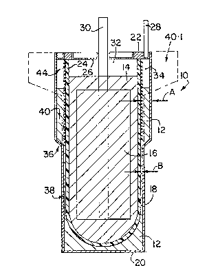
In the drawings, reference numeral 10 generally designates an
electrochemical cell in accordance with the invention. The cell 10 has
a molten sodium active anode material 12, a sodium aluminium chloride
molten salt electrolyte 14, and a cathode 16 which is immersed in the
electrolyte 14 and which in its discharged state comprises an
electrolyte-permeable porous iron matrix which is electronically
conductive and contains FeC12 in dispersed form therein as its charged
active cathode substance. Instead, the matrix could for example be of
porous nickel containing NiCl2 in dispersed form as its charged active
cathode substance. The matrix of the cathode 16 is saturated with the
electrolyte 14 and has sufficient finely divided N æ 1 dispersed therein
to ensure that, in all states of charge of the active cathode
substance, the electrolyte 14 is an equimolar mix of NaCl and AlCl3, ie
stoichiometrically exact NaAlC14.
The cell 10 has a ~ild steel outer housing or casing 18 having a base
20 for supporting it in an upright attitude, as shown. The casing 18
is sealed to an alpha-alumina insulating ring 22. An open-ended
beta"-alumina separator tube 24 is located concentrically within the
casing 18, the lower end of the tube 24 being closed and the upper or
open end of the tube 24 being glass-welded to the alpha-alumina ring 22
in sealing fashion. The open end of the tube 24 is closed by a closure
disc 26 of mild steel, sealed to the alpha-alumina ring 22. An anode
terminal post 28 is welded to the casing 18, and a cathode terminal
post 30 passes through a sealed central opening in the disc 26,
downwardly into the electrolyte 14. The lower portion of the post 30
is embedded in and in electronic contact with the matrix of the cathode
16. The matrix acts as a cathode current collector. There is an inert
gas space 32 above the electrolyte 14, and an inert gas space 34 above
the sodium 12.
1298347
The space between the casing 18 and tube 24, occupied by the sodium 12,foTms an anode compartment, and the interior of the tube 24 forms a
cathode compartment. These compartments are separated from each other
by the separator tube 24, and by the sealing of the tube 24, casing 18
and disc 26 to the alpha-alumina ring 22.
The overall charge/discharge reaction of the cell can be represen~ed bythe reaction:
discharge
2Na + FeC12 ~ 2NaCl + Fe
charge
Accordingly, sodium passes from the cathode compartment to the anode
compartment during charging, through the separator 24; and it passes
in the opposite direction during discharging. During discharging, the
volume of the Fe/FeC12 active cathode substance increases, with a rise
in the level of electrolyte 14 in the cathode compartment and a
corresponding drop in the level of molten sodium active anode substance
12 in the anode compartment; and, upon charging, there is an rise in
the level of active molten sodium anode substance 12 in the anode
compartment, with a corresponding drop in the level of molten
electrolyte 14, arising from a decrease in the volume of the Fe/FeCl2
active cathode substance.
With particular reference to Figure 1, it will be noted that the
housing 18 is necked-in at 36 so that the anode compartment defined
between the tube 24 and the casing 18 has a lower portion 38 and an
upper portion 40, the upper portion being of a greater horizontal
cross-section than that of the lower portion. In other words, the
annular space between the tube 24 and casing 18 in the upper portion 40
of Figure l, is of substantially greater width, as sho~n by A, than
that of the lower portion 38, shown by B.
Turning to Figure 2, the casing 18 has a substantially constantdiameter, but the same effect is obtained by providing an inert
cylindrical insert 42 in the lower portion-of the casing 18, in contact
with said casing 18 and spaced from the tube-24. The insert 42 may be
of solid, hollow or particulate (powder) construction. Once again, the
~298.~4~
anode compartment has an upper portion 40 and a lower portion 38, the
width A of the upper portion 40 being greater than the width B of the
lower portion, said lower portion 38 being defined between the tube 24
and the insert 42.
In Figure 1 in solid lines the upper portion 40 of the casing is shown
for a cell for use in a battery where good volumetric energy density
and efficient close packing of cells is a consideration. The upper
portion 40 thus has a relatively great depth and a relatively small
value for A. In cells for use in situations where said density and
close packing are not a consideration, the upper portion can have a
lesser depth and a great value for A, as shown in broken lines in
Figure 1 at 40.1.
In each upper portion 40, the outer surface of the tube 24 is lined by
a wick 44. This wick 44 is shown in detail in Figures 3 and 4, where
it is generally designated 44, and is shown in contact with part of the
tube 24.
The wick 44 comprises an inner layer of finely porous material 46, an
outer layer 48 of coarsely porous material, and an outermost gauze
layer 50, which holds the layers 44 alld 46 in place up against each
other and up against the tube 24.
~ !
The dimensions of the casing 18 (Figure 1) and the casing 18 together
with the insert 42 (Figure 2) are selected so that in all states of
charge of the cell the lower portion 38 of the anode compartment will
always remain filled by sodium 12, and such that, when the cell is
fully discharged, each upper portion 40 is substantially empty of
sodium 12.
During charging of the cell, sodium will enter the anode compartment,
and the level of sodium 12 therein will rise, reducing the volume of
the gas space 34, and during discharging the sodium level will drop.
It is, however, desirable that the entire outer surface of the tube 24
be wetted by sodium in all states of charge, and for this reason the
1298347
wick 44 is provided to wick molten sodi.um upwardly over the whole of
the outer surface of the tube 24.
Wicking sodium upwardly against gravily is, however, difficult, and
cannot easily be effected over substantial heights. It is for this
reason that the cells 10 are provided with their upper portions 40 and
lower portions 38, designed so that the lower portions 38 are filled
with sodium at all times. This permits wicking of sodium upwardly to
be required only in the upper portions 40, over relatively reduced
heights, less than the full height of the tube 24. In this regard it
is to be noted that the spacing B will be kept as low as possible,
being of the order of 0,1 to 0,2 mm, and the lower portion 38 extends
at least halfway up the tube 24.
With particular reference to Figures 3 and 4, it is contemplated that
the layers 46 and 48 will remain saturated with sodium at all times,
and that the gauze 50 will retain pools or droplets of sodium thereon,
as indicated at 52, when exposed to the gas space 34. In this regard
it should be noted that the materials of the wick should preferably be
easily wettable by sodium, conveniently being transition metals such as
iron, nickel, or the like. In its detailed construction, the wick 50
has a plurality of structures 54 which hold the pools or droplets 52 of
sodium in place. These structures 54 may be bucket-shaped, dispersed
in spaced relationship from one another over the outer surface of the
outer layer 48; or they may be in the form of vertically spaced
circumferentially extending gutter-like channels extending around said
layer 48. Those of Figure 3 are shown to be of part-circular
cross-section, and those of Figure 4 are shown to be of verti.cally
elongated cross-section. Naturally, if desired, a less sophisticated
gauze or mesh 50 may be used, eg of expanded metal diamond mesh
construction, provided it fulfils the function of keeping droplets 52
of sodium in contact with said outer layer 48.