Note: Descriptions are shown in the official language in which they were submitted.
~.zg~
COMPOSITE BUILDING PANEL AND METHOD
This invention relates to composite building
panels of the type formed from a synthetic layer and a
; protective cementitious layer. More particularly, this
invention relates to an improved foam panel having a
cementitious layer thereon; and method of preparation.
Composite panels for building construction
formed of a ~oam layer adhered to a protective
cementitious layer are well known. For example, one
uch panel is described in U.S~ Patent No. 3,411,~56.
Although composite panels of this type provide good
insulation, their use in exterior applications, such as
for roofs, has been hindered by a tendency of the
. 15 cementitious layer to delaminate from the foam. This
exposes the foam layer directly~to the elements~
causing deterioration of the foam and eventual leakage
of the roof. -
The delamination problem is addressed in U.S.
Patent Nos. 4,054,691 and 4,067,164 which disclose the
formation of indentations or undercut holes in the foam
surface which receive a portion of the protective,
.
35,519-F
.
~z~
--2~
cementitious coating to form a mechanical bond or grip
therebetween. Composite panels formed according to
these patents have exhibited improved resistance to
delamination, but, the problem still persists.
This is particularly true where the panels are
e~posed to frequent freeze-thaw cycles where there is
an abundance of moisture. It is. believed that moisture
tends to seep into the panel along its longitudinal
edge~ and between the foam and the protective
cementitious layer. Alternating freezing and thawing
of this moisture generates a separating action between
the layers, forcing them apart, and initiating the
ingress of even more moisture. Over a period of time,
the panel edges are exposed at their seams to the
element~ which causes leakage and loss of protection to
the underlying structure such as roofing elements.
Another difficulty with prior art composite
panels is that their edge construction provides little
re~istance to edge deformation or bending. The extreme
edges of such panels are not reinforced and are subject
to damage during shipment and from handling during
in tallatiOno
In contrast to the aforementioned prior art
this invention provides an improved composite panel
having increased resistance to delamination and
increased edge strength; and a method of preparing such
a panel.
To these ends, a presently preferred embodiment
of the invention contemplates a composite panel
containing a moisture barrier c`onstructed to prevent
delamination and having an improved mechanical grip
.
35,519-F -2-
_3_
between panel layers. The preferred embodiment,
according to the invention, provides increased edge
rigidity.
More specifically, the composite panel of this
invention includes a cementitious layer as a moisture
barrier and an underlying insulating foam layer.
Inwardly inclined, elongated grooves are formed in the
foam layer along and adjacent to at least the
longitudinal edges of the foam and preferably adjacent
both longitudinal and transverse edges for increased
delamination resistance and rigidity. These grooves
extend from one end of the foam layer to the other, and
are each inclined inwardly, toward the center of the
foam layer, from the foam surface to be adjacent the
cementitiou~ layer.
:~:
Cementitious material is then laid onto the
foam layer and at least some of the material flows into
the inclined grooves at the panel edges. Once cured,
the cementitious material filling the longitudinal
grooves forms a moisture between the layer faces. This
~` substantially eliminates edge delamination started by
the freeze-thaw cycle, and the panel remains secure
with no delamination.
' .
Several other advantages are obtained by the
composite panel of this invention. For example, the
cured cementitious material in the longitudinal and
transverse grooves forms elongated ribs or projections
which substantially improve the rigidity of the entire
panel. The grooves in the foam layer are inclined,
preferably at acute angles with respect to the plane of
the cementitious layer. Accordingly, the cementitious
35,519-F -3-
--4--
material within the longitudinal grooves forms a secure
mechanical grip, locking the two layers together.
The mechanical lock provided by the inclined
longitudinal grooves and cementitious material i9 thus
not only far greater in strength than obtained by even
the undercut multiple indentations mentioned in two of
the aforesald patents, but also.provides a moisture
barrier preventing moisture from entering the
longitudinal edges of the panel where it can initiate
the delaminating process. The invention thus
contemplates cooperating structure between two layers
of a composite panel which working together not only
produces a strong mechanical lock of one layer atop the
other, but also prevents the initial causal factor of
delamination. In addition, the moisture barrier and
meohanical lock produces a panel having a rigid edge,
less susceptible to damage from handling or shipping.
The advantages thus produced have a cumulative
beneficial effect not appreciated or suggested in the
prior art.
In still another aspect of the invention,
additional inclined grooves are formed in the foam
layer internally of the grooves located adjacent the
longitudinal and transverse edges. These internal
grooves receive the cementitious material to further
resist ingress of moisture, to enhance the mechanical
locking between layers, and to add rigidity to the
panel. Particularly, additional, spaced longitudinal
grooves are provided parallel to the longitudinal edge
grooves, and extending into the transverse grooves, for
further mechanical locking and panel rigidity.
35,519-F -4- -
.
In addition9 undercut projections as described
in the aforesaid patens can be used, or can be wholly
eliminated where suitable grooves as described herein
are used.
It should also be appr~cia.ted.that use of
inclined longitudinal grooves adjacent only the
longitudinal panel edges.will have a beneficial.effect
in substantially increasing overall panel rigidity,
resisting delamination, and in resisting ingress of
moisture along these edges.
The invention is illustrated in the drawing in
which:
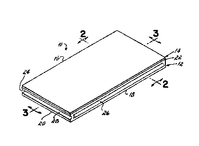
Figure 1 is an isometric view of the composite
panel of this invention;
Figure 2 is a cross-sectional view taken
generally along line 2-2 of Figure 1 showing the
long,~tudinal grooves of the panel in cross-section;
Figure 3 is a cross-sectional vlew taken
generally along line 3-3 of Figure 1 showing the
transverse grooves of the panel in cross-section; and
Figure 4 is a plan view of the foam layer of
the panel herein.
More specifically, the composite building panel
: 10 of this invention comprises a bottom foam layer 12
- having a top surface 13 and a layer 14 of cementitious
material adhered at a surface 15 therèof to surface 13.
In one present'y preferred embodiment, the composite
panel 10 is approximately two feet wide and four feet
long with the foam layer 12 about two inches thick and
the cementitious layer 14 about three-eighths inch
: 35 thick.
35,519-F -5-
.
.
--6--
The composite panel 10 includes longitudinal
edges 16, 18 and transverse edges 20, 22 having mating
tongues and grooves interconnect panel 10 with other
composite panels ~not shown). As shown in Figure 1,
the longitudinal edges 16, 18 are formed with a groove
24 and tongue 26, respectively, and the transverse - -
edges 20, 22 are Pormed with a groove 28 and tongue 30,
respectively. PrePerably, the tong~es-26, 30 and
grooves 24, 28 are formed entirely in the Poam layer
12.
PrePerably, the cementitious layer and the Poam
layer are both moisture impervious and any suitable
materials therefor, such as those disclosed in the
aforementioned patents, can be used. Such materials do
not comprise any portion oP this invention.
In the presently preferred embodiment oP this
invention, the material forming the Poam layer 12 i~
any closed-cell, generally smooth-skin Poam such as the
styrene polymer foams, styrene acrylonitrile copolymer
foams, styrene-methylmethacrylate copolymer foams,
polyvinylchloride Poams, polurethane Poams,
polyethylene foam, phenolic foams and other materials
available in cellular Poam Porm as is well known in the
art. The cementitious layer 14 is preferably of the
type disclosed in U.S. Patent No. 49067,164, although
other types oP cementitious layers may be utilized. As
descrlbed in detail in Patent No. 4,067,164, the
cementitious layer 14 is-Pormed from a hydraulic cement
; inclusive of any of the "portland cement'1 materials,
preferably modified with a prescribed styrene-
butadiene-1,3 copolymer.
.
.~
35,519-F -6-
6~
An important feature of this invention is the
formation of a good mechanical bond between the foam
and cementitious layers 12, 14, and also the formation
of a moisture barrier to prevent the ingress of
moisture from the longitudinal edges 16, 18 or
transverse edges 20, 22 into the interface formed by
the botto~ surface 15 of the cementitious layer 14 and
the -top s~rface 13 of the foam layer 12. - -
The foam layer 12 is formed with a
substantially continuous notch or channel about its
: entire perimeter. The continuous channel is preferably
in the form of inclined longitudinal grooves 32, 34
extending along the longitudinal edges 16, 18 in the
foam layer 12, connected to transverse edges 20, 22 in
the foam layer 12. As shown in Figure 2, the
longitudinal grooves 32, 34 extend downwardly from top
surface 13 of foam layer 12 immediately adjacent the
longitudinal edges 16, 18, and then inwardly at an
acute angle with respect to the plane in which the
layer of cementitious material resides, toward the
center of foam layer 12. Similarly, as shown in Figure
3, the transverse grooves 36, 38 extend from
2~ immediately adjacent transverse edges 20, 22 at the top
~urface 13 downwardly, at an acute angle, with respect
to the cementitious layer, toward the center of foam
layer~12.
The foam layer 12 is also formed with
longitudinally extending center grooves 40, 42 as shown
in Figures 2 and 4. Center groove 40 extends from the
. top surface 13 of foam layer 12 inwardly toward its
center, and the center groove 42 is inclined in the
opposite direction from the top surface 13 toward the
center of foam layer 12. Both form acute included
35,519-F -7-
6 r 3 ~L
angles with respect to the cementitious layer. As
viewed in Figure 2, the longitudinal groove 32 and
center groo~e 40 on the lefthand portion of composite
panel 10 angle inwardly to the right, and the
longitudinal groove 34 and center groove 42 on the
righthand portion of foam layer -12 angle inwardly to
the left.
The longitudinal grooves 32, 34, transverse
grooves 36, 3~, and center grooves 40, 42 are all
preferably inclined inwardly at an included angle of
about 20 to 45 relative to the top surface 13 of foam
layer 12. In additio~, such grooves are all
approximately one-fourth inch to three-eighths inch
wide and about one-half ihch deep. The grooves are
provided in the foam layer about one-quarter inch
inwardly of the respective outer edges of the foam
layer. -
In forming the composite panel 10 of this
invention, the foam layer 12 is first formed with the
grooves described above in any known manner such as
milling, slicing, cutting, routing, and the like. The
cementitious material in flowable form is then
deposited onto the top surface 13 of foam layer 12 so
that at least a portion of the cementitious material
flows into each of the grooves in the foam layer 12 as
; shown in Figures 2 and 3; and remaining integral with
-30 the cementitious layer formed on surface 13 of the foam
layer. The cemèntitious material is then allowed to
cure, forming the hardened cementitious layer 14 in
which at least some of the material has solidified
within each of the grooves in the foam layer 12.
, ' ,
~ 35,519-F -8;-
~ 2
_9_
Several advantages are obtained in the
composite panel 10 according to this invention. An
effective moisture barrier is created between the top
surface 13 of foam layer 12 and the bottom surface 15
of cementitious layer 14 to resist delamination. This
results, in part, from disposing the longitudinal
grooves 32? 34 and transverse grooves 36, 38, all of
which receive cementitious material, immediately
adjacent the longitudinal edges 16, 18 and transverse
edges 20, 22, respectively, in the foam layer 12. The
presence of cementitious material within grooves at the
very edge of the foam layer 12 helps resist the initial
entry of moisture between the facing surfaces of ~oam
layer 12 and cementitious layer 14. As further
protection against the ingress of moisture between
cementitious layer 14 from foam layer 12, the inwardly
angled longitudinal grooves 32, 34 and transverse
grooves 26, 38 define a tortuous path from the outer
edges of composite panel 10 inwardly toward the center.
If moisture does initially penetrate the edges of
composite panel 10, the tortuous path defined by the
grooves 32, 34 and 36, 38 prevents the moisture from
continuing inwardly between layers 12 and 14, thereby
resisting more severe delamination stresses in deep
internal sections of the panel caused by repeated
freeze-thaw cycles.
In addition, the angled orientation of the .
3 grooves in foam layer 12 provides a strong mechanical
interlock between the cementitious layer 14 and foam
layer 12. The cementitious panel cannot be pulled away
from the foam witho~t destruction of the ~ngled
cementitious material filling the grooves, or the foam
above the inclined grooves. This increased grip adds
., .
35,519-F -9-
--lo
to the overall rigidity of the composite panel 10 and
increases its useful life.
A further advantage of this invention is the
increase in rigidity of the longitudinal edges 16, 18
. and transver e edges 20, 22 of composite panel 10. By
placing cementitious material within grooves formed
.along the very edges in.the foam la~er 12 of the
composite panel 10, such edges are greatly strengthened
: 10 to reduce breakage during shipment and installation.
While the invention has been described with
reference to a preferred embodiment, it will be
understood by those skilled in the art that various
changes may be made and equivalents may be substituted
for elements thereof without departing from the scope
of the invention. In addition, many modifications may
be made to adapt a particular construction or material
to the teachings of the invention without departing
from the essential scope thereof. For example, both
the grooves at the panel edæe and through the panel
; interior could be made intermittent or discontinuous
for particular applications, not requiring full length
or width grooves where the full advantageous
performance of the invention is not totally necessary,
but wherein some additional strength or interlock is
helpful. Therefore, it is intended that the invention
-not be limited to the particular embodiment disclosed
as the best mode contemplated for carrying out this
invention, but that the invention will include all
embodiments falling within the scope of the appended
claims.
.
~ 35,519-F -10-