Note: Descriptions are shown in the official language in which they were submitted.
&~
RETAINING WALL CONSTRUCTION AND BLOCKS THEREFORE
This invention relates to the construction of retaining
walls and to unique blocks used in the construction of such
walls.
Retaining walls are frequently used in residential or
business landscaping to contain raised lawn or garden areas,
particularly around walkways and driveways, but also in the
creation of multi-levelled or terraced lawn or garden areas. For
most applications, the height of such retaining walls is not
great, and this invention is direction primarily to such retaining
walls having a maximum height of about 1 to 1~ meters, although
the invention may have application to retaining walls of greater
height depending upon the size and weight of blocks used in the
construction of such walls.
There are a variety of interlocking or interacting
blocks currently available for use in the construction of such
retaining walls. Such blocks are usually designed so that a
number of courses composed of similarly shaped blocks may be
arranged one atop the other in such a way that the blocks of one
course interlock or interact with blocks of the adjacent courses
to produce a retaining wall which exhibits a relatively high
degree of resistance to outward pressure exerted by the earth or
soil being retained, and which, preferably, has an external or
visible face or surface which deviates slightly from the vertical,
sloping upwardly and inwardly toward the earth or soil being
retained. Blocks used in the construction of such retaining walls
i2
are normally formed of cast concrete, and many of the blocks
currently available are suitable for their intended purpose.
However, such blocks are suitable for use in only one orientation.
In other words, when the blocks are complied to construct a
retaining wall, the currently available blocks are designed for
use only with a given face down, the opposite face up, and end
face directed outwardly to form a visible wall surface, and the
opposite end face directed inwardly toward the earth or soil being
retained. With a given block therefore, only one external surface
texture is possible. If the particular block in question has a
smooth outwardly facing end surface, such block may be used only
to produce a wall having a smooth visible face. If another
surface texture is desired, such as a texture simulating natural
cut stone, a different block, having an outwardly facing end
surface resembling natural cut stone must be employed.
Accordingly, it is an object of the present invention to
provide a construction block suitable for the production of
retaining walls or the like, which, in one orientation, may be
used to produce a retaining wall having a smooth visible
face, and, which, in another orientation, can be used to produce a
retaining wall having a visible face which resembles, in texture,
natural cut ~tone.
It is a further object of the invention that such
construction blocks be of substantially identical configuration,
and that, when arranged in either orientation, to construct a
retaining wall, the blocks will interlock or interact to resist
outward pressure exerted by the earth or soil being retained, and
lZ~8~fi2
the outer, visible surface of the retaining wall will deviate from
the vertical, sloping inwardly toward the earth or soil being
retained.
The foregoing objects are achieved in accordance with
the invention which, in a broad aspect, resides in a construction
block adapted to interact with other like blocks comprising: a
body substantially in the shape of a rectangular parallelepiped
having a first bearing face, a second bearing face opposite said
first bearing face, two side faces and two end faces; a single
transverse upstanding ridge means on said first bearing face at
one end face and having an inboard side facing toward the
remainder of said body; a single bevel means on said second
bearing face between said second bearing face and said one end
face; whereby the bevel means of said block is adapted to nest
with the inboard side of the ridge means of another like block
when a second bearing face of said like block rests upon said
first bearing face. When the blocks are assembled in courses to
produce a retaining wall, the notch in the block of one course is
adapted to nest with the inboard side of the ridge of a block in
an adjacent course whereby the blocks of one course interact with
the blocks of the adjacent course to resist pressure exerted by
the earth or soil to be retained, and the resulting retaining wall
slopes slightly from the vertical toward the earth or soil being
retained. Preferably, the ridge is of trapezoidal cross-section,
and the notch comprises a bevel of less width than the ridge.
One end face of such blocks may be provided with a
surface texture different from the opposite end face so that, when
`~A
12~
the blocks are arranged in one orientation, for example, with the
first bearing face directed down, the outer or visible surface of
the retaining wall will exhibit one texture, and, when the blocks
are arranged in the opposite orientation, for example with the
3a
~"
1~98~3%
first bearing face directed up, the outer visible surface of the
wall will exhibit a different surface texture.
Preferably, one end face of the construction block in
accordance with the invention will be smooth, whereas the opposite
end face will be rough to simulate natural cut stone to make two
sharply contrasting visible wall surfaces possible with the use of
a plurality of like blocks.
Such blocks are readily produced from a dual block which
is separable into two like construction blocks. Such dual block
will exhibit a body substantially in the shape of a rectangular
parallelapiped symmetrical about a transverse central plane and
having a first bearing face, and second bearing face opposite
thereto, two side faces and two end faces. ~pstanding transverse
ridges are disposed at each end of the first bearing face and a
transverse notch is disposed at each end of the second bearing
face. Transverse grooves are disposed in the first and second
bearing faces in the transverse central plane of the dual block
whereby the dual block may be split along the central plane into
two like individual construction blocks. Preferably, the ends of
the dual block are smooth, and, when split along the transverse
central plane, a rough end surface will be produced in the two
individual blocks so created so that two like construction blocks
will be produced, each having a smooth face at the end adjacent
the ridge and bevel, and each having a rough surface simulating
natural cut stone at the opposite end.
In drawings, which illustrate the invention,
Figure 1 is a pictorial view of a dual blocX in accordance
with the invention;
12~ 2
Figure 2 is a side view of the dual block of Figure l;
Figure 3 is a pictorial view partially in phantom and
partially broken away showing the dual block of Figure 1 separated
into two like individual blocks;
Figure 4 is a pictorial view of an alternative form of
dual block;
Figure 5 is a side view, partially in section, through a
retaining wall composed of individual blocks in one orientation to
produce a visible surface having a surface simulating a rock
face;
Figure 6 is a side view, partially in section, through a
retaining wall composed of individual blocks disposed in another
orientation to produce a visible surface having a smooth face;
Figures 7a and 7b and plan views of adjacent courses of
a rock face wall illustrating inside corner detail;
Figures 8a and 8b are plan views of adjacent courses
illustrating inside corner details of a smooth face wall;
Figures 9a and 9b are plan vie~s of adjacent courses
illuRtrating outside corner details of a rock face wall; and
Figures lOa and lOb are plan views of adjacent courses
illustrating outside corner details of a smooth face wall.
Referring now to the drawings, Figures 1 and 2 illus-
trate a dual block 10 conventionally formed of cast concrete and
having a first bearing face 11, a second bearing face 12, two side
faces 13 and two end faces 14. Disposed at each end of the first
bearing face 11 are ridges 15, and disposed at each end of the
second bearing face 12 are notches in the form of bevels 16.
~2~898~
Each ridge is trapezoidal in cross-section, and
comprises a top face 15a and sloping inner and outer side or
lateral faces 15b and 15c.
The bevel 16 forms an angle of 45 to the plane of the
second bearing face and the end face, and the sloping side or
lateral surfaces 15b and 15c of the ridge also form an angle of
45 with the plane of the first bearing face.
While the ridges and notches may be of rectangular cross
section, the tropezoidal and bevelled forms are preferred for ease
of casting and because tolerances are less demanding.
Along a central transverse plane of symmetry of the dual
block is disposed, in the first and second bearing faces, a
V-shaped splitting groove 20 and midway between the center plane
of symmetry and each end of the dual block are disposed, in the
first and second bearing faces, additional splitting grooves 21.
Figure 3 illustrates the dual block of Figure 1 which
has been split along the central transverse plane of symmetry by
conventional means, such as a hammer and splitting tool, utilizing
the splitting grooves 20 to produce two individual construction
blocks which are virtually identical, but for the rough split
surfaces 22 which resemble natural cut stone. A portion of the
individual block to the left in Figure 3 is shown in phantom, to
illustrate that the portion may be cut or split away through
grooves 21 to produce a plain filler block used in the production
of outside or inside corners of a retaining wall as will hereafter be
described. Further, the right-hand block illustrated in Figure 3
is shown with the ridge 15 partially removed at 17 by conventional
~29~3~82
means such as a hammer and chisel, to produce a block of the type
used in inside or outside corner construction of a retaining wall,
as will hereafter be described.
Figure 4 illustrates another embodiment of a construc-
tion block 30 which is essentially the same as that depicted in
Figure 1, but which is of greater length and omits the grooves 21,
but includes transverse grooves 35 of trapezoidal cross-section
similar in configuration to ridges 15, but of slightly greater
dimensions so they can readily accept ridges 15. This will ensure
that the blocks rest upon one another with their main bearing
faces in contact, and that there is sufficient tolerance to permit
the construction of retaining walls which exhibit slight concave
or convex curvature on their outer faces. In other respects, this
block is the same as that depicted in Figure 1, and like reference
numerals are utilized to designate corresponding elements. Like
the dual block 10 of Figure 1, the dual block 20 of Figure 4 may
be separated into individual blocks by splitting through the
transverse plane of symmetry utilizing splitting grooves 20.
While end faces 14 of the dual blocks of either Figure 1
or Figure 4 may exhibit any desired surface texture, normally the
end faces will be smooth to contrast with the rough texture of end
faces 22 of the individual blocks created by splitting the dual
block along the transverse central plane of symmetry.
Figures 5 and 6 illustrate the construction of a retain-
ing wall utilizing the individual blocks 10 as illustrated in
Figure 1, and individual blocks 30 illustrated in Figure 4. It
will be appreciated, that because of their greater length, and
32
therefore greater weight, the individual blocks 30 are used to
form the lower base portion of the retaining wall, whereas the
individual blocks 10 are used to form the upper courses of the
retaining wall. It will also be appreciated, that a retaining
wall could be produced entirely utilizing the individual blocks
10. However, the use of the heavier blocks 30 permits a retaining
wall of somewhat greater height to be produced than would
otherwise be possible utilizing only the smaller blocks 10. For
example, the smaller blocks alone would be useful to produce a
retaining wall of approximately 1 meter in height, unless a
retaining wall of up to about 1~ meters can readily be produced
utilizing a combination of blocks 30 to form the base of the wall
and blocks 10 to form the upper courses.
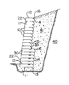
The retaining wall depicted in Figure 5 is in the nature
of a rock face wall. In other words, the rough end faces 22,
created by splitting the dual blocks 10 or 30, face outwardly, and
the first bearing face of each block faces downwardly with the
ridge of each block in the immediately adjacent upper course being
hooked behind the bevel on the second bearing face of the block
below so that the inner side face of the ridge of the upper block
nests with the bevel of the lower block and the blocks interlock
or interact to resist outer pressure from the original soil 40 or
the crushed fill 41 inserted below and behind the retaining wall
and between the retaining wall and the original soil.
It will be apparent that the shorter blocks 10 will not,
in construction of the rock face wall depicted in Figure 5, inter-
act with the foundation blocks 30, because of the difference in
length between blocks 10 and 30. Accordingly, the trapezoidal
grooves 35 are appropriately formed in the second bearing face of
blocks 30 to receive ridge 15 of blocks 10 to provide the necess-
ary interlock and interaction between the two types of block at
their interface, while retaining the near vertical slope of the
outer face of the wall. It will also be apparent that the
blocks 10 and 30 are so dimensioned that, in the rock face wall
constructions depicted in Figure 5, the nesting of the inner face
of ridge 15 with the bevel 16 of the block immediately below will
result in face 22 of the upper block being inset slightly from
face 22 of the block immediately below to result in an outer wall
surface deviating slightly from the vertical, and sloping slightly
inwardly toward the soil be retained.
Figure 6 illustrates the construction of the retaining
wall, utiliæing blocks identical to those utilized in Figure 5,
but having the smooth end faces 14 directed outwardly to form the
visible retaining wall surface, which will here be described as a
smooth face wall, with the rough surfaces 22 resembling natural
cut stone, formed from splitting of the dual block, directed
inwardly toward the soil being retained.
In the smooth face wall constructing depicted in Figure
6, it will be seen that the orientation of the blocks 10 and 30
are reversed in that the first bearing face 11 is now directed
upwardly, the second bearing face 12 is directed downwardly, the
smooth end 14 is directed outwardly to form the visible retaining
wall surface, and the rough surfaced end 22 is directed inwardly
toward the soil being retained. The blocks still interlock to
_ 9 _
~S~a~2
resist the outward pressure of the soil 40 being retained, as the
inner face of each ridge 15 nests with bevel 16 of the block
immediately above, including the interface between blocks 10 and
30. Again, the blocks are so dimensioned that, when arranged as
depicted in Figure 6, the outer surface of the wall deviates
slightly from the vertical, sloping slightly inwardly toward the
soil being retained.
To construct a retaining wall as depicted in either 5 or
6 one should excavate for footing to a minimum depth of 250 milli-
meters below finished grade at the front of the wall, or untilfirm original soil is reached. The excavation should allow for
the thickness of the wall plus a minimum depth of 250 millimeters
to allow for compacted crushed granular back fill behind the wall.
Crushed granular material should then be placed within the footing
excavation and compacted in maximum 150 millimeter layers to
provide a firm wall base. The first course of blocks should then
be placed and levelled so that the top of the course is flush with
the desired finished grade in front of the wall. Of course the
dual blocks must be split with hammer and chisel, or similar
splitting tool, along the transverse central plane of symmetry.
Either end face can be exposed simply by reversing the block as
depicted in either Figures 5 or 6. Slight spaces may be left
between certain of the blocks near the base of 'he wall for
drainage and of course the blocks should be displaced a distance
of about one half the width of each block from course to course in
the conventional manner of laying conventional bricks or retaining
wall blocks. As the height of the wall increases with the
-- 10 --
125~ 2
addition of each course of blocks, the space behind the retaining
wall and between the back of the retaining and t'ne original soil
40 should be back filled with suitable granular fill 41 ensuring
that the material used for the backfill is adequately compacted as
the work proceeds. When the wall is complete, the backfill
material may be covered with topsoil and landscaped to promote
surface water runoff over the top of the wall.
Figures 7, 8, 9 and 10 each illustrate adjacent courses
of blocks 10 arranged to form an inside corner of a rock face
wall, an inside corner of a smooth face wall, an outside corner of
a rock face wall, and an outside corner of a smooth face wall
respectively. It will be seen that half blocks 40, as depicted in
Figure 3, are utilized to fill in corner areas where spaces have
been left as a result of the staggered half block arrangement of
blocks 10 from course to course. Further, it will be noted that
sections of the ridges 15 have been removed as shown in Figure 3
to avoid interference, particularly with the filler blocks 40, in
the corner areas.
While the blocks may be made in any suitable size, a
typical individual block 10 for ordinary usage will have a length
from end 14 to end 22 of 300 millimeters, a width between sides 13
of 300 millimeters, and a thickness from the first bearing face 11
to the second bearing face 12 of 100 millimeters. Of course in
the dual block unit depicted in Figures 1 and 2, the total length
of the unit from one end face 14 to the other end face 14 will be
600 millimeters (double the length of an individual block) and the
grooves 20 will be disposed in the central transverse plane at a
distance of 300 millimeters from either end, with the grooves 21
being disposed midway the grooves 20 and each end face 14, at a
distance of 150 millimeters from each end face. The ridges have a
width at the base (at the first bearing surface 11) of 44
millimeters and a height of 16 millimeters. Th~ bevels 16 have a
depth of 37 millimeters, i.e., the distance from the imaginary
corner of the block formed by the plane containing end face 14 and
the plane containing the second bearing face 12 to the respective
bevel edge is 37 millimeters.
The larger blocks 30, used for base construction have a
total length of 900 millimeters and a half length, when split
along grove 20, of 450 millimeters. The grooves 35 have a depth
of 18 millimeters and a width, at face 12, of 75 millimeters.
The foregoing dimensions provide sufficient tolerance,
as between grooves 35 and ridges 15 to permit the construction of
retaining walls with a degree of curvature, either convex or
concave. Further, these dimensions result in a 7 millimeter
setback or inset as between the outer face of a block 10 in one
course and the outer face of a block 10 in the course immediately
above.
While obviously the foregoing dimensions may be varied
depending upon the size and weight of blocks desirable for any
particular purpose, the relationship between the bevel 16 and
ridges 15 should be such that, when the bevel 16 nests with the
inboard lateral surface 15b of ridge 15, the outer face of the
wall so formed will have an appropriate deviation from the verti-
cal, with a slight incline toward the soil being retained.
~2~ 2
As will be apparent from the foregoing, the novel
construction block in accordance with the invention permits, with
the utilization of a single block form, retaining walls to be
produced which at the option of the builder, exhibit a visible
wall surface having a smooth texture, or a rough texture resem-
bling that of natural cut stone. This is accomplished simply by
reversing the orientation of the individual blocks when construct-
ing the different wall forms, and, regardless of the orientation
selected and the wall form desired, the blocks of adjacent courses
will interlock or interact to resist the outward pressure exerted
by the soil and aggregate material being retained. By appropriate
dimensioning of the blocks, and particularly the ridges and
bevels, the completed wall may have any predetermined slope
depending upon what may be considered optimum for the particular
purpose for which the blocks are designed.
While different types of blocks have been illustrated,
one being somewhat larger and heavier for use in forming the lower
portion of a retaining wall, and the other being smaller, and
hence lighter, for use in forming the upper courses of a retaining
wall, it will be appreciated that, for many applications, only the
smaller blocks will be required, and that retaining walls may be
composed completely of the smaller blocks. The larger blocks are
used primarily only when there is a re~uirement for a wall having
somewhat greater height than should be constructed with only the
smaller blocks. However, it will be appreciated, that, as the
size and weight of the blocks may be varied, without varying their
fundamental shape, walls of greater heights may be constructed
- 13 -
~ ~ ~
with the use of blocks comparable to the smaller blocks, but
having larger dimensions in width, length, thickness, or all
three.
While the preferred embodiments of this invention have
been described and illustrated, it will be appreciated that varia-
tions and departures therefrom may be obvious to those persons
skilled in the particular field to which this invention relates
without departing from the spirit or scope of the invention as
defined in the accompanying claims.
- 14 -