Language selection

Search

Patent 1299046 Summary

Third-party information liability

Some of the information on this Web page has been provided by external sources. The Government of Canada is not responsible for the accuracy, reliability or currency of the information supplied by external sources. Users wishing to rely upon this information should consult directly with the source of the information. Content provided by external sources is not subject to official languages, privacy and accessibility requirements.

Claims and Abstract availability

Any discrepancies in the text and image of the Claims and Abstract are due to differing posting times. Text of the Claims and Abstract are posted:

  • At the time the application is open to public inspection;
  • At the time of issue of the patent (grant).
(12) Patent: (11) CA 1299046
(21) Application Number: 1299046
(54) English Title: COMBINE HARVESTER
(54) French Title: MOISSONNEUSE-BATTEUSE
Status: Expired and beyond the Period of Reversal
Bibliographic Data
(51) International Patent Classification (IPC):
  • A01D 41/12 (2006.01)
  • A01F 12/18 (2006.01)
  • A01F 12/30 (2006.01)
(72) Inventors :
  • HEMKER, HEINRICH (Germany)
  • HEIDJANN, FRANZ (Germany)
(73) Owners :
  • CLASS OHG
(71) Applicants :
  • CLASS OHG (Germany)
(74) Agent: SMART & BIGGAR LP
(74) Associate agent:
(45) Issued: 1992-04-21
(22) Filed Date: 1988-10-21
Availability of licence: N/A
Dedicated to the Public: N/A
(25) Language of filing: English

Patent Cooperation Treaty (PCT): No

(30) Application Priority Data:
Application No. Country/Territory Date
P 37 35 669.0 (Germany) 1987-10-22

Abstracts

English Abstract


COMBINE HARVESTER
ABSTRACT
The invention relates to a combine harvester having a
threshing mechanism which operates in the tangential flow mode and
consists of a threshing drum and threshing concave, together with straw
walkers, a return floor and sieve means. In order to permit an increase in
the speed of forward travel and machine capacity in a harvesting
operation without an increase in the grain losses, it is proposed that
arranged downstream of the straw walkers is a per se known separating
apparatus which operates in the axial flow mode and which comprises a
rotor and a separator housing.


Claims

Note: Claims are shown in the official language in which they were submitted.

THE EMBODIMENTS OF THE INVENTION IN WHICH AN EXCLUSIVE
PROPERTY OR PRIVILEGE IS CLAIMED ARE DEFINED AS FOLLOWS:
1. A combine harvester comprising a chassis, a housing, a
threshing apparatus which operates in a tangential flow mode and
which comprises a threshing drum and a concave, straw walkers to
which threshed crop material is fed, a return floor arranged below
the straw walkers, a sieve means, and a separating apparatus
arranged downstream of the straw walkers in the direction of straw
flow, and mounted at least partially in the combine harvester
housing, said separating apparatus operating in an axial flow mode
and comprising a rotor and a housing.
2. A combine harvester according to claim 1 wherein the
separating apparatus can be selectively brought into operation.
3. A combine harvester according to claim 2, wherein the
housing of the separating apparatus includes at least one
pivotable segment which, in conjunction with a displaceable crop
material guide flap, is operable selectively to bring the
separating apparatus into operation.
4. A combine harvester according to any one of claims 1 to
3 wherein the separating apparatus extends beyond the width of the
combine harvester housing and operates in a double-flow mode with
a central crop material intake opening and two lateral crop
material discharge openings.

5. A combine harvester according to any one of claims 1 to
3 wherein the separating apparatus is above the rearward end of
the return floor.
6. A combine harvester according to any one of claims 1 to
3 wherein grain collecting troughs and conveyor augers are
provided below and separating apparatus in the region of the
lateral ends of the separating apparatus and project beyond the
width of the combine harvester housing, said grain collecting
troughs and conveyor augers being operable laterally to feed the
grain which passes through openings in the housing of the
separating apparatus to the return floor.
7. A combine harvester according to any one of claims 1 to
3 wherein a feeder drum having entrainment members is arranged
above the ends of the straw walkers in the region in front of the
crop material intake opening of the separating apparatus.
8. A combine harvester according to claim 7, wherein said
feeder drum operates in the undershoot mode.
9. A combine harvester according to any one of claims 1 to
3 or 8 which includes two crop material discharge openings and
wherein the housing of the separating apparatus is provided on its
inside with guide bars for leading the crop material to said two
crop material discharge openings.
10. A combine harvester according to any one of claims 1 to

6
3 or 8 which includes a plurality of lateral discharge openings
for discharging crop material from said separator, wherein guide
means is associated with said discharge openings for centrally
bringing together the crop material discharged therefrom.
11. A combine harvester according to claim 10, wherein said
guide means comprises guide plate means.
12. A combine harvester according to any one of claims 1 to
3, 8 or 11 including two lateral openings for discharging crop
material from said separator, wherein a straw chopper unit is
associated with each of said lateral openings.
13. A combine harvester comprising a threshing drum and
concave which operate in a tangential flow mode, straw walkers
downstream thereof, and a transverse separating apparatus which is
arranged to receive straw discharged by the straw walkers, which
operates in an axial flow mode and which comprises a rotor and a
separator housing therearound.

Description

Note: Descriptions are shown in the official language in which they were submitted.


~29~
COMEIINE HARVESTER
.
The invention relates to combine harvesters.
The speed of -forward travel of many combine harvesters in a
harvesting operation is limited by the fact that with hiyh throughputs the
straw wall<ers are no longer capable of separatillg oFf residual graill to a
satisfactory extent so that excessive amounts of grain are discharged with
the straw and lost.
According to one aspect, the invention provides a combine
harvester comprising a threshing drum and concave which operate in a
tangential flow mode, straw wall<ers downstream thereo-f, and a
transverse separating apparatus which is arranged to receive straw
discharged by the straw walkers, which operates in an axial -flow mode and
which comprises a rotor and a separator housing therearound.
According to another aspect, the invention provides a combine
harvester comprising a chassis, a housing, a threshing apparatus which
operates in a tangential flow mode and which comprises a threshing drum
and a concave, straw walkers to which threshed crop material is fed, a
return floor arranged below the straw wall<ers, a sieve means, and a
separating apparatus arranged downstream of the straw walkers in the
direction of straw flow, and mounted at least partially in the combine
harvester housing, which operates in an axial flow mode and which
comprises a rotor and a housiilg.
Russian Patent No. 220662 discloses a form of separator which
operatPs in the axial flow mode and which may be modified for use in
embodiments of the inventior7.
The invention will now be described by way of example with
reference to the drawings in which:
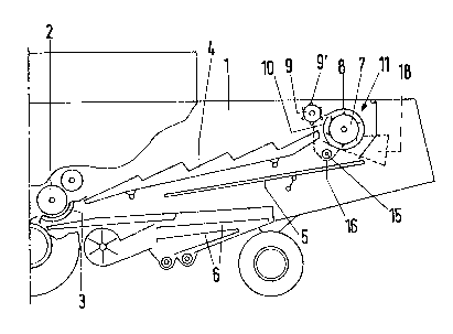
Figure 1 is a diagrammatic side view nf part of a combine
harvester designed in accordance with the invention,
Figure 2 is a diagrammatic plan view of part of the structure
shown in Figure 1,
Figure 3 is a perspective view of the rearward part of the
combine harvester with the housing broken away,
Figure 4 is a diagrammatic side view of the axial separating
.

~go~
unit shown in Figure 3 in the operatiYe position, and
Figure 5 is the view shown in Figure 4 but with the axial
separating unit in the inoperative position.
Reference numeral 1 denotes the housing of a comhine
harvester which is rnounted on a chassis (not shown) and which
accornmodates a threshing apparatus which operates in a tangential flow
mode and which is -formed from a threshing drum 2 and a threshing
concave 3, adjoining straw shakers (straw walkers) 4, a reciprocating
return floor 5 and a conventional grain winnowing and cleaning unit
comprising a fan, grain and returns augers and a reciprocating screen-
carrying shaker shoe or sieve means 6, grain and chaff being fed to the
front of the winnowing and cleaning unit by three routes, i.e. through the
concave, via the straw walkers ~ and via the return f loor 5. Disposed
downstream of the straw walkers 4 is an a~ial Flow separating unit ll
comprising a rotor 7 with beater bars and a housing 8. A feeder drum 9
having entrainrnent projections 9' is disposed above the ends of the straw
walkers 4 in front of the full-width crop material intake opening 10 of the
axial -flow separating unit 11 for ensuring trans-fer into the unit ll of the
crop material which comes from the straw walkers 4 and which includes
residual grain. The straw wail<ers 4 may be of the conventional box beam
type with openings in the upper sur-face through which grain and chaff
may drop into their interior, the slope of the lower walls of the beams
ensuring that the grain and chaff is returned to the front oF the winnowing
and cleaning unit. Grain and~chaff also drops down between the beams
onto the floor 5.
The unit 11 is ~basically of known construction but is modified
as described below.
As shown in Figures 4 and 5 of the drawing, the unit 11 rnay be
brought into th~ operating position only as required. For that purpose, a
segment 8' of the housing 8 can be pivoted away by way of a hydraulic or
pneumatic jack 12 and a linkage 13, 13' formed by the rnain Flap portion
13 and a pair of levers 13' (only one of which is shown). The arrangement
also includes a pivotable guide flap ~14 which can he actuated in a manner
::

~9~
not shown in the drawings and which screens off the return flour 5 when
the straw coming from the straw ~alkers 4 is to flow out of the harvester
housing without being subjected to additional processing by the unit 11.
Tile grain which is separated out in the axial separating unit
11 passes through openings 8" in the rotor housing ~ onto the return Floor
5, more specificalLy either directly or by way of conveyor augers 15 and
associated collecting troughs 16 which are arranged below the lateral ends
of the unit 11, these ends projecting beyond the width of the harvester
housing 1. The drawings clearly show that the unit 11 is mounted above
the return floor 5. For that purpose, the return floor 5 possibly has to be
increased in length, in comparison with l<nown constructions. The crop
material coming from tl-e straw wall<ers ~ is fed to the axial separating
unit 11 centrally by way of the intake opening lû; from there it is moved
under the effect of helical guide bars 17 on the housing 8 and beater
members on the rotor 7 towards the right and the left and it then leaves
the unit 11 in the Form of threshed-out straw, by way of lateral discharge
openings 18 at each end. During passage of the crop material axially
along tlle unit 11, grain is separated out by dropping through openings 8"
onto return floor 5 or, at the ends of the unit 11, into the troughs 16.
The discharge openings 18 may be provided with conventional
straw chopper units (not shown) or the straw discharged therefrom may be
combined into a single central swath on the ground by~ guide plates or tlle
Iike (not shown).
'
.

Representative Drawing
A single figure which represents the drawing illustrating the invention.
Administrative Status

2024-08-01:As part of the Next Generation Patents (NGP) transition, the Canadian Patents Database (CPD) now contains a more detailed Event History, which replicates the Event Log of our new back-office solution.

Please note that "Inactive:" events refers to events no longer in use in our new back-office solution.

For a clearer understanding of the status of the application/patent presented on this page, the site Disclaimer , as well as the definitions for Patent , Event History , Maintenance Fee  and Payment History  should be consulted.

Event History

Description Date
Inactive: IPC from MCD 2006-03-11
Inactive: Adhoc Request Documented 1996-04-21
Time Limit for Reversal Expired 1995-10-22
Letter Sent 1995-04-21
Grant by Issuance 1992-04-21

Abandonment History

There is no abandonment history.

Owners on Record

Note: Records showing the ownership history in alphabetical order.

Current Owners on Record
CLASS OHG
Past Owners on Record
FRANZ HEIDJANN
HEINRICH HEMKER
Past Owners that do not appear in the "Owners on Record" listing will appear in other documentation within the application.
Documents

To view selected files, please enter reCAPTCHA code :


To view images, click a link in the Document Description column. To download the documents, select one or more checkboxes in the first column and then click the "Download Selected in PDF format (Zip Archive)" or the "Download Selected as Single PDF" button.

List of published and non-published patent-specific documents on the CPD .

If you have any difficulty accessing content, you can call the Client Service Centre at 1-866-997-1936 or send them an e-mail at CIPO Client Service Centre.


Document
Description 
Date
(yyyy-mm-dd) 
Number of pages   Size of Image (KB) 
Cover Page 1993-10-28 1 14
Abstract 1993-10-28 1 17
Claims 1993-10-28 3 91
Drawings 1993-10-28 3 89
Representative Drawing 2003-03-19 1 13
Descriptions 1993-10-28 3 116
Fees 1994-03-11 1 26