Note: Descriptions are shown in the official language in which they were submitted.
9321~
Title: ~ppara~u~ ror manuracturing a plastic nallow body
wi~h a blcw-molded body part.
The invention relates to an apparatus for manufacturing
a hollow body rrom thermoplastic plastic material, said
hollow body comprised of an injection-molded head piece, a
body part formed by blowing, e.~., blow molding~ a preform
segment which segment is integral with the head piece, and
possibly a bottom member rormed by press-rorming the
preform segment, wherewith the said apparatus comprises a
ring-shaped nozzle wherein a ring-shaped nozzle opening is
derined between a nozzle cone piece (hereinafter "cone
piece") and a nozzle openin~ piece (hereinarter "nozzle
piece"), said apparatus rurther comprises a withdrat~a!
device operative with respect to the ring-shaped nozzle,
which withdrawal device is a~ially reciprocally movable and
has a recess, and said apparatus comprises a blow mold with
a plurality or Diow moid parts which are la~erally
reciprocally movable.
In a known apparatus or the type described
(Ger. Pat. 2,~28,029), the prerorm segment is press-rormed
only to form the bottom pieces of the blow-~olded parts, and
is then blown, wherewith the ring-shaped nozzle opening is
closed by means of the outer edge of the opening of the
aforesaid recess~ which recess opening faces the ring-shaped
nozzle, and its said outer edge is also the outer edge of the
head-piece space in the said recess~ and wherewith, before
~Z~3~6
~ach Dlowin3, rhe ring-shaped noz~le opening is a direct
continuation of the prefo~m tube secment. There are numerous
?ossible for~s of body parts or hollow bodies which cannot be
fabricated wi~h this apparatus.
Accordinglv, it is an object of the invention to devise
an apparatus oE the type described initiallv supra, which
enables body parts o~ hollow bodies to be manufactured which
have different and/or novel forms. This object is achieved
according to the invention in that an additional mold device
is provided for an additional forming o~eration? in addition
to blowing and possible bottom pressing) operative on the
preform segment adjoining the head piece and involving the
walls or the body part or the hollow bodv ~ wherer~ith said
additional mold device provides difrerent di~ensions ~nich
are orfset with respect to the r~ng-shaped nozzle opening.
Before the blowing, an additional molding of the
prerorm segment is carried out, whereby a correspondingly
shaped hollow body is produced from the .hus ~olded prerorm
segment; whereas previously according to the state OL- the
art the preform segment was merelv e~truded from the
noz71e openln.g and m~olded bv ~lowi.ng into the blow mold.
Because or the deviation between the transverse radial
dimensions of the nozzle opening and the o~her parts of the
device, r.~hich deviation is absent with known apparatuses ,
special configurations of the preform segment can be produced
prior to the blowing operation.
A second object of the invention is to devise an
apparatus of the type described initially supra whereby a
...- ,:
9326
noliosl bodJ ~a~J be ;nanuractured the body par~ of which is
flush with the outer edge o the head piece but wherewith
said body part undergoes, i.e., has undergone blowing,
e.g , blow molding . This object is achieved according to
the invention in that:
-- The ring-shaped nozzle opening is displaced radially
inward with respect to the outer edge of the opening of the
recess in the withdrawal device ! ~hich latter opening is
directed toward the ring-shaped nozzle, and
-- The closed blow-mold parts leave free the region of the
said recess opening which radially outwardly e~tends beyond
the nozzle opening.
. ~n injection-molded head piece is produced. Its
diameter on its part directed toward the ring-shaped nozzle
is greater than the diameter of the pressed, i.e., e~.truded
tubular prerorm segment . The pretorm segment is blown,
as is custQmary, to provide a thin t~all and to save plastic.
For given desired diameters of the head ?iece and the
hollow body, the inventive difference in ,-ansverse or ~adial
dimensions enables a more substantial widening of the body
part ~o be achieved in the blowing operation. The blo-wn
region of the prerorm segment adjoins the injection-molded
head piece and is fused to it. The e~terior of the blow
region of the preform segment is hot enough, without
additional measures being employed that it will solidly fuse
with the injection-molded head piece; the pressure developed
by the blowing of the preform segment i5 sufficient to
effect this fusing together .
~i'`.,
. , . . .... , , .. , .. , .. -.. ~ . ., .~
~Z~3~
L~ is ?ar-icularlv advantageo-ls ir .;~e inner wall
surrace or ~he closed blow-mold parts adjoins the outer edge
or the recess opening or the recess ~hich opening is
directed toward the ring-shaped nozzle. In some hollow
bodies e.g. weapons cartridges, the outer diameter of the
body part is equal to the outer diameter or the injection-
molded head piece. The blowing is then car~ied out with the
result of reduction of the wall thickness of the tubular
region or the preform segment .
It is rurther particularly advantageous~ in a
different e~bodiment, i; the the inner wall of the closed
blow-mold oarts is at a distance from the outer edge of the
ring-shaped nozzle opening. .~ bottomless hollow-body body
part is ror~ed wherein the tubular re~ion o- the prerorm
segment 3 disjoint rrom the nozzle
openin~ àue to the fact that the plastic is severed and
blown. The outer diameter or the body ?art between the
.~ithdrawal device and the r1ng-shaped nozzl- can be lar,er
than the diameter or the nozzle opening.
It is also particularly advanta~eous ir when tne
withdrawal device rests on the ring-shaped nozzle a ring-
like e~tension of the ring-shaped nozzle extends into the
recess o~ the withdrawal device , and ir a narrow extension~
e.g. a blow nozzle, on the withdrawal device extends into
the said ring-like extension of the ring-shaped nozzle .
The use or this ring-like extension on the ring-shaped
nozzle and this narrow extension on the withdrawal device
enables recesses and the like to be produced in the head
~L29~3~
piece, .~hereb~i ma~erial is saved. Because the distance~ [in
the radial sense between the laterallv outer part of the
e~tension~ on the ring-shaped nozzlel and the inner edge or
the nozzle opening is very small, when the tubular preEorm
is being e~truded the said e~tension, on the ring-shaped
nozzle is retracted; in this way, the pre~orm cannot adhere
to the said e~tension. ~ ring-shaped wall of the head piece
is produced between the narrow e~tension~ on the withdrawal
device and the ring-like e~tension (on the ring-shaped
nozzle,
It is particularly advantageous also if, during
e~trusion, the rinC width of the ring-snaped nozzle opening
is at most e~ual to the transverse distance between the
outer edge OL the nozzle opening and the outer edge of the
opening in the recess on the withdraw&l device , which
latter opening races the ring-shaped nozzle. ~his
dimensionin~ gives satisractory savings or ?lastic while
producing a rirm fusion where the head ?i~ce and bodv piece
~oln
~ third object or the invention is to devise an
apparatus or .he t-vpe described initially supra, r;7herein the
outer diameter or the body part is unusually large relative
to the outer diameter of the head piece. This object is
achieved according to the invention in that there is a radial
distance between ~he ring-shaped nozzle opening and the outer
edge of the head piece cavityt i.e.,the part of the
recess in the withdrawal device wherein the head piece is
molded , with the outer edge of the head piece cavity being
;~:9~32~
radially outward or the ring-shaped nozzle opening, wherewi~h
the side or the recess facing the ring-shaped nozzle 'nas a
disc-s~aped space r.~hich radially e~tends beyond the head
piece cavity, and when the withdrawal device rests on the
rin~-shaped nozzle the edge regions of said disc-shaped space
e~tend over~ but not necessarily beyond, the ring-shaped
nozzle opening.
The outer diameter of the tubular segment of the blown
blow-molded prerorm is greater than the outer diameter or
the head piece because the injection molded disc forms a
shoulder and cover or the head piece. Because the disc
contributes to the diameter or the hollow body, in the
blowing operation one achieves a ho!low body diameter which
is ~uch greater than that which can be acnieved t~ith a
preform ~hich has the same wall thickness as the pretor~
according ta the invention and which otherwise corresponds
to) i.e. has the same radial dimensions as the head piece.
For a preform with a given wall thic~ness, there is a limit
to the e~tent to which it can be radially blown. The
diameter ot the e~truded tubular part is increased.
It iâ pâr~Lcularly ad~antageous if a reciprocally
movable plunger is provided in the nozzle cone piece,
wherewith the end face or the plunger bounds the disc space
in the recess of the withdrawal device . This plunger can
be used to reduce the thickness of the injection-molded disc,
to a degree not achievable with injection molding alone .
It is further particularly advantageous if a blow
nozzle extending into the recess of the withdrawal device
~,,
~z~
also e:c~ellds into a bore o~ the ring-sha?ed nozzle when the
withdrawal de~ic2 rests on the ring-shaped no~zle. Although
the ring-shaped nozzle does not have an extension from it
which extends into the said recess, and the blow nozzle on
the withdrawal device does not end in the material of the
head piece, it is possible to carry out blowing wnich
originates from the withdrawal device.
It is also particularly advantageous ir the diameter or
the disc space is at least twice that of the head piece
cavity at the transition to the disc space. This widening is
achievable in any case, and even greater widening may be
achievable ; it provides a substantial increase in the
diameter or the hollow body.
A ~ourth object of the invention is to devise an
apparatus of the ~ype described initially supra wherein the
outer diameter or the body part or the manufactured hollow
body is in certain regions smaller than the diameter of the
extruded un-blo~tn tubular segment. This object is achieved
according to the invention in that a molding extension is
provided on a reciprocally movable mandrel, wnich molding
extensiorl extends between radially inwardl-v projecting
regions of the closed blow-~old parts, sucn that said
inwardly projecting regions or the blow-mold pa~ts press
the corresponding parts of the preform segment against said
molding extension, wherewith the ring-shaped nozzle opening
is radially outwardly configured with respect to the outer
contour of the molding extension.
After the extrusion, the ~olding extension is advanced
~ ~"
, .. . . , . .. .. .. ., ~ .. ~ ,.. .
.... . .. ~ . . . .... .. . . .. .
~993~6
~ -o~nr~ard . and serves 2S a tool ~or .o!ming the interior
conriguration or the corresponding body part region, which
configuration is or reduced diameter; and said molding
e~tension also serves as a support member for the radial
compression of a region of the tubular preform by the blow-
mold parts. When the blow-mold parts are moved together,
their radially inwardly projecting regions press the
prerorm radially inwardly against the molding e.~tension.
As a resuit, the outer diameter is reduced, and the preform
segment in this region is not blown outward .
The molding extension can be inserted rrom the
withdrawal device or from the rino-shaped noz~le. It
determines the wall thickness and the bottom thickness.
It is particularly advantageous ir the reciprocally
movable mandrel comprises the blowing device with blow
openings. The mandrel serves to move and position the
molding extension, and is also integrated into tne olowing
means.
It is further particularly advantageous ir the molding
e~tension is installed opposite~ i.e., to runction oppositely
to, a reciprocally movable plunger~ wherewith a region of the
preform can be presse.d between the free ends of the molding
extension and plunger , respectively . The extruded preform
may also undergo press forming in the d~rection.
It is also particularly advantageous if the molding
extension is provided on the withdrawal device and the
plunger is provided on the ring-shaped nozzle. In this way a
, .. -- ~
~ '?`",
~g3~6
hollow bod-~ can be ?roduced ~vhich is closed on the bottom and
open on the top~ to allow penetration or the molding
e~tension .
It is particularly advantageous also if the molding
e~tension projects a~ially even when the withdrawal device
rests on the ring-shaped nozzle, wherewith the molding
e~tension e~tends into one or said devices. Thus, ir the
molding e~te~sion is mounted on the withdrawal device, it
e~tends into the ring-shaped nozzle; and ir mounted on the
ring-shaped nozzle, it e~tends into the withdrawal device.
f~ccordingly, it not necessarv to provide drive means to
retract the m~lding e~tension into the device on ~thich it is
mounted.
Prererred embodiments of the invention are illustrated
in the dra~tings.
Fig. I is a schematic vertical cross section o an
apparatus for producing a plastic hollow bodv having a
bLow-molded body part;
Fig. 2 is a vertical cross sectional view of essential
parts of a second apparatus for producing a plastic hollow
bodv having a blow-molded body part. in a first operating
position;
Fig. 3 shows the apparatus of Fig. 2 in a second
operating position;
Fig. 4 shows the apparatus of Fig. 2 in a third
operating position;
Fig;. 5 is a vertical cross sectional view of essential
parts or a third apparatus for producing a plastic
.. . . --- ` ,, . - . -- - :
~L~9~32~
noliow bod~ having a blow-moLded bocly part, in a rirst
.
operatlng posltlon;
Fig. 6 shows the apparatus of Fig. 5 in a second
operating position;
Fig. 7 shows the apparatus of Fig. 5 in a third
.
operatlng posltlon;
Fig. & is a vertical cross sectional view of essential
parts or a rourth apparatus for prod~ucing a plastic hollow
body having a blow-molded body part, in 2 first operating
posltlon;
Fig. 9 shows the apparatus or Fig. 8 in a second
operating position; and
Fig. i.O shows the apparatus of Fig. 8 in a third
operating position.
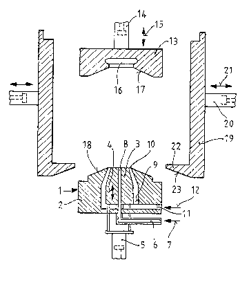
The apparatus according to Fig. 1. has a rin~-shaped
nozzle 1., comprised or a fixed nozzle piece 2 wherein a cone
piece 3 is reciprocally movable (arrows 4) by a piston and
cylinder device 5. Compressed air is supplied to the cone
piece 3 from below, via a tube 6 (arrow 7). This air exits
the cone piece at the top via a centrally
disposed blow opening 8. The cone piece 3 and nozzle piece 2
together define a ring-shaped channel 9 which upwardly merges
into the ring-shaped nozzle opening 1Ø Thermoplas~ic
plastic is fed to channel 9 from t'ne bottom via a tube 1.1
(arrow 1.2). Toward the nozzle opening lO, the cone angle of
the cone piece 3 is smaller than the cone angle of the
inner surface of the nozzle piece 2 J SO that ~he nozzle
opening 10 is closed when the cone piece 3 is advanced
~,,:j~
... . . . ......... ,., .......... . . ..... ..... ~ . .
:~99;~
upwa rd .
~ withdrawal device 1.3 is prov~ded above the ri.ng-
shaped nozzle 1, which de~ice ]3 is reciprocally movable
(arrows L5) by a piston and cylinder device 1.4. Device i.3 is
provided on its lower side with a recess i.6 having an
undercut or other form-interlocking configuration (not
illustrated) whereby the withdrawal device may be separated
into a plurality of pieces and reassembled. A support
surface 1.7 on the withdrawal device 1.3 is radially obliquely
inclined, and viewed axially has the shape of a circular
ring. .~n end surface 18 of ~he nozzle piece 2 matches
support surrace 1.7.
On bot~. lateral sides or the ring-shaped nozzle 1 and
withdrawal device 13 a ~low-mold piece (]9, 1.9) or a two-
piece blow ~old is pro-vided. The pieces L9 are each
reciprocally movable (arrows 21) by a respective piston and
cylinder device 20. Each blow-mold piece i.9 has a bottom
member 2 having an inclined support sur~ace 23 which can
rest on the seat surface 1.8 of the nozzle ?iece 2.
The appara~us of Figs. 2-4 has a largely similar
structure to that of Fig. I; accordingly the same reference
numerals and description apply , mutatis mutandis . The
differences will be described. These inciude a blow nozzle
24 on the withdrawal device 13, which nozzle ~4 extends into
the middle of the recess L~ and further toward the ring-
shaped nozzle 1. The blow nozzle 24 has a staged offset
configuration in the recess 1.6, and is disposed on a tube 25
which is reciprocally movable (arrows 27) by a piston and
.
i~9~3Z6
cvlinder de~ice 26. Compressecl air is passed via a bore `~
into the tube 25 and blow nozzle 24. Thus in this embodiment
the blo~ing air is fed both from the withdrawal device 13 and
from the rin~-shaped nozzle 1. When the withdrawal device 13
rests on the ring-shaped nozzle 1. (Fig. 2), the blow nozzle
24 e~tends into a bore 29 in the ring-shaped nozzle L ,
without entirely occupying said bore 29 in its a~ial extent.
The blow nozzle 24 inserted in the bore 29 serves to block
blow opening & during injection, i.e., injection-molding .
In the apparatus according to Figs. 2-4, the cone piece
3 accommodates a mandrel 30 which is reciprocally movable
(arrows 32) by a piston and cylinder device 31, and has tube
6 disposed in it which runs to the blow opening 8. The upper
part o~ ~andrel 3~ bears a ring-shaped projection 33 which
extends into recess 1.6 and accommodates 310w nozzle 24.
.~ccording to Fig. 2, thermoplastic plastic 34 is injected
through nozzle opening 1.0 into recess 16 to form a head piece
35. Then, according to Fig. 3, a tubular preform segmen~ 36
is withdrawn, i.e., e~truded , with the nozzle opening ]0
being partly closed by upwardly advancing the cone piece
3. According to Fig. 4 the plastic in the nozzle opening 10
is severed, ~y fully upwardly advancing the cone piece 3
which has a conical surface having a smaller cone angle
than the cone angle of the inner surface of the nozzle piece
2. The blow-mold parts 1.9 are moved against the withdrawal
device 1.3 and the ring-shaped nozzle 1, and the preform
segment is blown against the blow-mold parts 9 to form a body
part 37 of a hollow body.
L2
' ` f 5 ~'
~z~æ~
r~3 ila'~' be seen Lro.n Fig. , the width o~ t'ne opening or
the recess 1.6 f~cing the ring-shaped nozzle L is not fully
covered by the ring-shaped nozzle opening 10. Accordingly,
there is 2 radial ridge ("orrset") 38 representing the
difference between the
lower outer edge of the recess opening (16) and the ring-
shaped nozzle opening 10. This region (38) not covered by
the nozzle ooening 10 is covered by the nozzle piece 2.
According to Fig. 3, the region of the ridge 38 does not have
an adjoininO preform segment. However, according to
Fig. 4, when the blowing takes place the adjoining preform
segment d~es lie~ i.e. comes to lie against the ridge region
3~, which ridge region is left free by the blow-mold parts
19. The inner sur-ace 39 or the blo~ mo!d adjoins the
outer edge or the recess opening, so that there is a merging
(matching) o- the cylindrical shapes or the head piece 35 and
the body part 37. The body part 37 is cyl~ndrical down to
the ring-shaped nozzle 1., because the body ?art 37 has been
separated L;rom the closed nozzle opening, and the inner
surface or the closed blow-mold parts is at a distance rrom
the cone piece 3 and the nozzle opening 1~.
The apparatus according to Figs. 5-7 is largely similar
to that or rig. ~; according].y the same reference numerals
and description apply , mutatis mutandis . The differences
will be described. These include the lack of blowing means
on the nozzle device 1. A blow nozzle 24 is provided on the
withdrawal device 1.3, which nozzle 24 e~tends into the middle
or the recess 1.6 and further toward the ring-shaped
~Z993;~:~
-aozzl~ I ~ re ~lor~ no~71e ~4 ~ s disposea on a tube 25 which
is reciprocailv movable (arrows ~7) by a piston and cylinder
device 26. Compressed air is passed via a ~ore 28 into the
tube 25 and blow nozzle 24. ~hen the withdrawal device 13
rests on the ring-shaped nozzle 1 , the blow nozzle 24
e~tends into a bore 29 in the ring-shaped nozzle I , without
entirely occupying said bore 29 in its a~ial extent (Fig. 5).
The withdrawal device 13 forms a mold block 41 which
has a recess 16 in it which recess is comprised of a head-
piece space 42 and a disc space 43. The disc space 43
derines the opening of recess 16 which faces the ring-sha?ed
nozzle 1, and has an outer edge which is radially outside the
outer edge or the head-piece s~ace 42 ~hich Latter outer edge
is the edge of ~he head-piece space 42 wr.ich is disposed
toward the ring-shaped nozzle 1; the offset here is
represented oy the ridge 44. ~he axial e~tent of the disc
space 43 is much less than that or the head-piece space 42.
~n edge region 45 of the head-?iece space i2 (Fig. 5) is
disposed over the nozzle opening 10. ~s mentioned, there
is no blowing device on the ring-shaped nozzle 1
or the apparatus or Figs. 5-7. However, a stamp means 46 is
provided in the cone piece 3, ~hich stamp means 46 is
reciprocally movable (arrows 32) by a piston and cylinder
device 31. During injection molding ~of the head piece 35 ,
the end face 47 of stamp me~ans 46 borders the disc space 43
(Fig. 5) and accommodates the bore 29 at its center.
According to Fig. 5, thermoplastic plastic material 34
is injected via the fully open nozzle opening 10, to form the
14
r~
, ~ . ;
3~
neaa ?iece s~ and the disc ine!nber 43 in~eg al therewith.
Then (~ig. 6), with the nozzl2 opening now only partl~ open,
plastic material is ectruded and the withdra~al device 13 is
moved upward~ so that a tubular preform
segment 36 is formed which adjoins the injection-molded di.sc
4~ at the edge region 45 of the disc space 43. .~ccording
to Fig. 7, the cone piece 3 then is fullv advanced, and
thus the nozzle opening 1.0 is completelv closed , and the
blow-mold parts 1.9 are cLosed, whereupon .he preform segment
36 is blow-molded to produce a body part 37.
The apparatus according to Fi~s. 8-1.0 is largely
similar to that of Fig. 1.; accordingly the same reference
numerals and description apply ~ mutatis mutandis . The
differences will be described. These incluae the ract that a
tube 25 provided in the withdrawal device 1.3 is reciprocally
movable (arrows 27) over a substantial distance by means of a
?iston and cvlinder de~ice 26. Tube 25 has toward its
lower end a blow nozzle member ~4 which ectends not merely
out of the recess 16 but (~ig. 8) into the ring-shaped nozzle
1. and an appreciable distance into the cone piece 3. .~
compressed air bore 28 has lateral openings 3 , _.-d there is
an extension 48 on
the blow nozzle member 24 which extension e~tends deep into
the ring-shaped nozzle ]. (Fig. 8). The diameter of the
molding extension 4~ is much less than
the inner diameter of the ring-shaped nozzle opening 1.0, and
the transverse cross sectional area of said-extension 48
decreases with progression in the downward direction, toward
.~,~.~
the rin,-sna?ed nozzle 1 .
.`~cco dingly, there is a radial difference ~9 between
the inner edge of the ring-shaped nozzle opening 10 and the
outer surface of the molding extension 48. In the region
nearest the ring-shaped nozzle L) of the blow-mold parts 1.9,
there are projecting zones 53, which, when the blow mold is
closed (Fig. LO), terminate slightly short of the outer
surface of the molding extension 43. A plunger member 50 is
provided coaxial to the extension 48. Plunger SO is
associated with the ring-shaped nozzle 1, and is reciprocally
movable (arrows 32) over a substantial distance, by means o~
a piston and cylinder device 31.. The end face 51 of plunger
50 bears a molding e~tension 52. Plunger 53 with e~tension
52 is advanced upward and ou.t or the ring-shaped nozzle ].,
according to Figs. 9-1Ø
~ ccording to Fig. 8, thermoplastic plastic material 34
is injected through the fully open nozzle openin~ 10 into the
recess 1.6, wnereby a head piece 35 is formed. Ihe molding
extension 48 disposed on the blow nozzle ~4 penetrates deep
into the rin~-shaped nozzle 1, and the withdrawal device 13
rests on the ring-shaped nozzle 1. According to Fig. 9, the
withdrawal device is moved upward with the nozzle
opening 1.0 bein8 partially open, i.e. with the cone piece 3
of the ring-shaped nozzle I being partially advanced
upward . In the process, a tubular prerorm segment 36 is
extruded, The molding extension 48
is disposed in the region of said preform
segment 36 which is close to the
1.6
,
.
æ~
~ shaped ~oz~le 1; the lotier end of e.~tension 48 is only
a short d stance from the ring-shaped nozzle 1. ~ccording to
Fig. 9, the plunger 50 is also advanced upward , whereby the
end face 51 and the molding e~tension 52 are
disposed a short distance below the upper end face of the
cone piece 1. Then (Fig. 10), the nozzle opening 10 is
closed by further advancing the cone piece 3 upward . In
the process, the plastic 34 is severed. The biow-mold parts
19 are moved together, whereby the projection zones 53 or the
parts 19 press the corresponding region of the preform
segment 36 against the molding e~tension 48~ to form a
pressed nipple 54 having an outer diameter which is less than
that of the ring-shaped nozzle, and having a wall thickness
r~hich is greater than that of the preform segment 36. The
plunger 50 is ru~ther advanced upward , whereby the plastic
disposed betr~een the end af the molding e~tension 48 and the
end face of the plunger is pressed as we!l.
. . . .
~ a