Note: Descriptions are shown in the official language in which they were submitted.
2 12S~3 ~
BACKGROUND _ THE INVENTION
This invention refers to the binding of electric
conductors, and the like, placed together in a bundle;
in particular, it applies to a method and to an
automatic apparatus capable of positioning a portion of
a plastic strap supplied in the form of a continuous
band that is automatically fed by passage through a
plastic head or hollow retaining element supplied as a
continuous strip until it wraps the bundle of cables
with a portion of the band, the ends of which are
clamped by a retaining element; a compact bind;ng is
thus obtained that is stretched to the desired value.
Previous automatic devices for binding cables made use
of a loading mechanism conta;ning a number of separate
shaped bands of fixed length which were fed in
succession to a distributing device that was part of the
apparatus.
The use of a loader for feeding bands to an automatic
device to achieve the binding of cables, gives rise to
working difficulties which impair the efficiency of the
apparatus. Any type of apparatus which makes use of a
loader is limited to the appl;cation of as many bands
3 1~9~ ~
per cable as can be held by the loader that, when
empty, must be replaced with a full one every time the
previous one becomes exhausted, or it must be reloaded
with new straps properly oriented and compatible with
the particular type of distibutor of the apparatus.
Practical limitations due to the size of the bands and
to the necessity of using a portable device, easy to
handle where space is at a premium, have restricted to
100 the number of bands for each loader.
Other previous automatic devices for binding cables made
use of preformed straps with a preset length, held in a
parallel position by means of a supporting strip wound
as a coil with a large number of straps. The straps are
fed by a secondary and separate device connected to a
tube for feeding the portable apparatus for binding
cables.
The secondary device was used for supporting the coil
of straps, for separating one of them from the
supporting strip at every cycle and for feeding it,
through a channel, to the portable apparatus.
Still other devices for binding cables with preformed
fixed-length straps, made use of a very ~large loading
device placed on a secondary apparatus that, for each
4 ~9~3~4
cycle, had to feed the portable applicator through a
connecting tube.
All previous devices, whether using a loader or a
secondary feeding mechanism, hence at an additional
cost, make use of preformed straps of preset length
consisting of a flexible portion (tongue) and one for
clamping (head).
The strap~ fed from a loading device or from a secondary
apparatus, was made to advance inside the portable
appltcator by means of mechanical devices that were very
complex, had to be very precise and, hence, were very
expensive to manufacture.
The straps, thus fed by means of the portable
applicator, wrappped the bundle of cables positioned
across the axis of the device, while running through a
guiding channel; the end of the flexible portion of the
strap (tongue) would pass through the clamping sect;on
(head) to be engaged by an internal device within the
applicator which stretched the tongue until the bundles
of cables had been clamped within the desired value.
Once the clamping had been achieved, an additional
device inside the portable applicator would cut the
excess portion of the tongue; this had to be expelled
s ~ 3`~
in such a way as to avoid the blockage of the guiding
channel which would have, otherwise, prevented the
correct positioning of the strap to be used next.
Such a system required interacting movements and
mechanical elements driven by very complex pneumatic or
electro-pneumatic actuators which were the cause of
frequent obstructions and subsequent loss of ef~iciency.
For those reasons, previous cable b;nding devices
required the use of straps of preset length, fit to
cover a range between min;mum and maximum diameters;
this arrangement led, invariably, to the waste of a
portion of the tongue, the length of which was a
function o~ the diameters of the bundles of cables.
This excess portion of the tongue, not only constituted
a waste and, hence, an additional cost, but could also
jam the apparatus and becom~ a -nuisance to the
surrounding electrical equipment, because of the excess
materials produced falling from the straps.
To avoid this inconvenience, some previous devices made
use of special containers connected to the portable
appicator which, however, due to the difficulties of
maneuvering this type of machinery in s~all spaces 9
presented the problem that the rejected portion of the
6 ~2~33~
tongue might be caused to bounce and to return inside
the apparatus. This occurrence would lead to the jamming
of the apparatus, particularly when it had been rotated
through 90 or more for the blnding of vertical bundles.
Another difficulty with previous devices is due to the
fact that the use of pneumatic equipment interacting
with various mechanical elements, makes the equipment
extremely delicate; the correct operation of the
equipment, in fact, depends on the quality of the
pneumatic control and driving components, which are
usually highly delicate, so any small pressure variation
may upset the synchronism of the various movements. This
may jam the mechanism and break some of the internal
mechanical components, thus necessitating expensive
maintenance and loss of efficiency.
An object of this invention, therefore, is to provide an
automatic cable-binding apparatus which makes use of a
special binding device that includes a correctly
dimensioned and specially profiled plastic strap that
automatically couples with a retaining element, also
made of plastic material and constructed in such a way
that the two joined elements, for each working cycle,
adjust to the size of the bundle and bind it to the
7 ~2~93~
desired degree of tightness.
Another object of the invention is to provide an
automatic cable-binding device capable of a large number
of successive bindings by automatically feeding the
binding elements supplied in the form of a continuous
band, for the plastic strap, and of a strip, for the
retaining element.
Another object of this invention is to provide an
automatic cable-binding apparatus with a mechanism
controlled by an electric motor and, hence, without
pneumatic driving devices; this el;m;nates all problems
connected with the availability of compressed-air lines,
and with the safety of the operation in as much as the
apparatus makes no use of fast-acting mechanical
elements for power transmission that may cause injury to
the operator.
Another object of the present invention is to provide an
automatic apparatus for binding cables which utilizes
the exact quantity of plastic strap according to the
diameter of the bundle to be bound. This avoids waste of
material, does not require the expulsion of scrap and
does not create pollution problems.
Another object of the present invention is to provide an
$ ~ 2 ~ ~ 3 ~ ~
automa-tic cable binding apparatus of reduced dimensions,
light and handy, -For the binding of cables where space
is limited, as it would inside electrical equipment.
Yet another object of this invention is to provide an
automatic cable binding apparatus driven by a low-
~voltage electric motor, that interacts with simple and
sturdy mechanical elements and is easy to maintain so as
to reduce manufacturing and operating costs.
The automatic apparatus for binding cables according
to the method of this inven-tion, includes a mechanisrn
made of a series of interacting linkages and a motor-
driven mechanism which, working together duriny every
cycle, allow for: the advance of a strip made of many
toothed retain-ing elements, the separation of one of
them and its alignment for matching with a toothed or
serrated binding strap which is made to advance
automatically by the electric motor, by inserting the
end of the strap through the retaining element, in the
pushing direction, until the end of the strip, as :it
runs inside a guide, wraps the bundle of cables and
is reinserted through the opposite side engaging the
inside of the toothed retaining element; the stretching
of the strip until the cables are tightened within the
~L~9~3~
set value; and the cutting of -the strip to perfornl a
binding for every working cycle.
The plastic strap, used with the automatic apparatus
for the binding of cables, is in the form of a
continuous rectangular-shaped band having, on one of
its major sides, a series o-f indentations, along two
parallel lines, with opposing teeth.
The retaining plastic element used in the automatic
binding apparatus, is made of a molded strip composed of
several elements joined together by an intermediate
portion.
The retain;ng element has an approximately square
shape, it is hollow along the axis and is provided,
internally, with two flexible and opposing arms with a
set of teeth properly sized to match the indentations of
the plastic strap.
The matching of the retaining teeth on the indentations
of the strap, that are under the pulling action, causes
the retention of the two ends of the strap that are
engaged inside the retaining element.
The invention will be further illustrated by reference
to the drawings enclosed, in which:
Fig. 1 shows a perspective view of a portion of the
~ 2 ~ ~ 3'~
indented plastic strap according to this inven-tion;
Fig. 2 shows A perspec-tive view of a portion of the
strip made of several retaining elements, one of which
is shown in cross section;
Fig. 3 shows a front perspective view of the retaining
element;
Fig. 4 shows a cross-sectional view of the indented
strap, as in figure 1, matched with the retaining
element shown in figure ~;
Fig. S shows a side view which highlights the two
elements of figures I and 2 paired and stretched around
a bundle oF cables;
Fig. 6 shows a side view of the automatic apparatus for
performing bindings oF cables according to the previous
figures, where the concep-t oF this invention is put into
practice and with one of the two external shells
removed;
Fig. 7 shows a cross-sectional view of the outer body of
the apparatus ;
Fig. 8 shows a side view of the automatic cable binding
apparatus showing the interacting leYerages oF the
mechanisms that actuate the binding cycle;
Fig. 9 shows a side view of the cable binding apparatus
~ 1 1 129~3~4~
which highlights the mechanisms for guiding and cutting
the indented strap and for separating and positioning
the retaining element;
Fig. 10 shows a perspective and enlarged view of a
detail of figure 9;
Fig. 11 and 12 show side and top views of the cutting
blade for the indented strap;
Fig. 13 shows a side view of the automatic cable binding
apparatus which highlights the motor-driven mechanism
for feeding and pulling the indented strap;
Fig. 14 shows an enlarged portion of figure 13;
Fig. 15 shows a side view of the automatic cable binding
apparatus, which highlights the interacting leverages in
their working position with the indented strap of figure
1 the strap being shown in its advanced position and
through the retaining element of figure 3, separated
from the strip and positioned within the joining area;
Fig. 16 shows a side view of the automatic cable binding
apparatus which highlights the binding of cables, as
obtained with the motor-driven mechanism during pulling
and before the splicing that separates the indented
strap;
Fig. 17 shows a sectional view highlighting the lifting
12 lL~34~
action of a bending portiGn of the retaining element of
figure 2, that follows the shifting of the carriage
shown in figure 10.
Fig. 18 shows a sectional view of the automatic cable
binding apparatus along line 18-18 of figure 6;
Fig. 19 shows a sectional view of the automatic cable
binding apparatus along line 19-19 of figure 6.
Before proceeding to the illustration of the cable
binding apparatus, a description of the indented binding
strap and of the indented retaining element, according
to this ;nvention will be given.
As shown in figure 1, a plastic strap 52 consists of a
rectangular, continuous and flexible plastic band one
face of which has a longitudinal indentation consisting
of a continuous line of teeth or serration 54 that run
parallel to a second longitudinal indentation, identical
to the first one, but with teeth 56 pointing in a
direction opposite to that of teeth 54.
Outside of, and parallel to those two sets of teeth 54
and 56, there are two flat, longitudinal and continuous
edges 58 of equal width, which form the lateral guiding
elements for the strap and which define the actual and
constant thickness of strap 52.
13 1~993 ~
A strip 60., as shown in figure 2, is made up of several
retaining elements 62 joined together by means of tongue
64.
The retaining element 62, as shown in figures 2 and 3,
has a hollow body with a flat and approximately square
face 66, on one side, and an opposing face 68 with a
convex or rounded shape. Inside retaining element 62,
and starting from the opening of flat face 66, there are
two elastic arms 70 and 72 each provided with a set of
protruding teeth 74, which are laterally offset with
respect to each other; these two sets of teeth take up
about half of the width of bending portion of each arm
while the other half 76 is free. Teeth 74 are s~milar to
teeth 54 and 56 of strap 52 and are such as to engage
them.
Along the sides of bending portions 70 and 72 there are
two opposite guiding surfaces 78 that are parallel to
the longitudinal axis of the hole of the hollow
retaining element and are set at a distance which
creates a passage equal to twice the width of strip
52: these guiding surfaces 78 join the front flat face
of each element.
Figure 4 highlights the novel aspect of this invention
1 4 ~L29~3 ~9,
and the figure shows the indented strap 52, twice joined
inside retaining element 62, supported by guides 78 with
teeth 54 and 56 pointing outwards, and engaged by teeth
74 of the bending portions of elastic arms 70 and 72 so
as to obtain the binding of the bundle of cables as,
shown in figure 5.
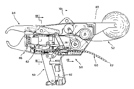
Viewing now figure 6 as a whole, it can be seen that
apparatus 50 includes: a mechanism 80 that feeds and
pulls the indented strap 52; a mechanism 82 that guides
the indented strap 52 and cuts and separates a retaining
element 62 from strip 60 pairing it with indented strap
52; a closing device 84 which completes the guiding
channel for the indented strap 52 around a bundle of
cables to be bound; mechanism 86 for cutting the
serrated strap 52; a mechanism 88 which operates the
mechanism 84, causing the advance of guiding mechanism
82 and of strip 60 of retaining elements 62.
The group of mechanisms 80, 82, 84, 86, 88 are
appropriately enclosed in the housing of the apparatus
50 usually made up of two half shells 90 and 92 (fig. 7)
which are approximate mirror images and to which plates
94 and 96, that are also approximately mirror images,
are fixed; the two plate-support mechanisms 80, 82, 84,
1;~9~3 ~4
86 and 88. and provide a running guide for strap 52 and
strip 60.
The two half shells 90 and 92 of the housing 50 support,
in the rear, a pair of arms 98 placed side by side which
hold the reel of serrated strap 52 as shown in figure 6.
Mechanism 88 that operates the apparatus, as better
shown in figure 8, includes a lever 100 pivoted around
pin 194 and linked by element 102 to two paired levers
lQ4 pivoted around pin 106 attached to plates 94 and 96.
Levers 104 are attached, through a slot and by means of
pin 108, to a carriage 110 running inside a guide worked
into plates 94 and 96.
Levers 104 are also connected, by means of pins 112, to
connecting rods 114 that are connected, through pins
116, to lever 118 which, in turn, rotates around pin 120
fixed across plates 94 and 96 and is connected to
closing mechanism 84, as explained further on.
On carriage 110 there is a rocking lever 124 held
upright by spring 126.
Lever 124 fits into recess 134 of mechanism 82 to
provide a forward push to mechanism 82 itself.
On top of lever 100~ there is an elastic tooth 128,
which pushes forward the strip 60 of retaining:elements
16 ~Z9~313 ~
as will be explained later.
Inside the two half shells 90 and 92, in the portion
that forms the hand-grip, there is an electric push-
button switch 130 triggered by .lever 100.
Lever 100 is held in the normal position of figure 8 by
the outward push exerted by spring 132.
Mechanism 82, which guides the indented strap 52 and
which positions each retaining element 62 on the forward
end of strip 60, is better shown in figures 9 and 10.
Mechanism 82, includes carriage 136 which runs inside a
guide, not shown, worked out of plates 90 and 92.
Above the carriage 136, there is a channel-shaped
element 131 (figure 10) which protrudes from the
carriage 136 and terminates with a kniFe-like cross lip
214 and with convex outmost edges 133 oF the side walls
to fit convex face 68 of retaining elements 62, as it
will be explained later. The channel element 131 of the
carriage serves many functions and,in particular, aside
from cutting and positioning the retaining elements 62,
it retains a sliding rod 138 provided with a side arm
138a protruding from one side of channel 131 through a
wider opening 35 for activating a microswitch 140
located on the same side of carriage 136.
17 ~L2~93~
Toward the back of opening 135, the side walls of
channel element 131, have openings 137 opposite to each
other for engaging the end heads 142a and 144a of -two
flexible steel bands 142 and 144 which run along
guides worked out inside plates 90 and 92 and serve the
purpose of guiding the indented strap 52 from the
feeding mechanism 80 to carriage 136.
Above guiding bands 142 and 144, inside channel element
131, there is a covering rod 146 provided with lateral
wings 146a and 146b set at the proper distance for
fitting into openings 137 and 139 on the side walls of
the channel 13; the front end of covering rod 146 has
its upper face slanted to form a sharp edge 220 which
protrudes out of the outermost edges of the side walls
of channel 131.
On both sides of carriage 136 there is a roller 148
supported by pin 146.
Closing mechanism 84, as shown in figure 8, has a
movable upper jaw 150 and a lower fixed jaw 151, with
the ends curved toward each other so as to form two
guides 210 and 211 which together define a,n annular
channel for guiding the indented strap 52 around a
bundle of cables. The upper jaw 150 is freely pivoting
18 ~99~
around pin 120 of lever 11~ which is provided wi-th a
protruding arm 118b connected to a return spring 122
hooked to the back extension of movable jaw 150. A
counter-acting lever 196 is pivoted at 195 on the front
arm 118b of the lever 118, said lever 196 having its
front end 196a pointed and turned downwards in the
direction of guiding channel 211 inside moYable jaw 150:
a spring 198 is disposed between the protruding end o-F
front arm 186b and counter-actiny lever 196.
Mechanism ~6, for cutting the indented strap 52, better
shown in figures 9, 11 and 12, includes a knife 152
which runs vertically inside plates 94 and 96 with
motion imparted by two parallel and opposing rocking
levers 154 that turn around pin 156 and provided, at the
forward end, with a slot that engages pin 158 of knife
152; two pulling springs 160, attached between levers
154 and the shells of the apparatus pull levers 154 and
knife 152 downward. ~nife 152, as better shown by
figures 11 and 12, has a V-shaped profile for cross~
cutting the indented strap.
Mechanism 80, for feeding toothed band 52, as better
shown in figure 10, includes a low voltage d.c. motor
162 connected, through pulley 164 and toothed belt 166,
1 9 ~;~9~3~
to pulley 170 o~ reducer 168. The reducer has an
additional toothed pulley 172 connected by toothed belt
174 to a toothed pulley 176 which drives two discs 180
with edges shaped in the form of teeth to feed indented
strap 52 along plane 190 inside of plates 94 and 96, in
correspondence with guiding channel 206 to th~ back
inlet of serrated strap 52; reducer 168 and the indented
discs are held by a rocking p1ate 178 which pivots
around the axes of the discs and is acted upon by a
compression spring 182 placed between a protrusion
222 of the plate and a setting screw 184.
Motor 162 may be of any type such as a motor`driven by a
fluid under pressure connected to the toothed discs by
means of mechanical driving elements.
As shown in figure 14, which is an exploded view of
figure 13, lever 186 for the disengagement of rocking
lever 124 acts with its back arm against protrusion 224
of rocking plate 178 while, at the other end, lever 124
has a protrusion 187 that can place itself under a rear
pin of rocking lever 124; spring 188 is placed
underneath release lever 186.
In general, and according to this invention, a plastic
indented strap, in the form of a continuous band is made
~ Zg ~ 3 4~
to advance along a gu-iding channel by initially
passing its end through a curved side of a pre-
positioned retaining elernent, after having opened up one
of its toothed arms for allowing the free advance of the
binding strap which moves with its indentation facing
outward until it wraps the cable bundle. The binding
strap, after completing its turn, is reintroduced with
its end into the retaining element through the flat side
opposite the preceeding one while the elastic arm is
released and the strap is stretched so that the teeth of
both arms engage with the teeth of the binding strap. At
the same time the indented strap is cut in
correspondence with the retaining element.
Referring to Figures 6, 7, 8, 9, 10, 13, 14, 15, 16 and
17, it should be clear how the automatic apparatus 50
performs the binding of a bundle of cables.
Strip 60, made up of many retaining elements 62, as
figure 14 shows, is inserted by the operator into
guiding channel 200 and is pushed until it stops at
202, while spring 204 keeps strip 60 from backing up.
The operator inserts band 52, as shown in figure 14,
into guiding channel 206 until it becomes engaged under
the teeth oF serrated discs 180.
~'
2 1 ~Z~33~
The apparatus is ready to operate once strip 60 and
band 52 have been positioned.
When a bundle of cables is positioned within working
area 208, by pressing lever 100, the lever 106 will
rotate sequentially.
As lever 106 rotates, carriage 110 advances and lever
114 lifts.
Carriage 110 will cause the carriage 136 to advance by
means of rocking lever 124 as engaged by recess 134.
When lever 114 lifts, lever 118 will rotate around pin
120.
As lever 118 rotates it will pull behind, by means of
spring 122, the jaw 150 which lowers and closes the
binding area whi le channels 210 and 211 will come into
contact to provide a continuous guide for band 52.
The rotation of lever 118 and, hence, the closing of
jaw 150, will lower lever 196.
As carriage 136 advances while pushed by carriage 110,
cam 154b of lever 154 becomes disengaged.
As lever 154 lifts under the action of springs 160,
knife 152 lowers.
The advance of carriage 136 and the lowering of knife
152 are synchronized so that, as carriage 136 advances,
22 ~g93 ~4
knife 214 cuts the pl~stic portion 64 while an element
62 becomes separated and transferred, through the action
of convex ends 133 of channel 131 (figure 16) into a
mating position 226 (figure 14) with band 52.
As carriage 136 advances, as it is pushed by lever 124,
it pulls the flexible steel elements 142 and 144 which
run inside the yuides of plates 94 and 96.
It is the function of the flexible elements 142 and 1~4
to provide a continuos guiding channel for the band 52,
which would otherwise be interrupted, from the position
of carriage 136 when it is completely drawn in at rest,
to its all-advanced position during operation.
Element 62, when pushed into position 216, lifts and
then lowers lever 196 which is used to hold element 62
in position with its pointed end 196a; when lever 100
reaches the end of its strake it activates microswitch
130 which, in turn, sets motor 162 into motion.
As motor 162 turns clGckwise, as shown in figure 14, its
motion is transmitted to reducer 268 by means of
toothed belt 170. Reducer 170 transmits its motion
through toothed belt 174 to the toothed wheels 180 with
enough torque for pushing and then drawing band 52 so as
to achieve the binding of the bundle of cables.
23 ~Z9~3~g
The opposing teeth of toothed wheels 180 engage the
teeth of strap 52 while the toothed wheel which pushes
the line of teeth 54 of band 52 move it along channel
218 and through the channel of carriage 136.
Carriage 136, while bringing element 62 into position
216 by means of tip 220 of element 146, causes the
bending portion 70 of element 62 to lift, as seen in
figure 17, so that the indented strap runs freely
through the central seat of element 62 and along channel
210 of binding area 208; the indented strap runs until
its end reaches element 62 as it runs again, in the
opposite direction, through the central seat of element
62 and stops against part 138 while engaging the teeth
of portion 72 of element 62 as shown in figure 11.
After having completed its turn around the bundle of
cables, the tip of band 52 hits the front end of element
138 and pushes it backwards causing the intervention of
microswitch 140.
When microswitch 140 is turned on, motor 162 reverses
direction and, hence, toothed wheels 180 turn in the
opposite direction as well.
Toothed wheel 180 with its teeth engaged for the
reversal of motion to the line of teeth 56 of strap 52,
~29~3~
24
pulls the strap so as to obtain the binding as shown in
figure 12.
As it appears frsm figure 16, the binding action causes
the partial opening of jaws 150 and 151 so that, as jaw
150 rotates around pin 116 it moves upward allowing the
bundle cables to gather against retention element 62.
The opposing force due to the binding action, while the
motor 162 is still turning, causes an anticlockwise
rotation of rocking plate 178, as shown in figure 15.
The pull exerted by the movement of rocking plate 178,
brings element 222 against spring 182 and determines the
tension of the binding.
By adjusting the screw 184, the binding tension can be
set to the desired value.
As rocking plate 178 ~figure 16) rotates, element 224
forces lever 186 to move down.
Lever 186, in turn, causes lever 124 to move downward.
As lever 124 moves down, carriage 136 becomes disengaged
and due to the pull exerted by spring 226, resumes its
rest position leaving the binding portion 70 free to
engage the teeth of strap 52.
Carriage 136, on its back travel, sets lever 154 into
motion by means of rollers 148. Levers 154 lift the
- 25 ~Z~3 ~
knife 152 which, because of its profile (figures 11 and
12 ) cuts a V-shaped groove into serrated strap 52 that
offers its notches to the next cycle.
The V grooves in strap 52, because the motor is still
turning, pull the band causing the return of the rocking
plate and the motor to stop.
When the operator releases lever 100 which is pushed by
spring 132, levers 102,106,110,114 and 118 return to
their position and jaw 150 opens completely so that the
completed binding is made free for removal.
When lever lO0 is automatically released because of
mechanism 128, strap 60 is pushed upward thùs preparing
a new retaining element 62 for the next binding cycle.
A ratchet element 228, as shown in figures 13 and 15,
acts in such a way that when lever 100 is pressed, at
the start of a new cycle,it remains in this position
even if the operator does not keep it pressed, in as
much as lever 104 is prevented from rotating~
This way the cycle has to perform all of the steps
required for a complete binding.
Lever 100 is released the moment the rocking plate 190,
by means of its protruding part 224, presses upon lever
186.
~ ~ 9 ~ 3
2fi
Upon the release of lever 100 the operator, because of
the push exerted by spring 132, is made aware that the
working cycle is being completed.
A microswitch, not shown in the attached drawings, is
turned on by rocking plate 190 to a position of total
pull of band 52.
Turning on the microswitch produces a signal that will
bring motor 162 to a halt.
The automatic binding apparatus may be powered by a
supply unit with rechargeable batteries which makes it
possible for the apparatus to be used where
electrical power is not available. The automatic
apparatus may also be fed by a supply unit connected
to the network so that it may be used
uninterruptedlly.