Note: Descriptions are shown in the official language in which they were submitted.
5~
1 VIBRATION DAMPER AND ISOLATOR
BACKGROUND OF THE INVENTION
1. Field oE the Invention
The invention relates to the field of vibration
isolation and more particularly to vibration damping and
isolation for devices having extremely low vibration
specifications.
2. Description of the Prior Art
Reaction wheel assemblies on pointing control
systems are crucial elements of a telescopic system. These
assemblies, however, significantly contribute vibration
components to the system during operation. Since telescopes
have stringent pointing requirement~ there is a need to
isolate the vibration induced by the reaction wheel, most
significantly of which are caused by the axial forces
attributable to the bearing of the ball on the inner and
outer races and imperfections in the ball itself.
One prior art solution to the problem, known as a
wire rope, utilizes several stranded wîres wrapped in a
circle and attached at one end to a base or ground and at
the other end to the device or payload to be isolated.
Compliance and isolation are provided by the flexibility of
the wire and Coulomb damping or energy absorption i~ provided
by the wires rubbing together. This device has several short
coming which include, low damping and stiffness
characteristics which are variable with the magnitude of the
input vibration level, performance changes with environmental
~2~
1 variations, and mathematical complexities that require an
iteration procedure of design and test before reaching a
final configuration.
A second solution of the prior art utilizes
viscoelastic materials as the isolating element. These
devices though capable of providing isolation for most
applications, exhibit excessive sensitivity to temperature
and other environmental conditions.
SUMMARY OF THE INVENTION
In accordance with the present invention vibration
isolation and dampiny is achieved with an arrangement of
bellows, coil spring, and fluid which eliminate rubbing
surfaces, thereby Coulomb forces, and provide a stiffness
that i5 independent of the vibration level. Firs-t and seeond
bellows are positioned in axial alignment and fluidly sealed
at opposite ends by an end piece and base respectlvely to
form inner chambers. A shaft extending along the common axis
i~ attached to the end piece and base to maintain a fixed
ZO separation distance therebetween. A piston having an axial
bore hole and a flange extending therefrom for coupling to a
payload is positioned about the shaft in a coaxial
relationship, forming a fluid gap between it and the shaft.
This fluid gap couples fluid chambers in the first and second
bellows that are formed between the piston, the inner walls
of the bellows, and the flange extension from the piston to
which the previously unsealed ends of the bellows are sealed
to provide for fluid containment. This arrangement obtains
damping by purely viscous fluid shear forces and completely
--2--
1 avoidR any rubbiny surfaces, thereby eliminating Coulomb
forces. The fluid i5 sealed in the two fluid chambers and
the gap formed between the piston and the shaft. As the
payload moves, the volume of one chamber increases while the
volume of the second decreases. The overall volu~e, due to
the fixed distance between the end piece of the first bellows
and the base piece of the second bellows maintained by the
shaft, remains constant. Thus, fluid of constant volume ~hat
is contained within the two chambers and the gap is
distributed to the chambers in accordance with the movement
of the load. Damping coefficients for the invention vary as
a function of fluid viscosity and the radial lenyth of the
gap, increasing as the viscosity increases and the radial
length decreases. A spring externally coiled about the
bellows supports the flange and provides stiffness to the
vibration isolator.
Temperature compensation may be achieved by
providing a third bellows which is axially aligned with the
first and second bellows, and has a fluid chamber therewithin
coupled to the fluid system of the first and second bellows
to provide for the e~change of ~luid between the temperature
compensator and the main vibration isolator. This fluid
e~change causes a constant fluid pressure to be maintained in
the system with temperature variations. A spring externally
coiled about the temperature compensating bellows maintains
an axial force thereon to achieve a positive pressure on the
internal fluid over the temperature range of interest
independent of the environmental pressure.
?5~3Z
72558~16
The vl~ratlon lsolatlon and damplng apparatus of the
inventlon has a first bellows, one end of whlch is fluldly sealed
by an end piece and a second bellows coaxlally allgned with the
first bellows, one end of whlch ls fluldly sealed by a base plece.
A shaft of predetermined length ls coupled to the end and base
pleces and is coaxlally posltloned with the flrst and second
bellows so that a flxed predetermlned separatlon ls malntalned
between the end and base pleces. A plston, having an axlal bore
coaxlally posltloned wlth the shaft, has a flange extenslon that
ls coupled to the open ends of the flrst and second bellows ln a
manner to establish fluld seals with the first and second bellows.
Thls flange extenslon lB constructed to allow the coupling of the
apparatus to a payload~ The plston forms a flrst fluld chamber
wlth the flrst bellows and a second fluid chamber, with the second
bellow~. A fluld fllls the flrst and second fluid chamberq and a
radlal gap between the plston and the shaft provldes fluld
coupling between the chambers. Springs colled a~out the first
bellows between the flange extenslon and the end plece and coiled
about the second bellows between the flange extenslon and the base
plece provlde radlal and a~lal stiffness. A thermal compensator
bellows wlth a fluid fllled lnner chamber ls fluidly coupled to
the radlal gap and to the flrst and second fluld chambers. A
pressure mechanism ls coupled to the thermal compensator bellows
ln a manner to establish positlv~ pressure on the fluid with
variatlons of atmospherlc pressure condltions. The thermal
compensator bellows expand~ wlth expansion of the fluld and
cooperates wlth the pressure mechanlsm to malntaln constant system
pressure.
3a
B
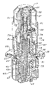
1 BRIEF DESCRIPTION OF THE DRAWINGS
Figure 1 i5 a cutaway view of a vibration damper
and isolator, including a temperature compensatlng element,
constructed in accordance with the principles of the
invention.
Figure 2 is a schematic diagram of the vibration
damper and isolator of Figure 1.
DESCRIPTION OF THE PREFERRED EMBODIMENTS
The invention will be describecl with respect to
Figure 1. A vibration damper and isolator 10 includes a
cover 11 enclosing a upper bellows 13 with an end piece 15
bonded at one end to provide a fluid seal and structural
integrity. A lower bellows 1~ with a base piece 19 bonded to
one end, also to provide a fluid seal and structural
integrity is positioned in axial alignment with the upper
bellows. Each bellows may have a wall thickness o~ 75
micrometers and may be electroplated. A rigid shaft 21,
coaxial with the upper and lower bellows, is bonded to the
end piece 15 and the base 19 to maintain a fixed distance
therebetween and thereby, a constant volume within the
bellows assembly. A piston 23, having an axial bore and
flange 25 extending therefrom, is coaxially positioned about
the shaft 21 to create a radial gap 27 therebetween. The
section of the upper bellows opposite the end piece is bonded
to an upper surface 29 of the flange extension of the piston,
while the section of the lower bellows opposite the base
piece 19 is bonded to a lower surface 31 of the flange
extension. An upper fluid reservoir 33 and a lower 1uid
--4--
1 reservoir 35 are respectively formed by the upper and lower
bellows iII combination with the flange extension and the
outer surface of the piston wall. Fluid, which may be Dow
corning 200 Series silicone, is installecl in the system to
completely fill the reservoirs 33, 35, and the gap 27. This
fluid, during vibration, is forced between the upper
reservoir 33 and the lower reservoir 35 via the damping
gap 2~. Though the volume of the upper and lower reservoirs
33, 35 may change with the motion of the payload attached to
the flange, the total reservoir volume remains constant due
to the fixed distance maintained by the shaft 21 between the
end pièce 15 and the base piece 19. Con~e~uently, motion by
the payload and flange 25 must produce equal but opposite
volume changes in the upper and lower reservoirs 33, 35.
16 An upper stainless steel spring 3~ is coiled about
the outer surface of the upper bellows 13 between the upper
surface 39 of the flange extension 25 and a spring retainer
41 bolted -to the end piece 15. A lower stainless steel
spring 43 is coiled about the outer surface o~ the lower
bellows 1~ between the lower surface 45 of the flange
extension and a spring retainer surface 4~ formed in the
skirt 49 extending from the base 19. These springs provide
appropriate radial and axially stiffness for the vibration
damper and isolator.
Refer now to the schematic diagram of the vibration
damper and isolator shown in Figure 2, wherein elements
previously cited bear the initially assigned reference
numerals. In Figure 2 it is schematically shown that the end
piece 15 and the base piece 19 are maintained at a fixed
--5--
1 5eparation distance by a rigid shaft 21. A pis'ton 23, with
an axial bore, is coaxially positioned about the shaft 21.
Extending from the piston is a flange 25 for attachment to
the load. The upper bellows 13 is bonded to the end piece 15
and to the upper surface 29 o~ the flange extension, while
the lower bellows 17 is bonded to the base 19 and the lower
surface 31 of the flange extension. It i9 apparent from
Figure 2 that the total volume of the fluid contained betweer
the end piece 15, the base 19, the upper bellows 13 and the
lower bellows 17 is constant. Assume an upward force is
exerted on the base 19, decreasing the volume of the lower
reservoir 35. Thi~ causes the volume of the upper reservoir
33 to increase and a fluid flow through the damping gap 27
from the lower reservoir 35 to the upper reservoir 33,
equalizing the forces on the upper and lower surfaces of the
flange extension, thereby causing the flange to remain
stationary.
Referring again to Figure 1. Temperature
compensation for fluid volume variation with temperature is
provided by coupling thermal compensator bellows 51 through
relief gap 53 and fluid channel 55 to the upper bellows 13.
The thermal co~pensator bellows 51 is fluidly sealed by a cap
57 and the internal region of the bellows 51, the thermal
compensator relief gap 53 and the relief channel 55 are
filled with fluid to eliminate all air gaps in the system.
An "0" ring 58 between the thermal compensator bellows 51 and
the upper bellows 13 completes the fluid seal. Fluid
expansion due to a temperature increase causes the thermal
compensator bellows 51 to expand, thereby relievin~ an over
--6--
1 pressure condition in the reservoirs 33, 35 and damping gap
2~ of the vibration damper and isolator to maintain constant
system pressure.
An axial force is maintained on the thermal
compensator bellow~ 51 by a stainless steel preload spring 59
~ to establish a positive pressure on the internal fluid over a
wide range of atmospheric pressure conditions. Spring 59 is
held in place by a lower retainer 61 coupled to the cap 57
and bolted to the spring retainer ~1 and an upper retainer 63
extending for a predetermined distance above the lower
retainer and also bolted to the spring retainer 41.
While the invention has been described in its
preferred embodiments, it is to be understood that the word~
which have been used are words of description rather than
limitation and that changes may be made within the purview of
the appended claims without departing form the true scope and
spirit of the invention in its broader aspects.
-7-