Note: Descriptions are shown in the official language in which they were submitted.
~300~3
LINE STORAGE CONTAINER
TECHNICAL FIELD
This invention relates to a storage container for
flexible, elongated lines, and particularly those having a
bulky object on one end thereof, such as fishing lines,
electrical extension cords, automobile jumper cables, and
so forth.
BACKGROUND ART
Storage of elongated, flexible lines such as fishing
lures with leaders, electrical extension cords, automobile
jumper cables, tow ropes, and so forth, have created
problems prompting a variety of proposed solutions which
have met with mixed success.
Spools of various types have been used to store
lines in certain applications, but unique storage problems
arise when one or both ends of the line contains a bulky
- 1 -
1301)~3
object such as a fish hook, leader swivel, jumper cable
clamp, etc. In some spool-type containers, these bulky
ends are merely left to dangle outside the container, such
as is shown in U.S. Pat. No. 3,062,475, Miller (FLEXIBLE
CONTAINER FOR LEADERS AND THE LIKE). In other devices, the
bulky end is hooked in an aperture on the outer portion of
the device, such as in U.S. Pat. No. 4,200,249, Synstelien,
et al. (STORAGE DEVICE), and U.S. Design Pat. No. 273,410,
Tomosy (COMBINED FISH HOOK AND LINE DISPENSER AND STORAGE
CONTAINER). Similarly, U.S. Pat. No. 2,743,546, Crist
(LEADER-KEEPERS) shows a rectangular~shaped spongelike
device where the leader hook is embedded in the sponge
material.
U.S. Pat. No. 3,991,507, Bart (COLLAPSIBLE ORGANIZER
RECEPTACLE FOR FISHING LEADER) shows a generally
cylindrical, accordion-like device which includes apertures
in the accordion folds into which a fish hook may be
lodged, allowing the line to be wrapped around the
accordion fold crease. Each crease may hold a separate
leader/hook, and the device may then be collapsed and
placed in a shell which retains the accordion in the
compressed state.
The above devices all are somewhat complicated from
a manufacturing standpoint and/or in actual use. Also,
devices which have the fish hook on the outside,
~ - 2 -
~300~3
such as Sy~.stelei~ a~.d ~mller are ~ul.~era~le to
tangling pro~le~s 2~d may r.ot a~ecuately shield the
hook. rurther~.ore none of these ~evices provide for
protected storaqe of bul~y lures (as oppose~ to
single, ge~erally flat fish hooks).
BRIEF SUMMARY OF THE INVENTION
According to the invention, a storage container for
a flexible, elongated line having a bulky member on one
end thereof, comprises a spool having a first cylinder of
relatively short length with first and second ends; first
and second flanges extending radially outwardly from the
first and second cylinder ends respectively; and wall means
extending substantially across the first cylinder end,
defining with the cylinder a storage cavity. A portion of
the cylinder and the second flange have a discontinuity
whereby the bulky member may be stored within the cavity
with the line passing through the discontinuity and wound
about the spool.
The invention will now be described further by way
of example only and with reference to the accompanying
drawings.
1300~13
B~IEF DESC~I~TION O~ DR~.W-~NC-S
Figure 1 is a pers~ective view of a device of
the invention;
Figure 2 is a plar. view of a device of the in- -.
venticn;
Fisure 3 is a cross-sectional view of Figure 1
taken alor,g line 3-3 tnereof;
Figure 4 is a side-partially broken away view
of.a modified embodiment of the invention;
Figure 5 is a plan view of an alternative em-
bodiment of the invention;
Figure 6 is a cross-sectional view of Figure 5
taXen along line 6-6 thereof; and
Figure 7 is a plan view of an alternate embodi-
ment of the in~iention.
. - 3a -
~30()1~3
BEST MODE FOR CARRYING OUT THE INVENTION
A storage container according to the invention
may be manufactured in a variety of sizes to accommo-
date a variety of physical objects. Two preferred
applications are described below, namely, storage of
fishing lines and jumper cables. It will be under-
stood, however, that the invention may be adapted to
other suitable applications such as tow ropes,
electric extension cords, and so forth, by enlarging
or reducing the size of the container appropriately.
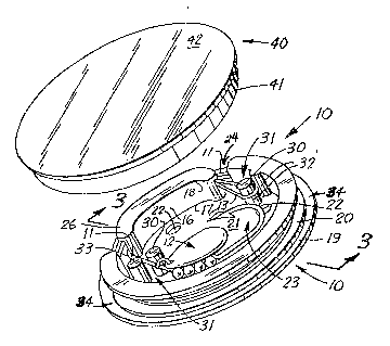
Referring to Figures 1-3, a preferred container
adapted for storage of fishing lures is depicted. In
this application, the container is particularly suited
to storage of jigs and other bulXy lures which
typically include one or more hooks with associated
structure such as spinners, stops, sinkers, bobbers,
and so forth. Often, the components of the lure are
permanently tied to a leader which may be anywhere
from a few inches to several feet long. The leader
may be standard monofilament fishing line, nylon,
teflon, or even steel.
A preferred container suitable for storage of
such fishing lures includes a spool tlS) comprised of
a cylinder (16) of relatively short length measured
from its first end (17) to its second end (18). The
cylinder includes first and second flanges (19) and
1300~
(20) respectively, carried by the first and second ends
(17) and (18) respectively, of the cylinder (16). The
flanges extend radially outwardly of the cylinder t16) and
define an annular channel (34) for receiving the line
(11). The cylinder (16) and second flange (20) include at
least one discontinuity (24) to allow the line (11) to pass
radially inwardly from the annular channel (34) into a
storage cavity (23). The cavity (23) is defined by the
cylinder (16) and a wall (21), which extends substantially
across the first end (17) of the cylinder (16). The
discontinuity (24) in the cylinder (16) need not extend the
entire length of the cylinder (16) (the length being
defined with reference to a longitudinal axis of the
cylinder (16)). The discontinuity (24) should extend for
at least a portion of the combined length (L) of the
cylinder (16) and second flange (20) however, to permit
passage of the line (11) into the storage cavity (23).
The outer surface (25) of the cylinder (16) may
include a radially inwardly tapered portion (26) adjacent
one or both sides of the discontinuity (24), providing
relief for that portion of the line (11) entering the
storage cavity (23), thereby preventing unnecessary stress
and/or kinking of the line (11).
- 5 -
1300~1~
Preferably the spool (15) includes means defining a
slot (31) located radially inwardly of the cylinder (16)
proximate the discontinuity (24) for securing the line (11)
within the storage cavity (23). Desirably, the slot means
(31) is defined by two opposed convex surfaces (32). Such
surfaces avoid sharp corners and reduce the likelihood of
damage (such as abrasion and kinking) to the line (11).
The width of the slot (31) should be larger, but not
substantially larger, than the diameter of the line (11).
For lines (11) that are particularly stiff (e.g., steel
leaders and jumper cables), the slot (31) may be somewhat
wider without losing its effectiveness.
In a preferred embodiment, the convex surface is
defined by a post (30) extending from the wall (21)
generally parallel to the cylinder ~16). Desirably, the
post (30) is approximately the same length as the length
(L) of the cylinder (16), thereby preventing the line (11)
from slipping out of the slot (31). The slot may be
defined by one such post (30) and the cylinder (16) itself,
or by a post (30) and a second partial post or convex
surface (33) extending radially inwardly of the cylinder
(16), as shown in Figures 1 and 2. Alternately, the slot
(31) may be defined by two or more such posts (30).
1300~13
.~ltho~gh not strictIy necessary in scme a?~
catior.s cr the inver.tion, ~esirably a ccver (40) is
also prcvided to assist in retaining the bulXy membe~
(12) within the storage ca~ity (23), and further to
protect the line (11) wrap~ed about the spool (15).
Desirablv the cover incluàes a seco~d cylinder (41)
havir.g a length su~stantially equivalent to or
slightly larger than the length (~) of the spool
cylinder (16), the cover cylinder (~1) having an
internal diameter approxi~ately equ2l to the outside
diameter of one of the flanses (19) and (20) of the
s~ool (15). When used with a cover (~0), perforations (22)
in either the cover (~0) or the ~all (21) of the s~ool
(15) may be provided to facilitate ventilation of the
container. Ventilation may De desirable when fishing
lures are stored, thereby allowirg the lure to dry out
between uses.
Desirably the length (L) of the cylinder (16)
is substantially less than the diameter (D) of the
cylinder (16); preferably the diameter (D) of the
cylinder is at least about three times the length (L)
of the cylinder (16).
In use, referring to Figure 1, a fishing lure
or similar bulky member (1~) may be placed in the
storage cavity (23) of the container (10). The line
(11) is passed through the slot (31), through the
13001~
discontinuity (24), and then is wrapped about the outer
surface (25) of the cylinder (16). The other end of the
line (11) then is strung through a discontinuity (24) and a
slot (31) into the storage cavity (23), thersby securing
the line and lure within the container (10).
Although the embodiment depicted in Figures 1-3
includes two discontinuities (24), a single discontinuity
(24) with a pair of slot means (31) would also suffice.
Desirably the slot means (31) is positioned proximate the
discontinuity (24) in a position which will tend to avoid
excessive stress, bending or kinking of the line (11).
Preferably the slot (31) is located along an arc generally
tangent to the outer surface (25~ of the cylinder (16), the
arc having a radius less than the radius of the outer
surface (25) of the cylinder (16) and coinciding generally
with the arc of the line (11) as it passes through the
discontinuity (24).
In certain applications it may be desirable to
provide shoulders (28) adjacent the discontinuity (24) in
the cylinder (16) and second flange (20) to prevent
windings of the line (11) from entirely occluding the
discontinuity (24), thereby assuring low stress entry
~ - 8 -
1~0011~
of the end (13) of the line (11) through the discontinuity
(24) into the storage cavity. This feature may be
particularly useful in embodiments designed for storage of
lines which are relatively long and thick, such as jumper
cables. It is also desirable if the cover wall ~42) abuts
the second flange (20) of the spool (15), as shown in
Figure 4, and if the second flange (20) is of relatively
small thickness; the shoulders assure proper seating of the
cover (40) without compressing the windows of the line (11).
Figures 5 and 6 depict another application of the
container of the invention, namely storage of automotive
jumper cables. The structure of the device may be
substantially similar to that previously described, except
on a somewhat larger scale, e.g., an o~er-all diameter in a
range of 12-24 inches. Because jumper cables (14) tend to
be relatively thick and somewhat stiff, particularly in
very cold weather, the slot means (31) may be substantially
larger or omitted entirely, the bulk of the jumper cable
clamps and the resilient stiffness of the cables (14)
serving to retain the ends of the cables (14) within the
storage cavity (23). Multiple discontinuities (24) may be
provided, as shown in Figures 5 and 6, to reduce the
average amount of cable stored within the storage cavity
(23) for any given length jumper cables.
13001i3
The cover (40) generally is not necessary in this
application.
In various applications of the present invention it
may be desirable to further include flange portions (27)
extending generally radially inwardly from the second end
(18) of the cylinder (16) to assist in retaining the line
(11) and bulky member (12) within the storage cavity (23).
See Figure 7. This feature may be particularly useful for
lines which are somewhat resilient, i.e., they tend to
resist curvature and therefore resist retention in the
storage cavity, particularly if a length of line
approaching the circumference of the cylinder (16) must be
stored within the cavity (23). Where more discontinuities
(24) are provided in the cylinder (16), however, generally
less line (11) will have to be stored within the cavity
(23).
While a preferred embodiment of the present
invention has been described, it should be understood that
various changes, adaptations and modifications may be made
therein without departing from the spirit of the invention
and the scope of the appended claims.
- 10 -