Note: Descriptions are shown in the official language in which they were submitted.
130~)~L82
APPARATUS AND METHOD FOR EFFECTING
MOVEMENT OF SELECTED TIERS OF STACKED
ARTICLES USING PRESSURE DIFFERENTIALS
Field of the Invention
This invention relates to apparatus and method
for movement of articles stacked in tiers, and, more
particularly, relates to apparatus and method for
movement of selected tiers of stacked articles using
pressure differentials.
Backqround of the Invention
Lifting devices for elevating stacked articles
employing a support member inserted beneath the
articles to be lifted, as, for example, using
forklifts for elevating palletized loads, are well
known and have been heretofore suggested and/or
utilized. Additional examples of stacked article
lif~ing devices can be found in U.S. Patent Numbers
3,522,890, 3,643,822, and 3,884,366.
Devices for elevation of a single layer of
articles employing vacuum cups, magnetic heads and
the like are also well known and such devices have
heretofore been suggested and/or utilized for the
arrangement of articles into desired loads tsee, for
example, U.S. Patent Numbers: 4,242,025, 3,780,884,
3,757,966, 4,252,497, 4,566,836, 3l859,772,
3,836,017, 3,544,410, 3,682,290, and 3,300,065.
.~
,
Q , , .~ ;
.,
~3~0~L8~
Various palletizing and depalletizing devices
employing pllsh cylinders, bulkheads, clamps and/or
tilting mechanisms have also been heretofore
suggested and/or utilized for removal of articles
from, and/or placement of articles on, pallets and
the like.
While such devices now known have been found to
be acceptable for some uses, such devices have not
been found to be capable of and/or suitable for
suspending multiple layers, or tiers, of stacked
articles relative to a reference surface without the
necessity of providing a supporting member at the
bottom surface of the suspended load or high clamping
forces to the load. Moreover, no such known devices
have been capable of establishing a pressure
differential to effect suspending, or lifting, of
selected plural tiers of articles.
Summary of the Invention
This invention provides apparatus and method for
relative movement of multiple, independently movable
layers, or tiers, of articles arranged in a stack and
a reference surface upon which the tiers are resting
whereby the tiers of articles are suspended without
necessity of a supporting member at the bottom
surface of the tiers of articles by establishment of
~3~ 82
a pressure diEferential to effect suspending, or
lifting, of selected plural tiers of articles.
It is an object of this invention to provide a
method and apparatus for effecting relative movement
between a plurality of selected tiers of articles and
a reference surface having the selected tiers stacked
thereon with the selected tiers being independently
movable with respect to one another, the device
including pressure differential establi.shing means
positionable adjacent to the selected tiers of
articles, the pressure differential establishing
means including a top wall member and a plurality of
side wall members at least some of which include
movable means spaced from the top wall member, the
movable means having channeling means and sealing
means connected thereto, the channeling means
estabishing the pressure differential adjacent to
substantially all of the plurality of selected tiers
above the reference surface, and the sealing means
positioned to be contiguous to the lowermost tier of
the selected tiers of articles, and the device
further including pressure effecting means for
effecting a pressure differential within the pressure
differential establishing means, the pressure
differential being sufficient to maintain the
selected tiers of articles within the pressure
,,; . ,.,~ :
. ., ~. .
- ~3~ 82
differential establishing means without support
provided by the reference surface, and displacement
means for causing relative movement between the
selected tiers of articles and the reference surface,
the movement having a verticle component.
With this and other objects in view, which will
become apparent to one skilled in the art as the
description proceeds, this invention resides in the
novel construction, combination, arrangement of parts
and method substantially as hereinafter described,
and more particularly defined by the appended claims,
it being understood that changes in the precise
embodiment of the herein disclosed invention are
meant to be included as come within the scope of the
claims.
Brief Description of the Drawinqs
The accompanying drawings illustrate a complete
embodiment of the invention according to the best
mode so far devised for the practical application of
the principles thereof, and in which:
FIGURE lA is a perspective view of the apparatus
of this invention shown in connection with a pallet
ready for insertion at a desired position;
FIGURE lB is a front view of the control panel
shown in FIGURE lA.
.
FIGURE 2 is a perspective view of the apparatus
of this invention, as shown in FIGURE lA,
illustrating operation of the apparatus for insertion
of a pallet between tiers of articles to create two
stacked half loads of articles on two pallets;
FIGURE 3 is a front sectional view taken through
lines 3-3 of FIGURE lA;
FIGURES 4A and 4B are partial side sectional
views taken through lines 4-4 of FIGURE 3
illustrating different operational positioning of the
device for suspending tiers of articles;
FIGURE 5 is a sectional view taken through lines
5-5 of FIGURE 3;
FIGURE 6 is a schematic illustration of fluid
flow and resulting pressure differential and lift
experienced in operation of the device of FIGURES 3,
4A and 4B;
FIGURES 7A and 7B are partial front views of the
apparatus, as shown in FIGU~E 2, illustrating a
second arrangement for separating tiers of stacked
articles for insertion of a pallet therebetween
employing pneumatic balloons for raising and lowering
the reference surface;
FIGURE 8 is a side sectional view taken through
lines 8-8 of FIGURE 7A;
~3~0~B2
FIGURE 9 is a partial front view of the
apparatus shown in FIGURES 7A, 7B, and 8 illustrating
intermediate inflation of the pneumatic balloons for
pallet insertion at the reference surface;
FIGURE 10 is a side sectional view taken through
lines 10-10 of FIGURE 9;
FIGURE 11 is a perspective view o~ another
embodiment of the apparatus of this invention;
FIGURES 12A and 12B are side sectional views
taken through lines 12-12 of FIGURE 11 illustrating
different operational positioning of the embodiment
of the apparatus of FIGURE 11;
FIGURE 13 is a perspective vi~w of a third
embodiment of the apparatus of this invention
particularly illustrating a means for insertion and
removal of slip sheets beneath a suspended load;
FIGURES 14A and 14B are partial side views of
the embodiment of the apparatus shown in FIGURE 13
illustrating removal of a slip sheet; and
FIGURES 15A and 15B are flow diagrams
illustrating methods for achieving desired loads
using the apparatus of this invention.
Description of the Invention
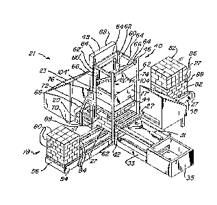
Apparatus 21 is shown in FIGURE lA for achieving
relative movement of selected tiers of stacked
articles each tier being independently movable and
s , , ,
~3~82
having multiple rows of multiple art:icles, and a
reference surface on which the selected tiers of
articles are stacked, which reference surface can be,
for example, a lower non-selected kier of articles or
a pallet upon which the articles are stacked, wi-th
relative movement being effected, for example, to
arrange the articles into desired loads. As shown,
apparatus 21 includes pallet magazines 23 and 25 for
ejection of pallets (for example pallet 27), onto
conveying units 29 and 31. Pallet magazines 23 and
25 may eject, for example, customer pallets for
insertion into a load (as shown in FIGURE 2) or for
replacement of in-house pallets. For example, in-
house pallets 27' may be replaced at the bottom of a
load, with the in-house pallet being conveyed away on
conveyor 33 to pallet stacker 35.
As also shown in FIGURE lA, suspending device ~o
is positioned above work surface 42, and includes an
open bottomed, partial enclosure 44 maintained within
elevator framework 46 adjacent elevator 48. Partial
enclosure 44 has a high pressure air pump, or blower,
50 mounted on the top thereof for reducing the fluid
pressure within enclosure 44 through duct 52 to
create a lower pressure, or partial vacuum, within
enclosure 44.
I~,r,
:d~ ~
,
~L300~ 512
Conveyinq section 53 intersects conveyor
sections 29 and 33 (at a right angle as shown in
FIGURES lA and 2) and forms a part of continuous
conveyor 54 having a product delivery section 56 and
a product removal section 58. Control panel 59, as
best shown in FIGURE lB, is provided for selective
control of operations as described hereinafter.
While manual switching is illustrated herein, it is,
of course, to be understood that automatic, or semi-
automatic, operation could be effected by automatic
event sequencing using a timed controller, or
computer, in conjunctio~ with positioning and/or
motion sensors and associated timing devices.
As illustrated in FIGURE 2, partial enclosure 44
is vertically movable within elevator framework 46 on
elevating mechanisms 60 and 60' of elevator 48.
Elevator framework 46 includes front vertical
structural members 62 and rear vertical structural
members 62' connected at the upper portions thereof
by cross members 64. Brace members 66 further
stabilize framework 46. Vertical structural members
62' are anchored, for example by welding or bolting,
to elevator housing 68 which is attached to elevator
housing stand 70 and further stabilized thereon by
brace members 72 (only one of which is shown in
FIGURE 2).
,:
~L3~ 8~
Partial enclosure 44 includes top wall 74 and
side walls 76, 76', 77 and 77', only two of which are
shown in FIGURE 2, it being understood that four such
side walls are present, the side walls being joined
to the top wall and substantially sealed thereat, for
example, by welding.
FIGURE 2 illustrates the overall operation of
suspending device 40 for altering the configuration
of palletized loads. A palletized load 78,
consisting of tiers, or layers, of stacked articles
80, is presented at work surface 42 by delivery
section 56 of conveyor 54. As shown in FIGURE 2 for
illustrative purposes, the op~ration undertaXen
thereat is the division of palletized load 78 into
half loads 82 on separate pallets 27 (which may be,
for example, customer pallets as opposed to in-house
pallets 27', as also shown in FIGURE lA, which are
normally retained in-house by the manufacturer).
Partial enclosure 44 may be lowered over a
selected number of independently movable layers, or
tiers, 84 of articles 80 (by activation of the switch
marked "LOWER" in FIG~RE lB), so that approximately
half of the tiers are encompassed within partial
enclosure 44. As more fully developed hereinbelow,
work surface 42 may, in advance, be raised (by
activation of the switch marked "INFLATE" in FIGURE
~L30~
lB). Pump, or blower, 50 is then energized (for
example, using the "OFF"/"ON" switch in FIGURE lB)
for creation of a partial vacuum within the enclosure
resulting in, as will be more fully set forth
hereinafter, a differential pressure surrounding the
tiers 84 to be suspended, thereby maintaining the
tiers within the partial enclosure.
Relative motion is thereinafter impartéd between
partial enclosure 44 and work surface 42 having a
vertical component, for example by lowering of the
work surface 42 ~i.e., activation of the "DEFLATE"
switch in FIGURE lB) and/or raising of the partial
enclosure 44 by elevator 48 (by activation of the
"RAISE" switch in FIGURE lB), and a space is created,
between bottommost tier 86 of the load within the
enclosure 44 and the topmost tier 88 of the tiers
remaining at the work surface 42 (the top of tier 88
thus providing a reference surface for the tiers
selected to be within partial enclosure 44), for
insertion of a customer pallet 27 therebetween by
pallet conveyor 31 (for example, by activation of the
"INSERT B" switch of FIGURE lB).
As may be appreciated, partial enclosure 44
could be lowered so as to enclose all tiers 84 of the
stacked load 78 for suspension of the entire load 78
and removal of in-house pallet 27' by delivery of a
~31~ 32
customer pallet 27 on conveyor 29 from magazine 23 to
work surface 42 (by activation of the "INSERT A"
switch shown in FIGURE lB) thereby ejecting in-house
pallet 27' from the work surface for removal on
conveyor 33 to pallet stacker 35.
After desired operations have been accomplished,
relative motion is reversed (for example, by
activation of the "INFL~TE" and/or "LOWER" switches
shown in FIGURE lB), bringing bottommost tier 86 to
rest on pallet 27, blower 50 :is deactivated and
partial enclosure 44 is raised and/or work surface 42
is lowered so that the half loads 82 may be conveyed
away from work surface 4~ on removal section 58 of
conveyor 54.
Turning now to FIGURE 3, a sectional view of
suspending device 40 and work surface 42 is shown.
Elevator 48 is shown to include elevating mechanism
60 (only one of which is shown and described in
FIGURE 3, it being understood that a second elevating
mechanism 60' is provided as shown in FIGURE 2)
within elevator housing 68, mechanism 60 including
elevating chain 90 on chain drive wheels 92 and 94
mounted on drive shafts 96 and 98. Shaft and wheel
94 and 98 are connected by drive belt 100 to
reversible drive motor 102 at belt pulley 103 for
reversible rotational motion of drive chain 90.
. ~ .
~3~ 32
Partial enclosure mounting fork 104 (the details
of only one of which are shown and described here and
in FIGURE 3, it being understood a second such fork
104' as shown in FIGURE 2 is provided and mounted in
a substantially similar fashion) are connected to
partial enclosure 44 at opposite side walls 76 and
76' (as shown in FIGURE 4A using bolt and nut
assemblies 105) near top wall 74.
Fork 104 is also connected to elevator chain 90
by linkage 106 which is mounted to fork 104 at one
end, for example by bolting, and to chain 90 at the
other end, for example with pins or by clamping, for
thereby imparting substantially vertical motion to
fork 104 and partial enclosure 44 upon activation of
elevating mechanism 60.
Forks 104 and 104' (shown in FIGU~E 2) are
connected by horizontal channel 107 by, for example,
welding. Forks 104 and 104' are further maintained
in a substantially horizontal disposition by
provision of guide arms 108 rotatably connected to
guide wheels 110, for example by axle 111, and also
connected to fork 104, for example by bolting arms
108 to fork 104. Guide arms 108 and wheels 110
reside within vertical fork stabilizer housing 112,
wheels 110 being maintained within vertical tracks
114 of housing 112 for thereby maintaining fork 104
~ - -
~30~l82
in a substantially horizontal disposition while fork
104 and partial enclosure 44 are being moved in a
substantially vertical direction by elevator 48.
Partial enclosure 44, as best shown in FIGURE 3,
includes top wall 74, side walls 76 and 77, and
blower 50 connected to the interior of partial
enclosure 44 by duct 52. Blower 50 includes blower
motor 120 and squirrel cage 122, with blower motor
120, squirrel cage 122 and duct 52 being mounted to
top wall 74 of partial enclosure 44 by, for example,
bolting of the elements -thereto. Blower outlet 124
may include muffler 126 for lessening blower motor
noise. Blower 50 may be usefully configured, for
example, to move 2000 cubic feet per minute of air
and to develop 2 pounds per square inch of pressure
(or, at the interior of partial enclosure 44 when
substantially sealed, to develop a -2 pounds per
square inch of fluid pressure therein).
Filter screen 128 is provided at the upper
portions of enclosure 44 to keep foreign matter from
passing through duct 52 and into blower 50, and is
mounted to top wall 74 of enclosure 44 by, for
example, mounting pins 130.
All four side walls 76, 76', 77 and 77' of
partial enclosure 44 include upper section 134 and
lower section 136, as shown with respect to side
~3~ 32
walls 76, 77 and 77' in FIGURE 3, with the upper
sections 134 of side wall 76, 76', 77 and 77' being
affixed to one another and top wall 74, for example,
by welding. Lower sections 136 are movably connected
to upper sections 134 by hinges 138, hinges 138 being
covered by sealing material 140 for maintaining a
substantially sealed, hinged relationship hetween
upper sections 134 and lower sections 136 of the side
walls of enclosure 44.
All four lower sections 136 (only three of which
are shown in FIGURE 3~ it being understood that all
four side walls include similar elements) include
channeled wall sections 142 which are discussed in
detail hereinbelow. All four of the lower wall
sections 136, as well as the related four channel
portions 142, are connected with each other by
flexible sealing strips 144 tas shown most clearly in
FIGURES 4A and 5). With the blower 50 disengaged,
partial enclosure 44 may be lowered on forks 104 and
104' by elevator 48 over palletized load 78 of
stacked articles 80, the area between opposing
channeled sections 142 being sufficient to receive
the load (as also shown in FIGURE 5).
Work surface 42 includes right angle conveying
section 53 having primary conveying mechanisms 150
(aligned with conveyor 54 in FIGURE lA), and right
14
~, . .
82
angle conveying mechanisms 152 (only one of which is
shown in FIGURE 3, it being understood that a second
such mechanism is provided as shown in FIGURE 8).
Conveying mechanisms 152 and 150 include conveying
chains 154 and 156 on drive wheels 157 and 158
mounted on drive shafts 159 and 160, respectively.
Mechanisms 150 are conventionally driven in
association with continuous conveyor 54 (as shown in
FIGURE 1). Mechanisms 152 are driven by motor 161
connected to drive shaft 159 by belt 162 over motor
pulley 163 and shaft pulley 164.
Right angle conveying mechanisms 152 are
vertically adjustable on elevating balloons 166
maintained between mechanism support plate 168 and
base plate 170 for thereby elevating work surface 42
as will be set forth in more detail hereinafter.
Conveying mechanism drive shafts 159 are mounted
through support plate 168, for example, on bearings.
Turning now to FIGURES 4 and 5, detailed views
of the lower section 136 of side wall 76, 76', 77 and
77' and channeled sections 142 are shown. As shown
in FIGURE 4A, with respect to side wall 76, lower
sections 136 of side walls 76, 76', 77 and 77'
include plate portion 173 connected to channeled
sections 142 by hinge 175 mounted, for example by
bolting, between plate portion 173 and mounting block
'; ' '': ;
, ~ .
13~
177 connected, for example by welding, to channeled
section 142. Hinge 175 is covered by a sealing strip
179 for maintaining a substantially sealed
relationship between plate portion 173 and channeled
section 142. When no negative air pressure is
established at the interior of partial enclosure 44
by blower 50 through duct 52, the components of side
walls 76 are maintained in, and/or returned to, a
substantially vertical configuration, channeled
section 142 thus maintained by spring unit 181.
Spring unit 181 includes compression spring 183
mounted around pin 185, with pin 185 being maintained
in plate portion 173 through mounting hole 187 at one
end, and through retaining plate 189 at its other
end, the pin being maintained at retaining plate 189
by nut 191. Retaining plate 189 is fastened at its
lower end to hinge plate section 193 fastened to
block 177.
Channeled section 142 includes channel outer
walls 195 and 197, with channel walls 195 and 197
being held in a spaced relationship at their outer
ends and at their center by spacer plates 199, 201
and 203, which may, for example, be welded in place,
thereby defining channels 205 and 2Q7 (as most
clearly shown in FIGURE 5). Channels 205 and 207 are
16
; ~, .. .
.
82
open at their upper and lower ends to passage of air
therethrough at openings 209 and 211, respectively.
As also shown in FIGUR~ 4A.with respect to side
walls 76 and 77', sealing strips 215 are attached to
channeled sections 142 using, for example, glue or
rivets, at channel wall 195 at the lower end of
channeled section 142, and are maintained over
retainers 217 also attached to wall 195, for example
by welding, near channel openings 211, the seals 215
extending beyond retainers 217, and defining a
substantially continuous sealing flap around the
bottom of partial enclosure 44.
Turning to FIGURE 4B, when blower 50 is
energized, the fluid pressure within partial
enclosure 44 is lowered thereby drawing channeled
sections 142 into contact with articles 80 at the
lower of tiers 84 of the stack and drawing sealing
member 215 into contact with the lowest tier 86 to be
suspended in partial enclosure 44 while yet
maintaining a space 219 below channel opening 211
between retainer 217 and tier 86. Compression spring
183 is compressed on pin 185 by the relative movement
of retaining plate 189 on pin 185.
When seal 215 is in place, side walls 76, 7G',
77 and 77', top wall 74 and bottom surface 220 of
lower tier 86 form a substantially enclosed area 222
82
extending around the tiers of articles 80 and through
channels 205 and 207 of channeled section 142 and to
space 219 between retainer 217 and tier 86.
Substantially enclosed area 222 thus defines a zone
of differential pressure within partial enclosure 44.
When tiers 84 and 86 are thus enveloped, partial
enclosure 44 may be raised, or work surface 42 may he
lowered, for insertion, for example, of a customer
pallet 27 below tier 86, the tiers of articles being
maintained within impartial enclosure 44 by the
differential pressure created within the
substantially enclosed area 222, and without
necessarily requiring high friction surfaces at
channeled section 142 or articles 80.
Upon deactivation of blower 50, the pressure
differential within substantially enclosed area 222
is allowed to equalize and compression spring 183
will return channeled sections 142 of the side walls
back into substantially vertical alignment with upper
sections 134, thereby releasing tiers 84 and 86 for
removal from the work surface.
FIGURE 6 diagrammatically illustrates the forces
created by application of the zone of differential
pressure within cubstantially enclosed area 222 and
adjacent to tiers 84 and tier 86. For example, if
blower 50 shown in FIGURE 3 is a 30 horse power
18
.
~300~2
blower, about -1.5 p.s.i. of pressure is developed
within enclosed area 222. If bottom surface 220 of
lower tier 86 has, for example, an area of 1900
inches2, about 2700 pounds of lift is developed at
the bottom surface 220 of lower tier 86 ~1.5 p.s.i. x
lsoo inches2 = 2700 pounds) upon contact and sealing
of channeled sections 142 against tiers 84 and 86
under the influence of fluid movement induced by
blower 50 through partial enclosure 44. The upward
lift thus developed has been found sufficient to
maintain a load within partial enclosure 44 during
periods of suspension when no supporting member is
provided at bottom surface 220 of lower tier 86 of
articles 80 while minimizing stresses which might
otherwise damage the articles.
FIGURES 7A and 7B illustrate that in addition,
or as an alternative, to the raising and lowering of
tiers 84 and 86 in partial enclosure 44, work surface
42 may be raised and lowered by means of pneumatic
balloons 166 by the amount necessary to create a
space between tiers 86 and 88 for insertion of
customer pallets 27 therebetween from conveyor 31, or
for conducting other operations, for example removal
of lower half 223 of palletized articles 78 and
replacement thereof with a different half load or
suspension of all tiers 84, 84', 86 and 88 for
19
13~ 2
insertion of a customer pallet and removal of in-
house pallet 27' employing conveying units 29 and 33.
Upon receipt of palletized stacked articles 78
at work surface 42, partial enclosure 44 is lowered
and balloons 66 fully inflated through supply line
224 and valve 225 (supplied, for example, by an in-
house air supply) upon activating of the "INFLATE"
switch of control panel 59 in FIGURE lB, thereby
raising conveyor mechanisms 152 above conveyor
mechanisms 150 and conveyors 29 and 33 to a position
where lowermost tier 86 of the tiers to be suspended
within partial enclosure 44 has the bottom surface
220 thereof positioned for receipt of top surface 226
of customer pallet 27 thereat, as shown in FIGURE 7A.
As shown in FIGURE 7B, balloons 166 are
thereafter deflated thereby lowering tiers 84' and 88
of articles 80 and creating a gap between tiers 86
and 88. Conveyor 31 includes cylinders 227 and 228
having shafts 229 and 230 respectively extendible
therefrom with shaft 229 being connected to pallet
plate 232 at pin mount assembly 234. Pallet mount
232 is slidable along conveyor base 236 on slide
block 238. Pallet 27 rests on pallet mount 232, with
cylinder shaft 230 having ram 2~0 upbutting pallet
27. Shafts 229 and 230 may then be extended moving
pallet plate 232 and pallet 27 into the space between
3L3 [)~82
tiers of articles ~6 and 88, shaft 229 being
withdrawn when pallet 27 is in place below tier 86
thereby depositing pallet 27 between the tiers.
Thereafter shaft 230 may be withdrawn and
another pallet 27 deposited on pallet plate 232 from
magazine 25 (as shown in FIGURE 1). Balloons 166 may
be again partially inflated (as shown in FIGURES 9
and 10), so that tier 86 is brought into contact with
pallet 27 thereby allowing tiers 84 and tier 86 to be
released from partial enclosure 44 without being
dropped and exposing articles 80 and/or pallet 27 to
damaging impacts. Enclosure 44 may thereafter be
raised, balloons 66 deflated, and the two stacked
half pallets of articles removed on tracks 150.
As shown in FIGVRES 8 through 10 wherein
suspension of the entire load above work surface 42
is illustrated, balloons 166 may be fully inflated
and partial enclosure 44 received over all tiers 84
and adjacent to in-house pallet 27', for replacement
of in-house pallet 27' by customer pallet 27. As
shown in FIGURES 8 and 10, cylinders 245, having
extendible shafts 247, may be provided below work
surface 42 mounted on mounting plates 249.
Shafts 247 may be extended by application of air
pressure through line 250 ~upon activation of the
"MIDPOSITION" switch of control panel 59 in FIGURE lB
.
i .
0~2
for example) so that, when tiers 84 are received by
partial enclosure 44, balloons 166 may be partially
deflated, or fully deflated and subsequently
partially reinflated, as shown in FIGUR~S 9 and 10,
and shafts 247 will thereby engage support arms 251
of support plate 168 and maintain mechanism 152 at a
substantially level position with conveyor units 29
and 33 for removal of in-house pallet 27 ' and
insertion of customer pallet 27 between the
bottommost of tiers 84 and wo:rk surface 42.
Thereafter, balloons 166 may be reinflated, shafts
247 withdrawn and partial enclosure 44 raised,
whereupon, after complete deflation of balloons 166,
the repalletized articles may be removed upon
activation of convey mechanism 150.
An alternative embodiment of the apparatus for
relative movement of stacked articles and a reference
surface is shown in FIGURES 11 and 12. Partial
enclosure 260 is similar in many regards to partial
enclosure 44, and, upon placement over tiers of
articles to be suspended, maintains a substantially
sealed zone of differential pressure for suspension
of the tiers as previously disclosed herein.
However, partial enclosure 260 requires no means of
elevation, utilizing instead doors 262 on opposite
sides of the enclosure for passage therethrough of
,; ,, .~ .
13~ 132
palletized articles 264 on conveyor 266, including
work section conveyor 268.
Doors 262 include a configuration similar to
side walls 76, 76', 77 and 77' of the embodiment
shown in FIGURE 2 but include, in addition, seal 270
at the meeting of door halves 272 and 274 and door
seals 276 over door hinges 278 (only two of which are
shown in FIGURE 11) and at the meetiny of the door
halves 272 and 274 with side walls 280. Each door
half 272 and 274 includes its own spring unit 181,
channeled section 142, and sealing strips 144 and 215
as herein previously disclosed.
As shown in FIGURES 12A and 12B, when stacked
palletized articles 264 are in position within
partial enclosur~ 260, and doors 262 are closed,
operation of partial enclosure 260 is very similar to
operation of partial enclosure 44, with a
substantially enclosed area of reduced pressure 2~2
being maintained around tiers of articles 284 and
extending to the lowest of tiers 284 through
channeled lower wall sections 142. Central conveyor
section 268 employs a configuration similar to the
configuration discussed with respect to FIGURES 7A
and 7B for raising the tiers of articles into the
partial enclosure 260 initially, lowering the tiers
288 for creation of a space between the uppermost of
: , ' !
~ . . .
13 t)0~l~2
tiers 288 and the lowermost of tiers 284 for
insertion of a pallet, removal of the lower half
load, or other operations thereat.
As may be appreciated, the embodiment of the
invention shown in FIGURES 11 and 12 could be
configured and employed for conducting many of the
operations explained with reference to FIGURES 8
through 10, for example.
FIGURE 13, 14A and 14B show the application of
the apparatus in association with means for insertion
and withdrawal of slip sheets below or between tiers
of palletized articles. When partial enclosure 44 is
in place over tiers of articles 84, and the work
surface 4~ or the partial enclosure 44 moved for
vertical displacement of either the work surface or
the tiers of articles, slip sheet placement and
withdrawal mechanism 275 may be employed to insert
slip sheet 277, typically a plastic, paper or
cardboard sheet used to separate desired yroupings of
stacked articles.
Slip sheet mechanism 275 includes stripper plate
279 and grabber mechanism 281 mounted on cylinder
shaft 283 extendible from cylinder 285, grabber
mechanism 281 including grabber arms 287. As shown
in FIGURES 14A and 14B, stripper plate 279 is
inserted between slip sheet 277 and tier 84, for
24
1 ... .
~3~8~
separating the sheet from the tier and maintaining
the separation thereaEter, by extension of shaft 283
from cylinder 285 thus allowing slip sheet 277 to
fall free from the suction created around tier 84 and
come to rest on pallet 27. Thereafter grabber arms
287 of grabber mechanism 281 may be closed on slip
sheet 277 to thereby withdraw sheet 277 from pallet
27 upon retraction of shaft 2~3. Insertion of slip
sheets is effected by substantially reversing the
procedure hereinabove described.
FIGURES 15A and 15B are provided to illustra-te
various typical operations which may be carried out
using the apparatus and method of this invention, it
being understood that illustration of typical
operations is not meant to suggest exhaustion of all
operations capable of being performed by the
apparatus and method. As shown in FIGURE 15A,
product A and/or product B can be brought into
position at work surface 42 and all, or any part of,
the tiers of product A or B can be suspended in
device 40 to allow insertion of customer pallets 27
and removal of in-house pallets 27'. Two partial, or
half, loads on two pallets may thus be obtained, with
intermixing of loads being possible thereafter,
either by use of the apparatus and method of this
'~
~L31D()18~
invention as illustrated in FIGURE 15B, or by other
conventional means, for example forklifts.
As shown in FIGURE 15B, a reverse process may be
undertaken whereby half loads on two pallets are
converted into intermixed loads on a single pallet by
suspension of the upper portion of product A in
device 40 while the lower portion of product A as
well as upper pallet 27 is conveyed away and replaced
by product B resulting in an intermixed load of
product A and B on a single pallet.
It is to be realized, while not specifically
illustrated, that all motors are conventionally
connected to a power source through the appropriate
control mechanisms, for example the switches shown in
FIG~-RE lB. All pneumatic systems shown are,
likewise, connected to an air supply through
conventional operative mechanisms, for example
solenoids, to appropriate operational control
mechanisms.
All sealing strips used for sealing of the
suspending device of this invention may be made of
any suitable material, such as, for example, from a
relatively thick, but flexible, plastic material.
The walls of the partial enclosure may likewise be
made of any suitable material, including sheet metal,
plastic and the like. Additionally, safety features,
such as a pressure relief valve and an emergency stop
mechanism (as shown in FIGURE lB), are preferably
1~0~
provided. Conveyors, pallet magazines and pallet
storage units now known and used may be employed in
conjunction with this invention.
As may be appreciated from the foregoing, -the
apparatus and method of this invention provides a
novel approach to the arrangement of tiers of stacked
articles into desired loads employing a device for
the suspension of multiple tiers of such articles
having a partial enclosure capable of developing
differential pressure adjacent the tiers for
enhancing lift at the bottom surface of the tiers to
be suspended thereby requiring no physical support
member to maintain, or lift, the tiers of articles
selected to be within the enclosure.