Note: Descriptions are shown in the official language in which they were submitted.
(Case No. 8396)
FREIGHT BRAKE CONTROL VALVE HAVING AN EMERGENCY
PISTON SLIDE VALVE AND GRADUATING VALVE
ARRANGED TO PROVIDE AN ACCELERATED
BRAKE APPLICATION FUNCTION
~AC~GROUND OF THE INVENTION
The present standard, A.A.R. approved, ABDW Freight
Brake Control Valve manufactured by Westlnghouse Air ~rake
Company include~ an accelerated application valve portion
that is mounted on the valve emergency portion and operates
in response to the guick-action chamber "breathing"
pressure developed by the emergency piston during ~ervice
brake applications. Quick-action chamber "breathing" i8
necessary during servic~ brake applications in order to
stabili~e the emergency piston against undesired emergency
operation. This quick-ac'ion chamber "breathing" pressure
i8 utilized to pilot the accelerated application valve
which, in turn, operates to effect a local, quick service
reduction of brake pipe pressure in a cyclic manner during
service brake applications to thereby supplement the
trainline reduction of brake pipe pressure at each car of
the train.
It will be ~ppreciated, therefore, that operation of
the accelerated application valve is predicated on movement
of the emergency piston to a position in which the guick-
~ction chamber pressure on one side of the piston is ventedto atmosphere, and thus reduced ~t a rate correRpondlng to
a service rate of reduction of the brake pipe preasure
3~
effective on the other side of the piston, thereby
preventing the emergency piston from being moved further to
an emergency application position.
It will be further appreciated that this emergency
piston includes a slide valve via which the quick-action
chamber pressure venting or "breathing" connection is
established. In addition to providing the quick-action
chamber "breathing" function, the emergency piston slide
valve also provides for piloting the vent valve to obtain
quick-action emergency. It is well known that slide valve
construction, while having a long maintenance-free service
life, is somewhat more expensive than other valve-type
constructions. However, multiple valve control functions
can be incorporated in a relatively small vlve device to
offset the initial Pxpense of construction.
In United States Patent No. 4,690,463, there is
disclosed a slide valve arrangement for incorporating the
accelerated application valve function in the emergency
piston. It will be appreciated, however, that one
characteristic of slide valve operation is that the first
function to occur in one direction of movement is the last
function to occur during movement in the opposite
direction. Therefore, in order that the accelerated
application venting of brake pipe pressure be terminated
prior to terminating the venting of quick-action chamber
pressure to assure that the accelerated application is not
0~
perpetuated, the accelerated application venting of brake
pipe pressure i~ initiated after the venting of guiak-
action ch~mber pressure. Accordingly, the accelerated
application function i8 not positive in it~ operation,
since relatively light brake pipe pressure reductions may
be counteracted by the venting of quick-action chamber
pressure before the emergency piston ha~ ~oved sufficiently
to effect the accelerated application function.
SUMMARY OF THE INVENTI~N
It is, therefore, an object of the present invention to
provide a simplified freight brake control valve device in
which the accelerated application valve function is
incorporated in the already existing emergency piston slide
valve.
A further object of the invention is to achieve a more
positive control of the emergency piston movement to assure
termination of the accelerated application function
following a service brake application, without reducing the
efficiency of the accelerated application function.
A still further object of the invention is to ell~inate
the accelerated application valve portlon of the ~tandard
ABDW freight control valve device in order to provide a
cost and weight reduction.
Briefly, these objectives are accomplished by modifying
the present ABD type freight brake control valve emergency
portion to provide, in the face of the emergency piston
~L3~
slide valve, a groove via which additional portY provided
in the slide valve seat are interconnected during normal
"breathing" action of the emergency piston. Thic
"breathing" action of the emergency piston occurs in
response to movement of the piston to a position in which
quick-action chamber pressure on vne side thereof i~ vented
to atmosphere at a rate which prevent~ a cervice rate of
brake pipe reduction effective on the other side from
creating a sufficient presYure differential to actuate the
piston to emergency application poqition, thus stabilizing
the emergency piston against undesired emergency during
service brake applications.
The additional ports in the slide valve seat, when
communicated via the aforementioned groove in the slide
valve, e~tablish a local exhaust of brake pipe pressure at
each car of a train to ~upplement the trainline brake pipe
reduction and thereby accelerate the propagation of the
brake pipe reduction along the train.
A graduating slide valve i~ associated with the
emergency piston slide valve in order to provide a
sequencing operation in which the normal timing of the
opening and closing of the respective port~ is reversed
with respect to movement of the emergency piston between
accelerated application and release positions, thereby
assuring more positive control of the accelerated
application function.
~3(tg~
By incorporating this accelerated application function
in the already existing emergency piston slide valve, the
separate accelerated applicakion valve portion presently
e~ployed on ABD~ type freight brake control valve~ can be
eliminated and its function carried out by the emergency
pi~ton, with only minor modification thereof~ Accordingly,
a weight savings can be reali~ed, as.well a8 an attendant
cost savings.
BRI~F EXPLANATION OF THE DRAWINGS
These and other object3 and attendant advantages will
become apparent from the following more detailed
explanation when taken in accordance with the accompanying
drawings, wherein:
FIG. 1 is a diagram~atic view, in section, showing the
emergency piston of a conventional ABD type freight brake
control valve aevice in its release and charging po~ition
and the Pmergency piston main slide valve cooperatively
arranged with a graduating slide valve.
FIG. 2 is an enlarged, fragmentary view of the
emergency piston main slide valve and graduating slide
valve of the present invention shown in a preliminary
service position.
FIG. 3 is an enlarged, fragmentary view of the
emergency piston, main slide valve and graduating slide
valve of the present invention shown in an intermediate
service position:
~ 31~U20~
FIG. 4 is an enlarged~ f ragmentary view of the
emergency piston, main 31ide valve and graduating slide
valve of the present invention shown in a maxiuum ~ervice
position.
FIG. 5 i8 an enlarged fragmentary view of the emergency
piston, main slide valve and graduating slide valve of the
present invention ~hown in a preliminary release position;
and
FIG. ~ is an enlarged, fragmentary view of the
emergency pi ton, main 31ide valve and graduating slide
valve of the present invention shown in emergency position.
DESCRIPTION AND OPERATION
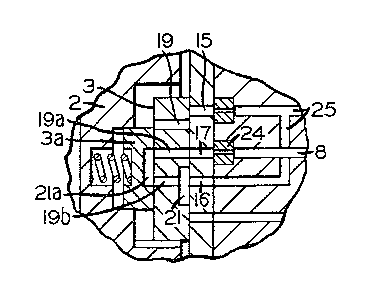
Referring to FIG. 1 of the drawings, there is shown
incorporated in the emergency portion 1 of a conventional
freight brake control valve device, such as the A~D freight
brake control valve manufactured by Westinghouse Air Brake
Company, an emergency piston 2 having a main ~lide valve 3,
one planar face 4 of which engages the conforming seat 4a
in a slide valve bushing 5. A diaphragm 6 of piston 2
forms, with the valve body, a chamber 7 on one ~ide, to
which the compressed air carried in the trainline brake
pipe (not shown) is connected via a brake pipe branch
passage 8, and a chamber 9 on the oppo~ite side subject to
the compre3sed air in a quick-action chamber (not shown).
The quick-action chamber pressure is charged from brake
pipe branch passage ô via a choke 10, chamber 9, and a
13~ B
passage 8a, 80 that, during brake pipe charging, the
pressure in chamber 7 is greater than the pressure in
chamber 9, and the effective force due to this pros~ure
differential acting acros~ the area of the piston
establishes and maintains the piston in its lower-~ost
release position (as shown) until ~uch time a~ the brake
pipe pres~ure is reduced. Thi3 release position is
determined by engagement of the emergency pl~ton tail 11
with a spring-loaded spool valve 12 th~t provides the
well-known emergency accelerated release function, which is
not a part of the present invention.
The emergency piston nain slide valve 3 is housed
within a recess 13 in the emergency piston, the axial
dimenæion of recess 13 being greater than that of main
slide valve 3, 80 that the main slide valve is moved
axially by pi~ton 2 with lost motion therebetween. A
greaduating slide valve 3a is carried fast in a further
recess 13a of piston 2 80 that a planar face 3b of the
graduating valve engage~ a conforming face 3c of main slide
valve 3. The respective faces of the main slide valve,
slide valve seat and graduating ~lide valve are lapped to
provide an effective metal-to-metal seal ther0between.
A ~pring 14 in recess 13a between the body of piston 2 and
graduating slide valve 3a urge~ the adjoining ~aces of the
main slide valver slide valve seat and graduating valve
together with sufficient force that the lapped interfaces
1 3(~
therebetween provide a pressure seal between the
passageways therein.
There are four such passageways 15, 16, 17, and 18 in
the bushing 5, three pa~ ageways 19, l9a and l9b in ~ain
slide valve 3, in addition to a groove 21 that is formed in
the face 4 of slide valve 3, and a groove 21a that i8
formed in the face 3b of graduating slide valve 3a. A
passage 22 in piston 2 connects quick-action chamber air in
chamber 9 to recess 13, 13a, wherefrom this guick-action
chamber air i connected to the main slide valve/~eat
interface via passageway 19 and also via a fluted
passageway 22a formed along the one side of recess 13
adjacent the side of main slide valve 3. Passageway 15
contains a quick-action chamber breather choke 23, and
passageway 17 contains an accelerated application choke 24,
the latter being smaller in size than the former for a
purpose hereinafter discussed. Passageways 15 and 16 are
interconnected in the valve body with a passageway 25 that
is vented to atmosphere. Passaqeway 17 is connected to
passage 8, while passageway 18 is connected to au~iliary
valve devices (not ~hown) which initiate ~nd propagata the
emergency application of the ~rain brakes.
In the relea3e position sho~n in FIG. 1, the opening of
passagew~y 19 at the slide valve~seat interface lies
intermediate passageways 15 and 17, so that the ~lide valve
interrupts fluid pressure comMunication between the~e
13~ ;2V~
pas~agew~ys. Similarly, groove 21 in main slide valve 3
cover~ the opening of passageway 16 in bushing 5, ~o that
the main slide valve/seat interfac,~ interrupts ~luid
pressure communication between passageway 16 and each
of passageway 17 and 18 adjacent thereto. Also, the
opening of passageway 18 is covered by face 4 of slide
valve 3 to isolate passageway 18 from fluid presRura
communication with recess 13, 13a. Also, ~lide valve
passage 19 is open at face 3c to recess 13, while
passageway l9a is blanked by graduating valve 3a at the
graduating slide valve/main slide valve interface, and
passageway l9b is blanked by the graduating valve groove
21a.
During a selective service rate of reduction of the
pressure carried in the trainline brake pipe, as is well
known, the service portion (not shown) of the A~D control
valve device effects a service brake application, while
concurrently, the brake pipe pressure reduction i8
registered in chamber 7 via passage 8. Due to the fact
that choke 10 prevents the guick-action chamber pressure
effective in chamber 9 from reducing at the same rate as
the pressure reduction effective at chamber 7, a pres~ure
differential is establi~hed across piston 2 to force the
emergency piston in an upward direction from release
position toward emergency application position.
A well known function of the emergency piston during
service brake applications is to establish a venting or
~3C~
"breathing" of quick-action chamber pres3ure in respon~e to
move~ent of emergency piston 2 toward emergency application
position. Accordingly, the pres~ure effective in ahamber 9
iB reduced at a rate sufflcient to counteract a service
rate of brake pipe reduction effective in chamber 7,
thereby stabilizing the emergency piston against further
movement to emergency ~pplication position. In accordance
with the present invention~ a further function of the
emergency piston is to provide an accelerated application
of the brakes in response to thi3 controlled movement of
the emergency piston during a service brake application.
Initial upward movement of pi~ton 2 from the release
position shown in FIG. 1 to the preliminary service
position shown in FIG. 2, in response to a selective
service rate of reduction of brake pipe pressure, occurs
without piston 2 effecting movement of main slide valve 3,
due to the initial space between piston recess 13 and the
~ain slide valve. This lost motion between eiston 2 and
main slide valve 3 allows the graduat~ng valve 3a to be
shifted upwardly by piston 2 relative to main slide valve
3, whereby groove 21a establishes a first fluid pressure
flow path in which slide valve pa~sageways l9a and l9b are
communicated. Accordingly, brake pipe pressure in
passageway 8 is vented via choke 24, seat passage 17,
passage l9a, groove 21a, passage 19b, groove 21, passage
16, and eassage 25. Thi~ initiates a local reduction of
brake pipe pressure to supplement the trainline brake pipe
c~
pressure reduction prior to the quick-actiom chamber
"breathing" function occurring, since passageway 19 re~ains
cut off from passageway 15 leading to vent passage 25 until
such time a9 slide valve 3 is shifted from its po~ition
shown in FIGS. 1 and 2. The purpo~e in initiating a local
reduction of brake pipe pressure prior to occurrence of the
aforementioned quick-action chamber "breathing" function is
to effect positive movement of the emergency piston
upwardly toward emergency application position in response
to even light reductions of brake pipe pressure, thereby
assuring that an accelerated application of the brakes is
achisved.
As this local reduction of brake pipe pressure occurs,
the differential pressure between chambers 7 and 9 acting
across piston 2 thus tends to increase, encouraging
continued upward movement of piston 2 from the preliminary
service position shown in FIG. 2 to an intarmediate service
position, a8 shown in FIG. 3. In this position, an
intermediate stage of ~ccelerated application exists in
whiGh pas~age 15 in bushing 5 is cracked open to passage
19, as main slide valve 3 i8 ~hifted upwardly by piston 2
together with graduating slide valve 3a, thereby in1tiating
the venting of guick-action chamber pressure effective in
chamber 9 via passage 22, recess 13, passageways 19 and 15,
choke 23, and pas~age 25. At this point, maximum venting
of brake pipe pressure i occurring via choke 24 and the
- ~3~
flow path established via main ~lide valve 3 and graduating
~lide valve 3a, while the venting of quick-action ~hamber
pressure is minimal dua to ths restricted flow
communication afforded by the craclced opening between
passageways 19 ~nd 15. Consequently, an upward-acting
pre~sure differential continues to develop across pi~ton 2,
to thereby as3ure continued upward movement of the piston.
As shown in FIG. 4, movement of main slide valve 3 and
graduating slide valve 3a with piston 2 provides a second
fluid flow path between seat passages 16 and 17 via slide
valve groove 21 in bypa~s of groc,ve 21a, for a purpose
hereinafter explained, while concurrently, passages 15 and
19 are brought into full communication, this latter
communication constituting a third fluid flow path. In
this maximum accelerated Application position, full flow
communication i~ establi~hed via the respective porting of
the connected passageway~ of the third flow path. Choke 24
in passage 8 is thus amployed to e3tablish the maximum
amount of brake pipe fluid under pre7~sure that is vented
locally to supplement the trainline redu,ction of brake
pipe pressure, while choke 23 in pa~sage 25 establishes the
venting or "breathing" of qulck-action chamber pressure at
a maximum level. Choke 23 is 3elected such that this
maximum "breathing" of quick-action chamber pressure causes
the pressure in chamber 9 to blowdown faster than the
pressure effective in chamber 7, thereby reversing the
pre3sure differential between chambers 7 and 9.
Accordlnqly, continued upward ~ove~ent of piston 2 18
halted before reachlng the e~ergency applioation pos~tion
shown in FIG. 6, to provide service ~tability. Moreover,
the reversal of the pres3ure differential between chaobers
7 and 9 initia~es a downw~rd ~ove~ent of piston 2, which
initially occurs without effecting novement of sllde valve
3, due to the space between the ~ain slide valve and piston
2 at the upper slde of recess 13. Since graduating valve
3a is ~a~t with piston recess 13a, the graduating valve
is shlfted downwardly relative to the slide valve ~uch that
groove 21a interrupts com~unication between ~lide valve
ports l9a and l9b, as shown in FIG. 5. Thls s~tabliRhes a
prelimlnary cut-off of the local brake pipe venting,
thereby leaving slide valve groove 21 as the lone flow
path connectlon via which continued local exhaust of brake
plpe pressure is controlled. Upon enyagem~nt of piston 2
with slide valve 3, a~ shown in FIG. 5, further downward
deflection of piston 2 will result in the flow area of the
connection between groove 21 and ~eat passage 17 being
reduced, ~o that the local exhAust of brake pipe pre~sure
is accordingly reduced. Concurrently, the flow area of the
connectlon between pa~sage~ 19 and 15 at the ~lide
valve/seat interface 18 also rsduced untll the plston finds
a steady state poRltlon in it~ downward travel between
prelininary cut-off position (FIG. 5) and release position
13
3 3~:~0;~0~
(FIG. l) in which the effective pressure in chaob~r 7
resulting from the continuing local venting of brake pipe
pressure is counterbalanced by the effective reduction of
guick-action chamber pressure effective in chamber 9.
This establi hes the amount of continuing exhau t of brake
pipe prssure locally, that is, supplementary to the
selective reduction of trainline brake pipe pre~sure, for a
given rate of reduction of brake pipe pressure during
servlce braking, thereby providing an accelerated
application of brakes. This action will continue as long
a~ the ~elective trainline reduction of brake pipe pressure
continue~.
The rate of reduction of brake pipe pressure that can
normally occur during a ~ervice brake application varies
over a fairly wide r~nge, depending upon, for example,
the train length, the position of a given car in the
train, and the amount of brake pipe leakage that exists.
This range of service rates is accounted for by the
emergency piston assuming different "steady ~tate"
positions in which the consequent size of the port opening
between passages 15 and l9 ~t the ~lide valve/seat
interface change3 to establish a rate of quick-action
chamber pressure "breathing" which matches or balances the
existing brake pipe pre~sure reduction.
The size of choke 24 via which the local exhaust of
brake pipe pressure occurs is selected 80 that, ~hen the
trainline brake pipe pressure reduction i~ terminated, the
1~
~3~
1OCA1 exhaust of brake pipe pre~sure effective in chamber 7
i8 insufficient to balance the contlnuing rsdu tion of
quick-action chamber pressure effective in chamber 9. The
consequent preY~ure differential across piston 2 will force
the piston downwardly from its steady state po~ition toward
release position. It ~ill be appreciated now that, during
this further downward deflection of piston 2, the slide
valve groove 21 connecting passages 16 and 17 iB moved out
of communication therewith prior to the flow connection
between passagess 15 and 19 being cut off at the main ~lide
valve/seat interface. Since graduating valve groove 21a
had already interrupted flow communication via passages l9a
and l9b, as shown in the preliminary cut-off position of
FIG. 5, local brake pipe pressure is cut off from exhaust
prior to the exhaust of quick-action chamber pre~ure being
terminated. This final exhaust of guick-action chamber
pres~ure reinforces the downward acting pressure
differential across piston 2, thereby as~uring a positive
and complete movement of pi~ton 2 to release position, as
shown in FIG. 1, to terminate the accelerated application
function.
Returning now to FIG. 4, showing the emergency piston 2
in its maximum accelerated application position in which
maximum venting of brake pipe pressure and quick-action
chamber pres~ure is e~tablished, it will be understood
that, in the event the trainlina brake pipe reduction
-
13~
exceeds a service rate, the "breathing" or venting of
quick-action chamber pressure via choke 23 will be
insufficient to rever~e the upward acting pre~sure
differenti~l across piaton 2. Thus, in~tead of piston 2
moving back toward a steady state position,~s ~hown in FIG~
5, as previously discussed with respect to a service brake
application, the effective pressure differential will
maintain continued upward movement of the pi~ton to
emergency position, as shown in FIG. 6. In this po~ition,
passage 19 is cut off from passage 15 at the main ~lide
valve/seat interface to terminate the quick-action chamber
breathing function, while concurrently the lower end of
slide valve 3 uncovers pas3age lô to connect quick-action
chamber pressure from reCejJ 13, 13a to a vent valve device
(not shown)~ for piloting an emergency brake application in
~ well-known manner.
In accordance with the foregoing, it will be understood
that the accelerated brake application function is
accomplished more reliably than heretofore, by reason
of the fact that positive emergency piston operation is
encouraged in both the application and release directions.
the main slide valve/graduating valve arrangement with lost
motion therebetween makes it possible to achieve llnear
control functions in a different sequence than normal.
Normally, the fir~t control function to operate during
movement in one direction is the la~t control function
16
~3~ 3
to operate during movement in the opposite direction
and vice verYa. In accordance with the present invention,
this control seguence i8 reversed. That is, brake plpe
preY8Ure i8 exhausted prior to exhauYting quick-action
chamber pressure during piston movement toward application
position, but during piston movement in the opposite
direction toward release position, the exhaust of brake
pipe pressure is terminated prior to the exhaust of
~uick-action chamber pressure being t~rminated. Thus, tha
initial exhaust of brake pipe pressure prior to the exhaust
of quick-action chamber pressure tend~ to increase the
pressure differential across piston 2 in the direction of
movement toward application pofiition thereby achieving
positive piston operation without the liklihood of piston
stalling to achieve the accelerated application function.
~oreover, during piston movement toward releaYe position,
the exhaust of brake pipe pre~sure is terminated prior to
terminating the exhaust of quick-action chamber pressure,
thereby tending to increase the pressure differential
across piston 2 in the direction o~ movement thereof, i.e.,
toward release position. Again, this has the effect of
~chieving more positive piYton movement to assure
termination of the local br~ke pipe reduction and thereby
prevents any poYsibiity of the local brake pipe reduction
sustaining the brake application following termination of
the selective trainline brake pipe pressure reduction.