Note: Descriptions are shown in the official language in which they were submitted.
~3~C~ S
FIELD OF TEIE_ INVENTION
The inVentiQn generally relates to electronically
commutated reluctance motors and more particularly to
electronically commutated reluctance motors operated
as continuously rotating variab:Le-speed drives.
E~ACKGROUND OF TEIE INVENTION
- !
The basic characteristics of electronically
commutated reluctance motors operated as continuously
rotating variable-speed drives are well known, since
they are members of the class of variable reluctance
motors, commonly used in stepper motor applications.
As variable-speed drives, electronically commutated
reluctance motors are designed for efficient power
conversion rather than for particular torque or
control characteristics typically required in stepper
motor applications, and the pole geometry and control
strategies differ accordingly. For example, the
number of rotor teeth is relatively small in an
electronically commutated reluctance motor (cf.,
variable reluctance stepper motors), giving a large
step angle, and the conduction angle i5, generally,
modulated as a function of both speed and torque to
optimize operation as a variable-speed drive. As a
term o~ art, these variable-speed reluctance motors
are generally known as switched reluctance.
Because of recent developments in power semi-
conductor devices such as power MOSFETs and insulated
gate thyristors (IGTs). Switched reluctance motors
have gained attention relative to other types of
motors suitable for variable-speed drive
applications. This increased attention derives from
the fact that switched reluctance motors compare very
favorably with ot~er types of motors typically used as
~'
--1--
39-149/mld
~L3~C~2~S
variable-speed drives. For example, the speed versus
average torque curves for switched reluctance motors
are very similar to the curves for brushless permanent
magnet (PM) motors -- e.g., the curves are fairly
linear with no discontinuities of torque.
Additionally, switched reluctance motors are the
cheapest type of motor to manufacture. They are
rugged and robust and therefore well suited for heavy
duty use. They have excellent heat dissipation
qualities, and they do not require brushes or slip
rings. The drive circuits for switched reluctance
motors are the simplest and lowest cost compared to
drives for other motors. Moreover, using state-of-
the-art semiconductor technology for controllers, the
efficiency of switched reluctance motors compare very
favorably with other classes of variable-speed motors
such as inverter-driven ~C motor and PM motors.
Although the foregoing comparative features are
favorable, switched reluctance motors are also known
to have several disadvantages which are common to all
variable-speed drive motors. Specifically, copper,
hysteresis and eddy current losses limit motor
efficiency, especially at relatively high RPMs.
SUMMARY OF T~E INVENTION
It is a general object of the invention to
provide a switched reluctance motor construction
having improved performance characteristics. In this
connection, it is a specific object of the invention
to provide a construction for a switched reluctance
motor which has a greater efficiency than switched
reluctance motors of conventional construction,
particularly at higher RPMs.
39-149/mld
~3~z~
A related object of the invention is to provide a
switched reluctance motor of improved efficiency
without sacrificing the highly desirable features of
conventional switched reluctance motors such as lowest
manufacturing costs oE any motor type, operation over
a wide range of RPMs and very low losses from the end
turns of stator windings.
It is a more particular object of the invention
to substantially reduce losses in the back iron region
of the stator of a switched reluctance motor. In this
connection, it is a detailed object of the invention
to significantly reduce hysteresis and eddy current
losses in a switched reluctance motor.
It is yet another particular object of the
invention to significantly improve the electrical
response characteristics of switched reluctance motors
in order to allow for operation of switched reluctance
motors at very high speeds -- e.g., greater than
10,000 RPM.
Other objects and advantages of the invention
will be apparent from the following detailed
description and the accompanying drawings.
Briefly, according to the invention, reversals oE
the flow of flux in a motor are eliminated so that
hysteresis losses are significantly reduced relative
to conventional switched reluctance motors. Moreover,
the motor of the invention is constructed in a manner
which allows for each area of the back iron of the
stator to be incorporated into only one of the
magnetic circuits formed by the motor and its drive.
Such a construction greatly reduces the eddy current
losses relative to conventional switched reluctance
motors since the frequency of collapsing and building
of magnetic ~ields in the back iron area of the stator
39-149/mld
~3t~(~Z~5
is greatly reduced. By greatly reduclng hysteresis
and eddy current losses, the invention provides an
electronically commutated motor that is characteri~ed
by significantly higher efficiency than prior art
switched reluctance motors, while retaining all of the
ad-antages of these prior art motors.~-
Electronically commutated reluctance motorsaccording to the invention are hereinafter referred to
as ECR motors. These ECR motors are characterized by
first and second members mounted for relative rotation
wherein one of the members has evenly spaced teeth and
the other member has unevenly spaced teeth such that
when the teeth of each member are polarlzed they
deEine pairs of adjacent poles having opposite
polarities. In the illustrated embodiments of EC~
motors, the rotor has evenly spaced teeth and the
stator has unevenly spaced teeth. Althoug~ not an
illustrated embodiment, the concepts of the invention
may also be applied to an ECR motor having evenly
spaced teeth on the stator and unevenly spaced teeth
on the rotor.
In all embodiments of the inventionj windings are
wrapped about the teeth of the stator in a manner
which allows the teeth of the stator to ~e energized
as pairs of adjacent poles having opposite polarities
so as to create a magnetic circuit between each o~ the
pole pairs. Both poles of a pair are always excited
together in any energization scheme utilized to drive
the ECR motor, thereby ensuring the primary magnetic
circuit formed by the pair is through the back iron
area of the stator bridging the two teeth. By
ensuring the primary magnetic circuit formed by either
pole in a pair is between the poles of the pair, flux
reversals in the stator may be eliminated. Further-
more, by energizing the motor so that no magnetic
39-149/mld
~31~Z~L~
circuits are generated which link stator pole pairs,
each area of the back iron of the stator experiences a
flux flow for only one phase. Thus, the switching
frequency of the flu~ in the back iron of the stator
is equal to the switching frequency of each phase. In
contrast, the switching frequency of the flux in the
back iron of conventional switched reluctance motors
is typically three times the switching frequency of !
each phase. The switching frequency of the flux in
the back iron of the stator is related to the eddy
current losses of the motor. By reducing the
switching frequency oE the flux, eddy current losses
are also reduced.
By providing the uneven spacing of teeth on
either the stator or rotor, the energization schemes
according to the invention provide torque to the rotor
and allow positive control of the direction of rotor
rotation. In order to provide a low reluctance path
between stator and rotor, the poles of each pair of
unevenly spaced teeth are separated by a distance or
angle equal to that of the evenly spaced teeth of the
stator or rotor. Such a relationship allows each pair
of unevenly spaced teeth to be aligned with an
adjacent pair of evenly spaced teeth so as to provide
a low reluctance path for the flux flowing between the
poles in the pairs. To ensure torque is generated at
the rotor, the neighboring teeth of adjacent pairs of
unevenly spaced teeth are separated by a distance that
is not equal to the spacing between the evenly spaced
teeth or an integer multiple thereof.
Various energization schemes may be employed to
power an ECR motor according to the invention. Using
a polyphase source, the ECR motor may be driven so
that only one phase is on at any given time, two
phases on at any given time, etc., depending on the
_5_
39-149/mld
~3~21~
number of phàses in the source. Alsol the ECR motor
may ~e energized by a hybrid scheme wherein the motor
is at different times driven by a different number of
phases. Such a scheme ma-y be realized by merely
partly overlapping the on times of each phase.
Each phase energizes one or more pairs of
adjacent stator teeth so that each pair comprises
opposite poles which draw adjacent pairs of rotor
teeth into alignment, thus providing a low reluctance
path for flux flowing between the pole tips of the
polarized pair. When more than one pair of adjacent
stator teeth are energized at a time, the relative
positions of-the polarities of the poles in the pairs
are preferably controlled so as to prevent the
creation of secondary magnetic circuits linking two
pairs of stator teeth by way of a flux path that
crosses the primary magnetic circuit of unenergized
pairs of stator teeth. These secondary magnetic
circuits effectively increase the flux switching
frequency for those portions of the stator back iron
where the primary and secondary circuits overlap. To
prevent the occurrence of such secondary magnetic
circuits linking pairs of stator teeth, the relative
polarities of simultaneously polarized pairs are
preferably maintained such that neighboring poles
separated by unenergized pairs of poles are of the
same-polarity.
Depending upon the particular configuration of
the ECR motor and the selected drive-scheme, either a
unipolar or bipolar drive may provide the foregoing
polarization relationship between stator pairs. In
order to maintain a unipolar drive, an ECR motor of
the invention may be driven such that some secondary
magnetic circuits are generated. Although these
secondary magnetic circuits generate a flux flow which
39-149/mld
~L3~Z~i
overlaps other magnetic circuits and thereby increases
the eddy current losses from a minimum value, the
directions of the flows in the overlapping area are
the same. Accordingly, no flux reversals are
generated and hysteresls losses are not substantially
increased. For some applications, a slight decrease
in efficiency caused by an increase in eddy current
losses may be an acceptable trade-off to achieve the
use of a less expensive, unipolar drive.
BRIEF DESCRIPTION OF TE~E DRAWINGS
FIGURE 1 is a schematic cross-sectional view of a
conventional switched reluctance motor construction,
illustrated in a six stator pole and four rotor pole
configuration;
FIG. 2 is an exemplary and ideali~ed graph
illustrating a cyclic variation of inductance L exper-
ienced by a given phase relative to a mechanical angle
of the rotor;
FIG. 3 is an exemplary graph of a current wave-
form for a given phase relative to the time t of
mechanical rotation of the rotor, illustrating how the
commutation of a phase must lead the mechanical
rotation of the rotor in order to ensure continuous
motoring;
FIG. 4a is a schematic cross-sectional view o~ a
three-phase electronically commutated reluctance (ECR)
motor incorporating the invention, with the windings
of the stator poles wound in accordance with a first
embodiment and with the rotor aligned with an
energized phase A in keeping with a one-phase~on
operation;
FIG. 4b i5 the same schemaeic cross-sectional
view of a three-phase ECR motor shown in FIG. 4a,
39-149/mld
~L3(~15
. .
except the rotor has been rotated to align with an
energized phase B;
FIG. 4c is the same schematic cross-sectional
view of a three-phase ECR motor shown in FIGS. 4a and
4b, except the rotor has been further rotated to align
the rotor with an energized phase C;
FIG. 5a is a schematic cross-sectional view of!a
three-phase ECR motor according to the invention where
the windings of the stator poles are wound in
accordance with a second embodiment and with the rotor
aligned with an energized phase A in keeping with a
one-phase-on operation;
FIG. 5b is the same schematic cross-sectional
view of a three-phase ECR motor illustrated in FIG.
5a, except the rotor has been rotated to align with an
energized phase B;
FIG. 5c is the same schematic cross-sectional
view of a three-phase ECR motor illustrated in FIGS.
5a and 5b, except the rotor has been rotated to align
with an energized phase C;
FIG. 6a is the same schematic cross-sectional
view of a three-phase ECR motor incorporating the
second embodiment of the invention as shown in FIGS.
5a-c, except the rotor is aligned with simultaneously
energized phases A and B in a two-phase-on operation;
FIG. 6b is the same schematic cross-sectional
view of a three-phase ECR motor shown in FIG. 6a,
except the rotor is rotated to align with
simultaneously energized phases B and C;
FIG. 6c is the same schematic cross-sectional
view of a three-phase ECR motor shown in FIGS. 6a and
6b, except the rotor is rotated to align with
simultaneously energiæed phases C and A;
39-149/mld
~3~Z15
' ~.
FIG. 7a is the same ECR motor illustrated in
FIG. 6c, except the illustrated flux'paths have been
modified to indicate the magnetic circuits formed if
the motor is not energized with a waveform as set
forth in FIG. 7c; :
FIG. 7b is a schematic block diagram oE an
exemplary three-phase drive apparatus;for exciting an
ECR motor according to the invention, wherein more
than one phase is excited at any time; '~'
FI~. 7c is a schematic diagram of the current
waveforms produced by the three phases of the drive
apparatus of FIG. 7b; ' ` ~
FIG. 8a is a schematic cross-sectional view of a
three-phase ECR motor according to a third embodiment
of the invention where two pairs of stator poles àre
energized per phase and the rotor is aligned with
stator poles of phase A in a one-phase-on operation;
FIG. 8b is the same cross-sectional~view of the
ECR motor as shown in FIG. 8a, except the rotor is
rotated to align'with the stator poles of phase B;
FIG. Bc is the same cross-sectional view'of the
ECR motor as shown in FIGS. 8a and 8b, except the
rotor is rotated to align with the stator poles of
phase C;
FIG. 8d is the same cross-sectional view and
energization of the ECR motor as shown'in-FIG. 8c,
except the polarities of the stator poles have been
rearranged to illustrate how an incorrect arrangement
of polarities generates unwanted magnetic circuits;
FIGS. 9a-9c are schematic diagrams of the ECR
motor illustrated in FIGS. 8a-d, illustrating the
polarities of the stator pole ~eeth for a two-phase-on
operation; "
39-149/mld
:,
z~s
FIG. lOa is a schematic and idealized diagram of
the current waveforms an energization scheme of a
three-phase ECR motor according to the invention,
where the energization scheme ls a hybrid of one-
phase-on and two-phase-on schemes;
FIG. lOb is the same cross-sectional view o~ the
ECR motor shown in FIGS. 8a-8d, except the motor i5
shown as energized by a hybrid drive scheme during the
time both phases A and B are on as indicated by FIG.
lOa;
FIG. lOc is the same cross-sectional view of the
ECR motor shown in FIGS. 8a-~d, except the motor is
shown as energized by a hybrid drive scheme during the
time both phases B and C are on as indicated by FIG.
lOb;
FIG. lOd is the same cross-sectional view of the
ECR motor shown in FIGS. 8a-8d, except the motor is
shown as energized by a hybrid drive scheme during the
time both phases C and A are on as indicated by FIG.
lOa;
FIG. lOe is the same cross-sectional view oE the
ECR motor shown in FIG. lOd, except a unipolar drive
energizes the coils oE phases C and A, thereby
generating an extra but not harmful ~no flux reversal)
magnetic circuit once every cycle of the phase
sequence;
FIG. 11 is a perspective view of an assembly for
a three-phase ECR motor incorporating the invention in
accordance with a preferred embodiment, with part of
the stator laminations cut away to expose the rotor;
FIG. 12 is a cross-sectional view of the ECR
motor assembly of FIG. 11 taken along the line 12-12
in FIG. 11;
--10--
39-149/mld
~3~ Z~5
FIG. 13a is a cross-sectional view of an
exemplary "inverted" ECR motor taken along the length
of the motor, incorporatinq the invention according to
a fourth embodiment;
FIG~ 13b is a cross-sectional view of the
"inverted" motor of FICo 13a, taken along the line
13b~13b and effectively showing the configurations~of
a stator and rotor laminationc: according to the
invention; and
FIG. 14 is an illustration of an exemplary linear
ECR motor incorporating the invention according to a
fifth embodiment.
While the invention will be described in
connection with several alternative embodiments, there
is no intent to limit the invention to those embodi-
ments. On the contrary, the intent is to cover all
alternatives, modifications and equivalents included
within the spirit and scope of the invention as
defined by the appenæed claims.
D~:TAILED DE~CRIPTION OF T~E ILLUST~ATIVE EMBODIMENTS
Turning to the drawings and referring first to
FIGURE 1, a typical three-phase, prior art switched
reluctance motor 15 is characterized by a rotor 17
without windings, permanent magnets or a commutator.
Because the rotor 17 is without windings or permanent
magnets, the rotor has a low inertia compared to AC or
PM motors. A stator 19 is characterized by a rela-
tively small number of copper phase windings (only one
pair of series connected windings Al and A2 is shown)
and with very short end windings 23 -- a significant
advantage over AC or PM motors which increases the
efficiency of switched reluctance motors.
39-149/mld
~L31~21S
The rotor 17 which rotates about a steel shaft 25
is simply a stack of laminations comprising a mag-
netically permeable steel alloy. As suggested by
FIGURE 1, each rotor lamination is cut to form a
number of salient poles which extend radially
outwardly from the axis of rotor rotation and are
circumferentially evenly spaced about the periphery of
the rotor 17.
As with the rotor 17, the stator 19 is preferably
formed by a stack of laminations made from a mag-
netically permeable steel alloy. In order to cause
rotation oE the rotor 17 as explained hereafter, the
stator includes a number of salient poles 27 which is
unequal to the number of salient poles 31 on the rotor
17. The stator poles 27 extend radially inwardly from
an annular yoke 29 and are circumferentially and
evenly spaced about the yoke.
The switched reluctance motor of FIGURE 1 has six
stator poles 27 and four rotor poles 31. Windings on
diametrically opposite stator poles 27 are connected
in series to form phases -- three in this case (A, ~
and C). For ease of illustration, winding pairs B and
C are not shown in FIGURE 1; instead, the stator poles
associated with these windings are labeled "B'l or "C"
accordingly. As those familiar with switched
reluctance motors will appreciate, different combi-
nations of the numbers of stator and rotor poles may
be used -- for example, an eight stator pole and six
rotor pole combination will give a four-phase machine
with a nominal 15 angle oE rotor rotation for each
commutated phase. The six stator pole and four rotor
pole motor shown in FIGURE 1 has a step angle of
30. For identification of particular stator poles
27, reference hereinafter will be made to the stator
pole and its winding -- e.g., in FIGURE 1 the stator
-12-
39-1~9/mld
~3~
poles of phase A are 27 (Al~ and 27 lA23, where Al and
A~ comprise the winding pair for phase A.
The excitation of windings Al and A2 of phase A
magnetizes both the stator 19 and the rotor 17. As
illustrated, this excitation produces a torque causing
the rotor 17 to align its poles 31 with the excited
stator poles 27 (Al) and 27 (A2). The polarity of the
torque does not depend on the polarity of the current
since the rotor 17 is always attracted to the stator
19 and will rotate to an orientation which provides a
minimum reluctance path between energized poles.
Conse~uently, the switched reluctance motor requires
only unipolar current through the phase windings and
from a drive generally indicated as 33 in FIGURE 1.
Sequential excitation of the phase windings A, B and C
provides a "one-phase-on" operation which causes the
rotor 17 to rotate and synchronously align the poles
31 of the rotor with those excited on the stator 19.
In a conventional manner, a shaft position sensor 35
provides to the driYe 33 the rotor position infor-
mation necessary ~or synchronization of the rotor
rotation and phase excitation.
Torque in the switched reluctance motor is
proportional to the rate of increase of flux carried
by the rotor and stator poles 31 and 27, respectively,
as they rotate into alignment. Both air-gap
reluctance and pole reluctance simultaneously decrease
as the rotor 17 rotates into a position that is
radially aligned with the energized stator poles 27
(Al)-and ~7 (A2). It is known that magnetic
saturation in the air gap region and pole tips of the
switched reluctance motor can significantly enhance
the torque output. In this regard~ the desire for
pole tip saturation to increase output torque dictates
a radially length of an air gap 37 as small as
po~sible for reasonable manufacturing ease.
-13-
39-149/mld
~3i.P~'ZlS
Referring to the drive 33 for the switched
reluctance motor shown in FIGURE 1, only the basic
electrical circuit used to drive the phase A windings
~1 and A2 of the switched reluctance motor is
illustrated. It will be appreciated that the drive 33
includes similar electrical circuitry for phases B and
C. For phase A, when the gates 39 and 41 of the drive
33 are closed, current builds up in the windings A
and A2 under the excitation of direct voltage from a
power source 43. When the gates 39 and 41 are open,
the current transfers to the diodes 45 and 47, and the
windings Al and A2 see the reverse voltage which
causes the current to collapse. Pulses of current are
thereby supplied to each of the phases A, B and C in
sequence and, for motoring operation, each pulse
causes the most adjacent rotor pole to move towards
alignment with the energized stator pole.
As indicated by the arrow 49, th~ rotor 17 steps
around in the opposite direction to the sequence of
stator pole excitations as is well known in the art.
It should be noted, however, that thinking ~n terms oE
"steps" of rotor rotation is only helpful from the
viewpoint of understanding the rotation -- in practice
the current pulses are controlled by the controller 51
in response to the rotor position sensor 35 to occur
at specific angles ~ of the rotor. The commutation of
the current is controlled to occur at speciEic rotor
angles ~ in order to give a smooth rotational
transition of a rotor pole 31 passed an attracting
stator pole 27 in order to ensure continuous rotation
without cogging. This generally means that a phase
winding is substantially de-energized before the
stator and rotor poles 27 and 31 align.
Briefly turning to a more detailed discussion of
motor operation, motoring torque in an switched
-14-
39-149/mld
~L3~2~
reluctance motor is produced if a phase is energized
during the time interval when the inductance of the
phase is increasing (i.e., a rotor pole is approaching
a stator pole of the phase). A given phase undergoes
a cyclic variation of inductance as rotation occurs.
Making the simplistic assumption that the inductance L
is independent of the current, this variation is shown
in FIG. 2 for each stator pole in a phase. ~ first
rotor pole aligns with the stator pole at a rotor
angle of ~1 With continued rotor rotation, the next
alignment of a rotor pole occurs at ~2. As can be
seen, the inductance L is the greatest when a rotor
pole is aligned with the stator pole. In the four-
pole rotor of FIGURE 1, the difference ~2 ~ ~1 equals
45, since the rotor poles are evenly spaced. The
mechanical angle of rotor rotation between low
inductance points is hereinafter referred to as the
"stroke an~le."
For continuous rotation of the switched
reluctance motor, the timing of a typical energizing
current pulse applied to a winding relative to the
time of rotor angle ~1 is shown in FIG. 3. Energy is
controllably supplied during the period up to the com-
mutation time Tl, by the openinq and closing of gates
39 and 41 -- i.e., pulse-width modulation. ~o ensure
motoring operation with no more than acceptable ripple
torque, the commutation time Tl occurs at a time
before the mechanical angle ~1 is reached; that is,
the phase winding is cornmutated before stator and
rotor poles 27 and 31 align. Also, by commutating
during a time of rising inductance L, a maximum amount
of energy may be converted to motoring and a minimum
to generating. In other words, during excitation of a
phase by a current I, some of the energy is converted
to mechanical output, some is stored in the magnetic
-15-
39-149/mld
~3~
field and some is lost in the copper or iron. During
the period after commutation, the continued rotation
of the rotor 17 partly returns the energy to the
supply and partly converts it to further mechanical
output and losses.
The primary source of losses in an switched
reluctance motor occurs in the stator 19. The losses
in the stator 19 primarily consist of hysteresis and
eddy current losses. To reduce the eddy current
losses, the stator 19 and rotor 17 are constructed of
a laminated steel alloy as previously indicated. Eddy
current losses, however, remain significant and are
related to the frequency of the cyclic building and
collapsing of magnetic fields in the stator. In con-
ventional switched reluctance motors such as the motor
of FIGURE 1, all portions oE the back iron experience
a cycle of building and collapsing magnetic fields in
response to energization of the motor by each phase.
The frequency of this cyclic building and collapsing
of magnetic fields in the stator is hereinafter called
the "flux switching frequency." In the conventional
motor of FIGURE 1, the flux switching frequency in the
back iron of the stator is equal to three times the
phase switching frequency or commutation frequency.
As for the hysteresis losses, the frequency of
flux reversal effects their magnitudes. Flux
reversals are created when the direction of flux flow
in overlapping magnetic circuits conflict. Such a
conflict can occur using various drive schemes.
Typically, the stator poles do not experience flux
reversals. However, segments of the back iron or yoke
29 of the stator 19 may experience a flux reversal for
each switching of the phases, the rotor poles 31 may
experience as many as one flux reversal per
revolution.
-16-
39-149/mld
r;
~ ecause of non-linearities introduced by
operation of the switched reluctance motor in
saturated conditions, the procedure for calculating
losses in a switched reluctance motor is complex.
However, an easy and quantitative comparison can be
made between conventional switched reluctance motors
and motors according to the invention since it is
known that the flux switching frequency and the
frequency of flux reversals in the back iron of the
stator are related to eddy currents and hysteresis
losses in the motor, the two primary sources of iron
losses in motors.
With opposing stator poles,27 (Al) and 27 (A2)
associated with phase A as is shown in FIGURE 1, the
windings Al and A2 are oppositely wound about the
poles so that one pole face 27a has a north polarity
and the other has a south polarity. With this
configuration, the flux path is, as indicated by the
solid lines 51, through the rotor 17 and around the
back iron 29 of the stator 19. Upon energization of
stator poles 27 ~Bl) and 27 (B2) by phase B, the
associated windings (not shown) will set up a flux
pattern similar to that developed by windings Al and
A~ of phase A as indicated by a dashed lines 53. For
the segments 55 and 57 of the back iron or yoke 29, it
can be seen that the direction of the flow of the flux
reverses from phases A to B. Similar flux reversals
occur in other segments of the yoke 29 when phase B is
turned off and phase C is turned on. A third pair of
segments of the back iron or yoke 29 experiences flux
reversal when phase C is turned off and phase is
turned on. Collectively, the pairs of back iron
segments account for the entire area of the yoke 29.
The same type of flux reversal occurs during "two-
phase-on" operation of the three-phase switched
reluctance motor in FIGURE 1.
-17-
39-149/mld
` :l
L5
.
Because the flux paths for each phase extends
around the entire back iron area of the yoke 29, each
portion oE the back iron area i5 incorporated into
three flux paths -- one from each phase. Accordingly,
every portion of the back iron experiences a flux
switching frequency that is three times the switching
or commutation frequency of each phase. More
generally, conventional switched reluctance motors`
such as the motor of FIGURE 1 are characterized by a
flux switching frequency in the back iron of the
stator which is equal to the commutation frequency
multiplied by the number of phases energizing the
motor.
For a six stator, four rotor pole arrangement as -
~shown in FIGURE 1, one complete revolution of the
rotor requires four cycles of the phase sequence A, B,
C. In terms of motor RPM, each segment of the back
iron or yoke 29 experiences a flux change twelve times
per one complete rotor revolution and a phase reversal
four times. Operating at 7,500 RPM, the flux
switching frequency and frequency of flux reversal in
the stator of FIGURE 1 are 1500 HZ and 500 HZ,
respe~tively. As previously indicated, these
frequencies are indicative of core losses in the
stator primarily related to eddy current and
hysteresis losses, respectively.
In accordance with one important aspect of the
invention, a motor construction and energization
scheme are provided which minimizes the flux switching
frequencies and eliminates flux reversals in the back
iron or yoke of the stator of an electronically
commutated reluctance motor, hereinafter called an ECR
motor. ECR motors substantiàlly reduce eddy current
and hysteresis losses and increase motor efficiency,
especially at higher RPMs ~e.g., 2,000 RPMs and
-18-
39-149/mld
13~2~S
more). In this regard, the motor construction of the
invention is believed to provide high eEficiency
operation over a wide range of speeds, including
speeds as low as several hundred RPMs and in excess of
20,000 RPMs. In order to eliminate flux reversals in
at least the stator of the ECR motor, adjacent stator
pole teeth are polarized so as to have opposite
polarities. In addition to the elimination of flux!
reversals, energizing adjacent stator poles minimizes
the back iron of the stator in the magnetic path. By
minimizing the back iron in the magnetic flux path,
energy losses caused by the collapsing and building of
a magnetic field in the back iron are greatly
reduced. Specifically, the ECR motor is energized in
a manner to prevent or at least reduce (relative to
conventional switched reluctance motors) the over-
lapping of magnetic fields in the back iron of the
stator. By eliminating or reducing the occurrence of
overlapping magnetic fields in the back iron, the
frequency of collapsing and building magnetic fields
is drastically reduced. As a result of this
reduction, eddy current losses are substantially less
in an ECR motor than in a conventional switched
reluctance motor.
To ensure rotation of the rotor with a flow of
flux between adjacent pole pairs, the stator pole
teeth are unevenly spaced about the stator. Moreover,
the uneven spacing allows control of the direction of
rotor rotation. Specifically, the angle between
adjacent pole pairs forming non-overlapping magnetic
circuits (i.e., inter-pair angle) and the angle
between adjacent stator pole teeth in a pole pair
(i.e., intra-pair angle) are different. Stated
differently, the angle between~adjacent stator pole
teeth alternates between first and second angles.
--19--
39-149/mld
~3~Z~
For the purpose oE illustrating the principle of
the invention, FIGS. 4-6 are exemplary of ECR motors
according to the invention having one pair of adjacent
stator poles for each phase of a polyphase source.
The ECR motor of FIGS. 4-6 have three pairs of stator
poles for a three-phase source. In contrast to the
one pair of stator poles per phase construction
exemplified by FIGS. 4-6, FIGS. 8-lO illustrate an
exemplary embodiment of a motor construction according
to the invention having more than one pole pair per
phase. In the illustrated embodiment of FIGS. 8-lO,
two pole pairs per phase are shown; however, any
number of pole pairs per phase is possible, depending
on the desired performance characteristics. In this
regard, applicant regards the one pair per phase
design as ideally suited for very high speed appli-
cations because at high motor speeds the large torque
ripple inherent from the large stroke angles relative
to motors having two or more pole pairs per phase
becomes insignificant. Conversely, the low torque
ripple of motors having multiple pole pairs per phase
makes such motors better suited for lower speed appli-
cations.
Because the torque applied to the one-pair-per-
phase motor is unbalanced, applicant suspects the
wearing of bearings may be reduced by the more
balanced application of torque by a motor having two
or more pole pairs per phase. However, a one-pair-
per-phase motor may be ideally suited for low-cost and
high-speed applications. Requirements of particular
applications will determine which type of motor design
is chosen. For example, if incorporated in a servo-
motor, the construction according to the invention
would probably include mcre than two pole pairs per
phase in order to ensure minimum torque ripple.
-20-
39-149/mld
~3Cl C~Z~5
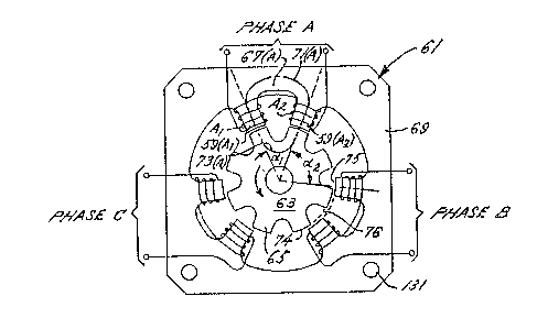
Referring first to the one pair per phase design
of FIGS. 4a-4c, the three pairs of adjacent stator
pole teeth 59 are circumEerentially arranged about a
stator 61. The two stator pole teeth 59 in a pair are
separated by an intra-pair angle of ~1 as measured
from the axis of rotation of the rotor 63. The
adjacent stator pole teeth 59 of neighbor;ng pairs are
separated by an inter-pair angle of ~2. In order ~o
provide for radial alignment of the rotor pole teeth
65 with the stator pole teeth 59 of a pair, the rotor
pole teeth 65 are spaced apart by the angle al.
With phase A excited, a torque is created which
draws the nearest pole teeth 65 of the rotor 63 into
alignment with the stator pole teeth 59 (Al) and 59
(A2) associated with series connected windings Al and
A2 as indicated by FIG. 4a. In order to ensure
continuous rotation (in contrast to step rotation),
commutation of phase A leads the mechanical alignment
of the rotor and stator pole teeth as discussed in
connection with FIGS. 1-3. In this regard, the radial
alignment of adjacent pairs of stator and rotor teeth
illustrated in FIGS. 4-5 is intended only to aid in
the understanding of the magnetic fields and not to
imply a step-like rotation of the rotor 63.
Magnetic energy flows between the adjacent stator
pole teeth 59 (Al) and 59 (A2) in the pole pair
associated with phase A via an area 67~A) of the back
iron or yoke 69 joining the two pole teeth. To
complete the magnetic circuit 71(A) for the flow of
magnetic energy or ~lux through the stator pole pair
59 (Al) and 59 (A2), the pole faces of the rotor pole
teeth 65 provide a bridge 73(A) that magnetically
~oins the pole faces of the stator pole pair. Also
part of the complete magnetic circuit 71(A) are the
areas of the radial air gap 75 interfacing the pole
-21-
39-149/mld
~3~Z~
faces of the rotor pole teeth 65 and the pole faces of
the stator pole pair 59 (Al) and 59 (A2).
Digressing briefly, it will be appreciated that
the particular dimensions of the pole faces 74 and 75
of the stator and rotor pole teeth 59 and 65~ respec-
tively, define the nature of the radial air gap 76.
For example, the pole faces may have arcuate shapes
referenced to the axis of rotor rotation. Such shapes
define a uniform air gap 76 illustrated in FIG. 4a.
Non-uniforrn air gaps result from all other shapes of
the pole faces. The particular shape chosen for the
pole faces is a design consideration unrelated to the
invention.
The stator and rotor teeth 59 and 65 are prefer-
ably tapered as illustrated in order to provide
structural resistance to deflection by the magnetic
coupling between rotor and stator teeth which may
cause vibration and to aid in the creation of flux
saturation at the pole faces. The taper is a radial
taper and extends from the base of the teeth to the
pole faces. Of course, the area of the pole faces of
the stator teeth 59 are related to the area of the
pole faces of the rotor teeth ~5 in order to achieve
desired operating characteristics as is conventional
in the art.
As can be seen in FIGS. 4a-4c, the taper is not
of equal slope on both sides of a stator tooth 59.
The slopes are adjusted in order to ensure sufficient
space is provided for the windings Al, A2, Bl, B2, C
and C2 between the stator pole teeth 59 separated by
the smaller angle 1 In other words, instead of a
symmetrical taper of the sides of each stator tooth,
the side including the angle 1 has a smaller taper
than the side including the angle 2'
-22-
39-149/mld
~3~ 15
In a "one-phase~on" operation of the motor in
FIGS. 4a-4c, after phase A is commutated, phase B
energizes windings Bl and B2 as shown in FIG. 4b. The
pole teeth of the rotor closest to the adjacent stator
poles 59 (Bl) and 59 (B2) of phase B are pulled toward
an aligned position with the energized poles. A
magnetic circuit 71(B) for the flux is formed which is
similar to the magnetic circuit 71(A) of phase A in !
that the flux primarily travels through the back iron
section 67(B) oE the yoke 69 joining the two stator
pole teeth 59 (Bl) and 59 (B2). For the flux exiting
and entering the pole faces of stator pole teeth 59
(Bl) and 59 (B2), the rotor pole teeth 65 (shown in a
radially aligned position in FIG. 4b) provide a low
reluctance path or bridge 73(B).
To complete the sequence of three-phase
excitation, phase B is commutated and phase C is
turned on. With phase C on, windings Cl and C2
polarize the associated stator pole teeth 59 (Cl) and
59 (C2). As with the stator pole teeth of phases A
and B, a magnetic circuit 71(C) is created through the
polarized stator pole teeth 59 (Cl) and 59 (C2). To
couple the magnetic poles of the pole pair energized
by phase C, the magnetic circuit travels through an
area 67(C) of the yoke 69 joining the two stator teeth
59(Cl) and 59(C~) and through a low reluctance path or
bridge 73(C) in the rotor pole teeth 65.
In order for the flux paths of the magnetic
circuits to form a loop joining the adjacent stator
pole teeth in a pair, the two windings of each phase
are wound opposite one another so that one pole tip is
a north magnetic pole and the other is a south
magnetic pole. In the configuration shown in FIGS. 4
and 5 where only one pair of stator pole teeth is
energized for each phase, it is arbitrar~ as to which
-23-
39-149/mld
13~ S
pole tooth in a pair is magnetized north or south.
Therefore, the polarity of the poles is not marked in
FIGS. 4 and 5. Howeve~, as discussed hereinafter in
connection with FIGS. 6-10, the assignment of north
and south polarities in a pole pair is crucial to the
invention when more than one pole pair are simul-
taneously energized.
From the foregoing, it can be seen that the motor
of FIGSo 4a-4c has no flux reversals in the back iron
area 69 oE stator 61, and each portion of the back
iron area which experiences cyclic building and
collapsing of magnetic fields does so at a frequency
equal to the commutation frequency. Both the ECR
motor of FIGS. 4a-4c and the conventional switched
reluctance motor of FIGURE 1 are three-phase motors
having six stator poles. However, in contrast to the
ECR motor, the conventional switched reluctance motor
experiences a flux switching frequency equal to the
commutation frequency multiplied by the number oE
phases and a flux reversal frequency equal to the
commutation requency. Accordingl~, the ECR motor is
characterized by significantly less iron losses (eddy
current and hysteresis) in the back iron area oE the
stator than the conventional switched reluctance motor
of the same type.
Like the motors of FIGS. 4a-4c, the ECR motor of
FIGS~ 5a-5c is a six stator pole motor energized by a
"one-phase-on" drive scheme which rotates the rotor 75
in the same manner as described with respect to FIGS.
4a-4c. In contrast to the construction of FIGS. 4a-
4c, the motor of FIGS. 5a-5c utilizes the larger angle
~2 as the intra-pair angle and, therefore, the smaller
angle 1 becomes the inter-pair angle. Like the motor
of FIGSo 4a-4c, the polarity of the poles formed by
individual stator pole teeth is unimportant; however,
-24-
39-149/mld
~31~ 3 5
the stator teeth of the pole pair energized by each
phase A, B or C must be oppositely polarized in order
to generate rotor torque and the magnetic circuit
according to the invention. As with the motor
configuration of FIGS. 4a-4c, the windings for each
phase are wound in a clockwise direction about one
stator pole tooth in a pair and in a counterclockwise
direction about the other stator pole tooth, thereby
ensuring opposing poles for each pair
~ ith the foregoing construction, energization of
phase A windings Al and A2 polarizes stator pole teeth
77 (Al) and 77 (A2). The polarized stator pole pair
77 (A1) and 77 (A2) generate the magnetic flux path or
circuit 79(A) that imparts a torque to the rotor. The
torque attempts to brinq rotor poles 81 into alignment
with the energized stator poles 77 tAl) and 77 (A~).
As previously explained, by commutating the phases A,
B and C before alignment occurs, a continuous
synchronous rotation can be initiated and maintained.
Energization of phases B and C in FIGS. 5b-5c,
respectively, generates magnetic circuits 79(B) and
79(C) similar to the magnetic circuit 79(A) of phase A
in FIG. 5a. As can be easily appreciated from a
comparison of the illustrations of FIGS. 5a-5c, each
magnetic circuit forms a "direct" flux path through an
area 83 of the back iron or yoke 85 of the stator 87,
meaning that the path of flux flow does not overlap
any portion of the magnetic circuits formed by the
other phases. Because the back iron area 83 of each
magnetic circuit 79~A), (B) or IC) is only between two
adjacent stator pole teeth, the flow of flux in the
back iron 83 does not overlap the flow of flux in the
back iron for the poles of other phases, thereby
minimizing the flux switching frequency and assuring
no flux reversals occur. For example, when the
-25-
39-149/mld
i311~
windings Bl and 82 are energized, the magnetic circuit
79(~) in the back iron 8S spans the adjacent stator
teeth 77 (Bl) and 77 (B2), but no others. Similarly,
when the windings Cl and C2 of phase C are energized,
the magnetic circuit 79~C) through the back iron 85 of
the stator 87 is oniy between adjacent stator teeth 77
(Cl) and 77 (C2). As with the motor of FIGS. 4a-4c,
the magnetic circuits are completed by a bridge 89
provided by polarized rotor teeth 81.
In order to provide adjacent pairs of stator pole
teeth which form non-overlapping magnetic circuits
according to the invention, the stator Eor all config-
urations of ECR motors necessarily is characterized by
an even number of stator poles -- i.e., two or
multiples of two for each phase. Depending upon
whether the motor phases are wound to the stator poles
as shown in FIGS. 4a-4c (where the intra-pair angle is
1) or as shown in FIGS. 5a-5c (where the intra-pair
angle is 2)' either 1 or 2 equals 360/NR.
Referring again to FIGS. 4a-4c, when the stator
pole pairs are defined by the poles separated by the
smaller angle ~1~ the intra-pair angle 1 equals the
angle separating adjacent rotor poles. Such a
relationship allows a minimum reluctance to occur for
each phase when the stator pole pair of the phase
became radially aligned with the poles of the rotor as
illustrated. Expressed generally, the angle 1
equals,
1 = 360 (1
NR
where NR is the number of evenly spaced poles on the
rotor.
39-149/mld
13~J~Z~
As for the inter-pair angle 2 in FIGS. 4a-4c, it
can be appreciated from the illustration that the
angles nl and 2 define an angle of an arc occupied by
one pair of stator pole teeth. In this regard, the
stator pole pairs are evenly distributed about the
stator and separated by equal angles of nl + 2
Knowing the distribution of the stator pole pairs and
the total number of stator pole teeth Ns, a
relationship between the total number of stator pole
teeth and the circumferential distribution of pole
pairs may be expressed generally as
2 a 1 + ~2
Ns 3600 (2)
where 2/NS is the ratio of the number of pole teeth in
one pair to the number of total pole teeth and (nl +
n2)/360 is the ratio of the arcuate angle occupied by
one pair to the total circle oE the stator.
Substituting equation (1) into equation (2) and
solving for NR gives the following:
NR = 360 (3)
720/NS ~ 2
Using equation (3), the minimum number of rotor poles
can be determined for a given number of stator poles
in an ECR motor. For example, in a three-phase motor
such as shown in FIGS. 4a~4c, the minimum number of
stator poles is si~ (two for each phase). Equation
(3) may be rewritten as follows when NS equals six.
NR = 360 (4)
120 ~ 2
-27-
39-149/mld
~3~2~L~i
For the minimum number of rotor poles, setting ~2
equal to zero, NR equals three; however, a2 cannot
equal zero for the invention. Therefore, the minimum
number of rotor poles NR must be four. Substituting
the value four for NR, equation (4) may be solved for
the minimum value of ~2.
2 = 40 (min.) (5) (
For the motor construction illustrated in FIGS.
4a-4c, there are eight rotor poles and six stator
poles. Using equations (2), (3) and (4),
1 = 45 (6)
= 750 (7)
For the motor construction illustrated in FIGS. 5a-5c
and 6a-6c, there are five rotor poles and six stator
poles. Again using equations (2), (3) and (4), but
reversing l and 2 in the equations in order to
account for the change in phase winding, the following
values for ~1 and 2 can be found.
1 = 48 (8)
2 = 72 (9)
More generally, equation (3) may be used to
compile a table such as TABLE I below for all
combinations of rotor and stator pole numbers for
three, four, five, etc. phase systems. The various
combinations of the number of phases and stator and
rotor teeth listed in TABLE I are only illustrative
and are not :intended to be limiting.
-28-
39-149/mld
~3~
TABLE I
PHASE NS NR~ 2 1 1 2
3 12 10~36'' 2~ 36
3 18 15/24 26 24
3 24 20/18 12 18
3 30 25/1~14 9.6 14.4
3 36 30/12 8 12
3 4235/10O28 6.85 10.28`
3 48 40/5~ 6 9O
4 8 7/51.43 38.57 51.43
4 1614/25.71 19.29 25.71
4 2421/17.14 12.86 17.14
4 3228/12.86 9.64 12.86
4 4035/10.29 7.71 10.28
4 48 42/8.57 6.43 8.57
9/40 32 40
18/20 16 20
3027/13.33 10.67~ 13.33
36/10 8 10
45/8 6.4 8
6 1211/32.73 27.27 32.73O
6 2422/13.64 13.64 16.36
6 3633/10.91 9.09 10.91
6 48 44/8.18 6.82 8.18
.. .
In keeping with the invention, the relative
polarities of the pairs of stator poles are of
critical importance when two or more pairs are
simultaneously energized. For motor constructions
according to the invention having only one pair of
stator pole teeth per phase such as the motors
illustrated in ~IGS. 4a-4c and 5a-5c, simultaneous
ener~ization of two pole pairs may occur if more than
one phase is applied to the windings at any one
time. For example~ FIGS. 6a-6c illustrate the motor
construction of FIGS. 5a-5c energized by a "two-phase-
on" scheme. The drive apparatus and the power
waveforms it generates which provide the appropriate
polarity to the pole pairs are illustrated in FIGS.
7b-7c, respectively. FIG. 7a illustrates the extra
and undesired magnetic circuits created if the rela-
-29-
39-149/mld
tive polarities of the stator poles are not in
accordance with the preferred embodiment of the
invention. FIGS. 8-10 are an illustrative embodiment
of an ECR motor according to the invention where more
than one pair of stator pole teeth are energized per
phase. As will become apparent from the following
discussion, both oE the motors illustrated in FIGS.
6a-6c and FIGS. 8-10 require control Oe the relative
polarity of the stator pole pairs.
Turning Eirst to the "two-phase-on" excitation
scheme of FIGS. 6a-6c, the structure of the motor is
identical to that illustrated in FIGS. 5a-5c and,
therefore, the same identifiers will be used. In a
"two-phase-on" excitation scheme, two phases are
turned on simultaneously. As illustrated, the phase
excitation sequence is AB, BC and CA, corresponding to
FIGS. 6a, 6b and 6c, respectively. It will be
appreciated that each of FIGS. 6a-6c is intended to
illustrate an equilibrium position of the rotor Eor
the purpose of explaining the magnetic circuits formed
by excitation of the motor in accordance with the
invention, and the illustrations are not intended to
imply a step-like rotation of the motor.
Because the teeth ~1 of the rotor 75 can only be
simultaneously aligned with the stator teeth 77 of one
phase, the equilibrium positions of the rotor
illustrated in FIGS. 6a-6c are such that none of the
polarized rotor teeth are radially aligned with the
stator teeth so as to be in a position of lowest
reluctance. Other than the equilibrium position not
corresponding to the low reluctance position, the
operation of the motox of FIGS. 6a-6c as it relates to
the generation of magnetic circuits is the same as
that for the one-phase-on motors of FIGS. 4 and 5.
For example, the bridge 89 of the magnetic circuits
-30-
39-149/mld
~L3(~
79(A), 79(Bj and 79(C) polarize the rotor teeth 81 in
the flux path as a north/south pair in a similar
manner in all three illustrated embodiments.
Referring first to FIG. 6a, with phases A and B
energized, windings Al, A2, Bl and B2 are excited such
that magnetic circuits 79(A) and 79(B) are simul-
taneously generated. In keeping with the invention,
the flux paths oE the magnetic circuits 79(A) and
79(B) include sections 83 of the back iron or yoke 85
of the stator 87 which are discrete sections relative
to one another. In other words, the magnetic circuits
79(A) and 79(B) do not overlap one another in the back
iron of the stator 87.
To ensure that the simultaneous energization of
windings Al, A2, Bl and B2 form the separate magnetic
circuits 79(A) and 79(B) illustrated in FIG. 6a, the
neighboring stator poles 77(A2) and 77(Bl) of
different excited pairs must be of the same
polarity. In other words, the circumferentially
neighboring stator poles of the two energized pairs
must be of the same polarity in order to prevent the
creation of a magnetic circuit linking these poles`of
different pairs via the back iron of an unenergized
pair. For example, iE stator pole 77(A2) is a north
pole and stator pole 77(Bl) is a south pole in FIG.
6a, an undesired third magnetic circuit will be
generated in addition to the magnetic circuits 79(A)
and 79(B) illustrated in FIG. 6a. Furthermore~ with
the stator poles 77(A2) and 77(Bl) having opposite
polarities, the stator poles 77(Al) and 77(B2) will
also be of opposite polarities such that an undesired
Eourth magnetic circuit will be generated around the
back iron area of stator poles 77(Cl) and 77(C2).
Such undesired and additional magnetic circuits are
hereinafter called "secondary magnetic circuits" and
39-149/mld
~ i~
~L3~
are illustrated in FIG. 7a as dark solid lines 80(1)
and 80(2) for the simultaneous energization of phases
A and C. In accordance with the labeling of these
magnetic circuits which link pairs of stator teeth as
"secondary" magnetic circuits, the magnetic circuits
between poles in a pair may be referred to as
"primary" magnetic circuits.
In order to avoid creation of these secondary
magnetic circuits 80(1) and 80(2) during the
simultaneous energization of phases A and B in the
illustrated motor of FIG. 6a, the stator poles 77(A2)
and 77(Bl) are energized by their windings A2 and Bl,
respectively, to have the same polarity. As
illustrated, the stator poles 77~A2) and 77(Bl) are
south poles, but they could also be north poles. The
important point is that they have the same polarity so
that the undesired secondary magnetic circuits 80(1)
and 80(2) are not created.
As a result of designating the stator poles
77(A2) and 77(Bl) as south poles in the illustrated
embodiment, the other stator poles 77(Al) in the phase
A pair and stator pole 77(B2) in the phase B pair are
energized as north poles. With the foregoing arrange-
ment as illustrated, each stator pole in a pair has
only one possible flux path to a pole of opposite
polarity, and that path is to the other pole in the
pair. Referring to stator pole 77(Al), for example, a
counteLclockwise path through the back iron or yoke 85
of the stator 87 will first arrive at the north pole
of stator pole 77(B2). Because both stator poles
77(Al) and 77(B2) are of the same polarity, the
secondary magnetic circuit 80(1) of FIG. 7a is not
generated. In a clockwise direction through the back
iron from stator pole 77(Al), the first magnetic pole
reached is the south pole of the stator tooth 77(A2)
~32-
39-149/mld
~3~
in the phase A pair. Therefore, the path of flux
through stator pole 77(Al) is only to the south pole
of the phase A pair in accordance with the
invention. The same relationships exist for the other
stator poles 77(Bl), 77(B2) and 77(A2).
- From an examination of FIGS. 6a-6c, it can be
seen that the pairs of rotor teeth 81 polarized by a
phase mail;tain the same type of relative polarity
relationships as do the pairs of stator teeth.
From the simultaneous energization of phases A
and B, the drive mechanism for the motor sequences to
a simultaneous energization of phases B and C as
illustrated in FIG. 6b. Because the phase B windings
Bl and B2 are already energized such that stator poles
77(BlJ and 77(B2) are south and north poles, respec-
tively, the stator poles 77(Cl) and 77(C2) must be
energized as north and south poles, respectively, in
order to avoid the secondary magnetic circuits of the
type illustrated in FIG. 7a.
Continuing to the next step in the two-phase-on
energization sequence of the ECR motor of FIGS. 5 and
6, phases A and C are energized to provide the
magnetic circuits of FIG. 6c. From the previous
energization of phases B and C in FIG. 6b, phase C
energizes windings Cl and C2 such that stator poles
77(Cl) and 77(C2) are north and south poles, respec-
tively. In order to ensure that the neighboring poles
of the two excited phases A and C are of the same
polarity, phase A (which was turned off during the
previous sequence of BC) must be turned on so that the
windings Al and A2 create north and south poles at
stator poles 77(A2) and 77(Al), respectively. By
comparing the polarities of the phase A stator poles
77(Al) and 77(A2) in FIGS. 6a and 6c, it can be seen
-33-
39-149/mld
~3~Z'l~i
that the polarity has been reversed. If the polarity
of the stator poles 77(Al) and 77(A2) is maintained
the-same in FIG. 6c, the secondary magnetic circuits
of FIG. 7a will result.
To ensure neighboring pole teeth of different
phases are always of the same polarity for the motor
of FIGS. 6a-6c, a bipolar drive is provided as shown
in FIGS. 7b-7c which alternates polarities of the
energization pulses such that each phase alternates
between positive and negative pulses. ~y providing
such an energization scheme, phase A of the motor of
FIGS. 6a-6c will reverse the polarity of the pole
teeth at the beginning of a new phase sequence,
thereby giving the same polarity to the neighboring
stator poles 77 (C2~ and 77 (Al). Once phase A has
reversed polarities, phases B and C must follow suit
to ensure the two-phase-on steps of AB and BC provide
for the proper relationships of stator pole
polarity. The idealized current diagram ~or the three
phases A, B and C used to energize the motor of FIG.
6a-6c in accordance with the invention is shown in
FIG. 7c. It will be appreciated that a simple and
conventional power semiconductor drive arrangemert may
be used to realize the waveforms of FIG. 7c.
As will be explained more fully in connection
with FIG. 10, secondary magnetic circuits between
adjacent pairs of energized poles such as magnetic
circuit 80(2) in FIG. 7a may generally be considered
to be in keeping with the preferred embodiment of the
invention since the flux flow through these magnetic
circuits is between adjacent stator pole teeth, and
the flux flow does not overlap the flux flow of any
other magnetic circuits. Thus, there is no possi-
bility of a ~lux reversal in the back iron and the
switching frequency of the flux in the back iron is
-34-
39-149/mld
13~1~Z~i
maintained at the commutation frequency. However,
magnetic circuits such as magnetic circuit 80(1) in
FIG. 7a overlaps other magnetic circuits in the motor,
thereby increasing the switching frequency of the flux
in at least a portion of the back iron area Oe the
stator 87 and also giving rise to the possibility of
flux reversals in the back iron. As it happens in
FIGS. 6a-6c, a unipolar drive which generates the
secondary magnetic circuits 80(1) and 80(2) would not
cause flux reversals since magnetic circuit 80(2) does
not overlap any other magnetic circuits and magnetic
circuit 80~1) overlaps magnetic circuit 79(B) of phase
B in regions where the flux flows of both circuits are
in the same directions.
As for the flux switching frequency, however, it
increases to twice the commutation frequency in the
back iron area 85 which includes both the magnetic
circuit 80(1) and the magnetic circuit 79(B).
Therefore, when energi2ed as a two-phase-on scheme by
-a unipolar drive, the motor of FIGS. 5 and 6 is still
characterized by less eddy current loses than a
conventional switched reluctance three-phase motor
having six stator poles since the conventional motor
has a flux switching frequency which is three times
the commutation frequency. Also, since the unipolar
drive for "two-phase-on" excitation of the motor of
FIGS. 5-6 does not introduce flux reversals in the
back iron 85, the hysteresis losses remain
significantly less than the conventional
construction. ~ccordingly, a unipolar, two-phase-on
drive for the motor of ~IGS. 5 and 6 would be more
efficient than a conventional switched reluctance
motor and, therefoee, it is in keeping with the
invention. Although not preferred, applicant believes
there may be applications where the existence of
39-149/mld
~3~ S
secondary magnetic circuits which reduce efficiency of
the ECR motor can be tolerated in order to take
advantage of the simplier design of a unipolar drive
instead of the bipolar drive needed for the current
waveforms of FIG. 7c.
In some applications where torque ripple or noise
level is an important consideration, motors having two
or more stator pole pairs may be preferred over the!
one pair per phase construction shown in FIGS. 4-6. A
three-phase motor incorporating the invention and
having two pairs per phase is illustrated in FIGS. 8a-
8c. With three phases and two pairs per phase, the
stator 101 has a total of 12 stator teeth 103. As in
FIGS. 6a-6c, the polarity of each stator pole tooth
103 associated with an energized winding i5 indicated
in FIGS. 8a-8c by a label "N" for a north pole tip or
"S" for a south pole tip.
FIGS. 8a-8c illustrate the low reluctance align-
ment of polarized pairs of adjacent stator and rotor
teeth 103 and 105, respectively, in response to the
sequencial energization of the ECR motor by phases A
(FIG. 8a), B (FIG. 8b) and C (FIG. 8c~. As with the
previous embodiments, the teeth of the rotor 107 are
evenly spaced and the teeth of the stator are alter-
nately spaced by angles ~1 and ~2. The windings Al-
A4, Bl-B4 and Cl-C4 are wrapped about the stator teeth
103 such that adjacent teeth separated by the larger
angle 2 form adjacent pairs of opposite polarities in
accordance with the invention. With the pairs of
stator teeth 103 defined by adjacent teeth separated
by the angle ~2~ the rotor teeth 105 are also then
separated by the angle a2 in order to provide for a
low reluctance radial ali~nment of rotor and stator
teeth. As can be seen by the circuit diagrams
associated with FIGS. 8a-8c, the windings of each
-36-
39-149/mld
13~Z~
phase A, B and C are preferably connected so that the
two windings of each pair are in series and windings
of each pair are in parallel with the windings bf the
other pair energized by the phase.
Upon energization of the ECR motor of FIGS. 8a-8c
by phase A oE a power source V+/ adjacent pairs of
stator teeth 103 (Al) 103 (A2) and 103 tA3), 103 (A4)
are energized so as to create magnetic circuits 109 `
(Al, A2) and 109 (A3, A4) whose flux flows between the
teeth oE each pair by way of the back iron area 111 of
the stator 101 bridging the adjacent teeth in a pair
and the adjacent pair of rotor teeth 105 which bridges
the pole faces of the pair. Because oE the uneven
spacing of the stator teeth 103, upon creation of
magnetic circuits 109 (Bl, B2) and 109 (B3, B4) by
application of phase B to the windings Bl, B2, B3 and
B4 of the ECR motor (FIG~ 8b), adjacent pairs of rotor
teeth 105 are drawn into low reluctance alignments
with the pairs of stator teeth 103, thereby imparting
torque to the motor ~FIG. 8b). In a similar manner,
generation of magnetic circuits 109 (Cl, C2) and 109
(C3, C4) by polarized stator teeth 103 (Cl), (C2),
(C3) and (C4) draws pairs of adjacent rotor teeth 105
into radial alignment so as to provide a low reluc-
tance path between the pole faces of the pairs of
stator teeth (FIG. 8c).
In keeping with the preEerred embodiment of the
invention, the polarities of the two pairs per phase
of the motor in FIGS. 8a-8c are determined so that the
only possible flux path from a polarized stator tooth
103 is through the other tooth in the stator pair. To
accomplish the foregoing in the two-pair per phase
motor of FIGS. 8a-8c, the windings of a phase are
energized so that a clockwise or counterclockwise path
taken through the back iron from a selected one of the
39-149/mld
stator teeth energized by a phase winding does not
reach the opposite pole of the second pair without
first passing either the opposite pole oE the same
pair or the same pole of the second pair. For
example, in FIG. 8a phase A energizes windings Al, A2,
A3 and A4 in a manner such that stator poles 103 ~Al)
and 103 (A3) are energized as south poles and stator
poles 103 (A2) and 103 (A4) are energized as north
poles. Referring to stator pole 103 (Al), a path
traced through the back iron from the pole in either a
clockwise or counterclockwise direction will not
provide a possible flux path to the north pole of
stator pole 103 (A~). As can be seen from FIG. 8a,
the polarized teeth lOS of the rotor 107 have a north/
south positional relationship such that a flux path
through the rotor connecting the two pairs is also not
possible.
As previously mentioned in connection with the
motor of FIGS. 6a-6c, the pattern of the polarization
of pairs o rotor teeth 105 drawn into alignment with
a pair of stator poles maintains the same relationship
as does the pattern of stator pole polarities.
Referring to FIG. 8b, the energization of
windings Bl, B2, B3 and B4 by phase ~ polarizes stator
poles 103 (Bl), (B2), (B3) and (B4) in a manner which
provides the same positional polarity relationship as
illustrated in FIG. 8a. As for FIG. 8c, phase C
energizes windings Cl, C2, C3 and C4 so as to polarize
stator poles 103 (Cl), (C2), (C3) and (C4) in a
similar relative positional relationship as the stator
pole pairs energized by phases A and B.
Although the stator poles are polarized in the
illustrated embodiment of FIGS.,8a-8c such that the
north pole in a pair is located in a counterclockwise
-38-
39-149/mld
~3C~Z~i
direction relative to the south pole, this relation-
ship can be reversed for any of the phases so long as
no possible alternative or "secondary" magnetic
circuit is created between the two energized pole
pairs. For example, the energization pulse for phase
C may be reversed from that shown in FIG. 8c, thereby
reversing the current flow through the windings Cl,
C2, C3 and C4. Such a reversal of current will
reverse the polarities of the stator poles 103 (Cl),
(C2), (C3) and (C4). Such a reversal of polarities,
however, merely creates a mirror image oE the
positional relationship illustrated in FIG. 8c.
Therefore, reversal of the phase current does not
effect the relative positioning of the poles in a
manner which creates a possible secondary magnetic
circuit.
To visualize the secondary magnetic circuits
which may be generated by the inappropriate desig-
nation of polarities of the two pole pairs energized
by each phase, FIG. 8d illustrates the energization of
windings Cl, C~, C3 and C4 by phase C in a manner
which provides a possible flux path through the back
iron from a stator tooth 103 of one polarity to a
stator tooth of the opposite polarity in the other
pole pair. ~s can be seen, the alternative paths for
the flux emanating from the energized stator poles 103
(Cl), (C2~, (C3) and (C4) develop two secondary
magnetic circuits 113 and 115 which travel about the
back iron areas 117 and 119 of phases A and ~,
respectively. The primary magnetic circuits 109 (Cl,
C2) and 109 (C3, C4) are also present. Unlike the
secondary magnetic circuits created by a unipolar
drive for a two-phase-on energization of the motor of
FIGS. 5 and 6, the secondary circuits generated by an
incorrect relationship of polarities between pairs o~
-39-
39-149/mld
~3~2~L~
stator teeth in the ECR motor of FIGS. 8a-8d result in
a flux switching frequency and a flux reversal
frequency which are equal to those same frequencies in
a conventional switched reluctance motor having twelve
stator poles. Therefore, the presence of secondary
magnetic circuits for a one-phase-on excitation of the
ECR motor of FIGS. lOa-lOd are not in keeping with the
invention.
Using computer-generated models, applicant has
compared the performance characteristics of the three-
phase ECR motor of FIGS. 8a-8c and a switched
reluctance three-phase motor of conventional design,
having twelve stator poles -- i.e., the same number of
stator poles as the ECR motor. Except for the
asymmetrical spacing of the stator teeth on the ECR
motor, the stator stack for both motors were selected
to have the same dimensions. The rotor of the ECR
motor has ten evenly spaced teeth as illustrated in
FIGS. 8a-8c, and the conventional switched reluctance
motor has eight evenly spaced rotor teeth. In the
conventional motor, each phase energizes two pairs of
diametrically opposing teeth. Each pair oE
diametrically opposing stator teeth create magnetic
circuits similar to that illustrated for phases A or B
in FIGURE 1. The ECR motors were modeled to be
excited as shown in FIGS. 8a-8c. In simulated
operation, both motors were energized using a one-
phase-on scheme where only one phase was on at any
given time.
The computer program used to simulate operation
of the ECR and conventional motors is entitled PC-SRD
by Professor T. Miller et al. of the University of
Glasgow, Scotland. In the United States, the program
is commercially available from InEolytika of Montreal,
Canada. The program provides a performance analysis
-40-
39-149/mld
~L 3(~ L S
of motor designs. As part of that analysis, core and
copper losses are approximated. The core losses are
divided into two types -- eddy current losses and
hysteresis losses. Three sizes of motors were modeled
using the PC-SRD program. For each size, motor per-
formance was analyzed for conventional and ECR con-
figurations. To ensure a fair comparison between the
two configurations, the two motors were modeled
exactly the same except for essential structural and
operational features of the invention -- i.e., the ECR
motor modeled by the program had unevenly spaced
stator teeth and adjacent teeth excited by each phase
so as to have opposite polarities in the manner shown
in FIGS. 8a-8c. Because the ECR motors are modeled to
be the same as a conventional motor of the same size
in as many ways as possible, it will be appreciated
that optimum performance is not reflected by the per-
formance data set forth in the following tables.
For each motor size, the construction was
programmed to be essentially that shown in FIGS. 11
and 12. For example, the stator and rotor were stacks
of laminations made of non-oriented sili~on steel
(i.e., Ml5). For each motor size, performance data
was obtained at three speeds. The speeds repcesent a
large operating range and were chosen to illustrate
that the ECR motor exhibits improved efficiency at all
speeds relative to a conventional switched reluctance
motor, but especially at high speeds. For each motor
size, the losses and output power in watts at 25C are
set forth in the following TABLES II-IY.
In TABLE II, the motor has a 2.25 inch outer
diameter for the stator and a rotor and stator stack
length of four inches~ A 160 volt DC bus was used as
the power source for three-phase energization. In
TABLE III, the motor has a 4-l/4 inch outer diameter
-41-
39-149/mld
~IL3(~ LS
for the stator and a rotor and stator stack length of
six inches. A 300 volt DC bus was used in connection
with the three-phase power source. Finally, in TABLE
IV, the motor has a stator outer diameter of 18
inches, and a stator and rotor stack length of 11
inches. A power bus of 650 volts DC was used to
implement the three-phase drive.
Optimum performance at each speed was found by
advancing the commutation angle one degree at a time
until the performance data provided by the program
indicated the best performance level. For each speed,
the commutation angle is expressed as a percentage
advance relative to the nominal or "dead centerl'
commutation angle. Motor efficiency was calculated by
dividing motor output by the sum of the output and the
total losses.
-42-
39-149/mld
" 13~Z~
~ _ ~ ~ ~ ~ _ ~ ~
'1 U ~ N N ~r U ) ~_1 1~
N ~ __ . . _ _
~ ~ ~1 ~ ~r N
o Z ~o a~ ~ o N
_l U --I _ N ~ 1
_ ~ ~` ~` ~ ~ ~ ~ "~
h : ~: N a~ U~ ~O N
~ 1~3 ~1 ) ~ ,U~l C~ l`
z ~, æ _ __
N t; æ N N N O N ~0 ~
o~ Z~' ~ ~1 r~
_
:1 I L1 ~ O r~) H N O
I ~ æ __ __ __
~ E~ ~o m ~ ~o co
0 0~ 1~ ~ 1~ CO ~ In
_ _ U ~ 1-
~ U ~ s ~0~
3 O ~ :~ u7 U
_ C~ ~1 ~ Ol 3 U e
~ ~ _ m _ ~ o
.. ~L3~0
W
C~
~ P~ r~ a~ ~ ~o
a u ,~ ~ In co ,~ N
~ E~ ~r N ~ Gl ~D CO
d~ N N ~1
~ _ _ _
_ ~
1~ H ~ 00 CO
o Z l` ~a~ o D ~r
O W ~ O ~D N ~ t~
O ~ _ _ ~ .
_ ~`
0~ ~W~
~ Z U o In ~a~ o ~
Z ~ '1 _-- 1` NN O _
H d~ ~1
~ ,~ ~
H _ H ~0 ~
d' P~ E~ o L~l IJ~ O a~ ~
P~ Z ~ ", ~D ~r ~ ~
H O ~:> N ~1 a~
H O O
~3 _ _
'
~;
E~ _ _ _
_ ~ ~ t` ~ ~ ~
U ~ ~r c~ ,J u~ I~ co
~ :~ _ __ ~ ~r _
O O
:~ H
~; E~ ~r a~ ~ u~ a~
W ~ a~ co N O ~1
O 0~ t~ ~ (~I
_ _ _ _
~ ~ U~
fl ~ .~
~ ~ 3 _
J_) ~ C~ Ll d
f~l O O U~ _
_ Q > ~ Ul 3
~ O W ~ O S~
Ul 1:1 3 . ~3
~ ~ a3 c~ ~ P .
~ _ _ _ E~ O r~
~3
_
Z _ _ ~ ~ o ~
~ P~ ~ I~ In U~ O
a c~ ,, ~ ~r O ~0 cn
!~1---- ~1--W ~ _
11~ 1~l
:~: '1: t~
O Z ~ W ~ ~ O O
O a _, a: ' r~ O .
_ ~ ~ ~ ~ ~ ~ ~ ~ ~ ~ ~ ~ ~ ~ ~
g C~ ~ O
~ ~ ~ ~` ~ O ~ U7 W
~ . ~C _ _ O _ ~ r~ _
Z o H ~ 1~
P; t~ I~ ~ ~ O r~
O O t~ ~ I~ ~ O
_ _
E~. E~ Z- ~ ~ ~ ~ ~ ~ ~
D :~ o ~ ~n ~ o cr~
\~o ~
o Z
t~ H tr)
~ ~ t` ~ Ct~ O ~O
O ~ O ~O O I~ O CO
111 Z r~ 1~) N 1~ O _
~ ~ U~
~1 ~ 'U~ 3
V Q U h _ ~: o~o
_ Q ~ ~ _ >1
_ ~ I:q __ 3 U ... _............... r
13~C~2~
From Tables II through IV, it can be seen that
the ECR motor offers increased efficiency relative to
a similar 12-pole, three-phase switched reluctance
motor constructed and excited in accordance with the
conventional approach exemplified by FIGURE l. The
ECR motor is more efficient at all operating speeds,
but its greatest efficiency advantage is at the
highest speeds of the motor. Moreover, this
performance improvement is achieved without added
manufacturing expense since the simplicity of the
design of an ECR matches that of conventional switched
reluctance motors.
Returning to the illustrated embodiments of an
ECR motor, the 12-pole ECR motor of FIGS. 8a-8d may be
energized by a two-phase-on scheme or a hybrid of one-
phase-on and two-phase-on schemes where the on-time of
each phase partly overlaps the on-time of another
phase. For the former drive scheme, FIGS. 9a-9c show
in schematic form the polarities assigned to the
stator pole teeth 103 by all of the windings Al, A2,
Bl, B2, Cl and C2. FIGS. 9a-9c illustrate the
simultaneous energization of phases AB, BC and CA,
respectively. By comparing the polarity of the stator
pole teeth 103 of phase A in FIGS. 9a and 9c, it can
be seen that a two-phase-on scheme is implemented for
the motor of FIGS. 8a-8c in the same manner shown in
FIG. 7c for the motor of FIGS. 6a-6c. It should be
noted, however, that the windings of each phase in
FIGS. 9a-9c are connected to provide a polarity
relationship di~ferent from the relationship of the
phase pairs shown in FIGS. 8a-8c. The polarity
relationship of the stator poles of the two pairs in a
phase are such that they form an alternatinq pattern
of north and south poles in FIGS. 9a-9c when
considered circumferentially. In contrast to this
-46-
39-149/mld
~3~C~Z~S
pattern, the poles formed by a phase in FIGS. 8a-8c
form a circumferential pattern of two of one polarity
followed by two of the other polarity. As illustrated
by FIG. 8d, if the polarity pattern for a one-phase-on
drive scheme is north/south/north/south, etc.,
secondary magnetic circuits are formed through the
back iron areas of the unenergized phases.
For the particular ECR motor construction of
FIGS. 8-9, the secondary magnetic circuits generated
by a two-phase-on scheme using a unipolar drive occur
only once every cycle of the phases A, B and C. In
other words, the back iron of the stator experiences a
flux switching frequency of twice the commutation
frequency, which is still approximately 33~ better
than a conventional switched reluctance motor.
Moreover, the secondary magnetic circuits do not
introduce flux reversals, so the hysteresis losses
should be substantially unaffected. Therefore, a
unipolar drive may be used to realize a two-phase-on
energization scheme without departing from the spirit
of the invention; however, such a drive is believed to
be less desirable than a bipolar drive which elimi-
nates the secondary magnetic circuits.
From the foregoing, it can be appreciated that
the polarity pattern for a two-phase-on drive scheme
results in secondary magnetic circuits if used for a
one-phase-on drive scheme. For a hybrid drive scheme
where phases overlap in time as shown by the idealized
current waveforms in FIG. lOa, neither the polarity
relationships of FIGS. 8 or 9 are entirely appro-
priate. In a hybrid drive scheme, the stator pole
pairs of a phase are energized by themselves for a
large portion of a phase's on time. Therefore, the
polarities of the poles of each phase must be arranged
in accordance with a one-phase-on drive scheme in
-47-
39-149/mld
-
:IL3~ Z~5
order to prevent any possible secondary magnetic
circuit developing through the back iron area of the
stator 103 oE an unenergized phase. Accordingly, the
stator pole pairs of each phase must have a circum-
ferential pattern of polarity of two of one polarity
followed by two of the other as illustrated in FIGS.
8a-8c. To make such a pattern also work for the times
two phases are on in a hybrid drive, the pattern of
the polarity for each phase is reversed relative to
the previous phase as illustrated in FIGS. lOb-d.
Specifically, the polarities for adjacent pairs define
a circumferential pattern of alternating north and
south poles. As with the polarities of all the
previous excitation schemes, this pattern of
polarities provides no possible flux reversals in the
back iron and, specifically, prevents the creation of
magnetic circuit through the back iron area of an
unenergized phase. In this connection, the
neighboring pairs of stator poles separated by
unpolarized stator teeth have their polarities
arranged so that adjacent poles of the different pairs
are of the same polarity. For the illustrated three-
phase drive, such a relationship requires a drive of
alternating polarity as suggested by the idealized
current diagram of FIG. lOa.
When the ECR motor of FIGS. 8-10 is energized in
accordance with the current waveforms of FIG. lOa,
three magnetic circuits are generated by two adjacent
pairs of poles during the times that two phases are
on. FIGS. lOb-d are intended to illustrate the times
of overlapping phases AB, BC and CA, respectively. In
accordance with the invention, each pair of stator
pole teeth 103 comprises two poles of opposite
polarities so as to create a magnetic circuit 109
between the poles of a pair. Because two adjacent
48-
39-149/mld
~3~1~23L5
pairs of stator poles define a circumferential pattern
of alternating polarities, there is a third magnetic
circuit 121 between neighboring poles of the adjacent
teeth. Such a third magnetic circuit bridging
adjacent pairs is within the spirit of the invention
since the circuit provides a flux path through an area
of the back iron of the stator th~t is not incor-
porated as part of any other magnetic circuit; there~
fore, the flux switching frequency remains equal to
the commutation frequency for all areas of the back
iron and no flux reversals occur in the back iron as a
result of this third and "secondary" magnetic circuit.
Turning first to the overlapping on-time of
phases A and B illustrated in FIG. lOb, energized
windings Al-A4 polarize stator pole teeth 103 (Al) -
103 (A4) so as to provide a polarity pattern which is
the same as for the one-phase-on scheme of FIGS. 8a-
8c. Windings Bl-B4 are energized by phase B to have
the same one-phase-on pattern. Phases A and B
generate primary magnetic circuits 109 (Al, A2), 109
( 3, 4), 109 (Bl, B2) and 109 (B3, B4). Because of
the alternating polarity pattern formed by the adja-
cent stator pole pairs energized by phases A and B,
secondary magnetic circuits 121 (Al, B2) and 121 (A4,
B3) are also generated. In order to avoid secondary
magnetic circuits through the back iron area 100 of
the unenergized windings Cl-C4 of phase C, the neigh-
boring poles oE the two energi~ed pairs separated by
each of the unenergized phase C pairs are of the same
polarity. Specifically, neighboring pole teeth 103
(Bl) and 103 (A3) separated by unenergized stator pole
teeth 103 (Cl) and 103 (C2) are north poles, and
neighboring pole teeth 103 (B4) and 103 tA2) separated
by unenergized stator pole teçth 103 (C3) and 103 (C4)
are also north poles.
-49-
39-149/mld
~3`~(~Zl~
Referring to the simultaneous energization oE
phases B and C in FIG. lOc, the same relationships are
maintained as recited in connection with the
simultaneous energization of phases A and B in FIG.
lOb. Specifically, primary magnetic circuits 109 (Bl,
2)~ 109 (Cl, C2), 109 (B3, ~4) and 109 (C3, C4) are
formed in accordance with the invention. Joining the
adjacent pairs of phases B and C are secondary
magnetic circuits 121 (B1, C2) and 121 (B~, C3).
By reversing the polarity of the energy applied
by phase A in FIG. lOd, the simultaneous excitation of
phases C and A maintains the magnetic circuit pattern
of phases AB and BC in FIGS. lOb and lOc, respec-
tively. ~ithout reversing polarity of phase A rela-
tive to the polarity of the phase in FIG. lOb, the
magnetic field pattern of FIG. lOe is created.
Referring to the illustration of FIG. lOe, excitation
of the motor of FIGS. 8-10 by a hybrid drive scheme
wherein the teeth of the stator are maintained
unipolar results in one secondary magnetic circuit per
sequence of phase excitation which overlaps in a back
iron area the flux path of another magnetic circuit.
The overlapping flux flows are in opposite directions
and a flux reversal occurs. In FIG. lOe, the
secondary magnetic circuits which cause flux reversals
in the back iron 100 of the stator 101 are magnetic
circuits 122 (A1, C2~ a~d 122 lA4, C3). Using a
bipolar drive, however, these secondary magnetic
circuits 122 (Al, C2) and 122 (A4, C3) are eliminated
and secondary magnetic circuits 121 tA2~ C4) and 121
(A3, Cl) are created as shown in FIG. lOd. As with
similar secondary magnetic circuits between adjacent
energized stator pole pairs created by the
simultaneous application of phases A and B or B and C
in FIGS. lOb and lOc, respectively, secondary magnetic
-50-
39-149/mld
~ 3 (~ S
circuits 121 (A2, C4) and 121 (A3, Cl) do not increase
the flux switching frequency in the back iron or cause
flux reversals and are therefore in keeping with the
invention.
If a unipolar drive is used to provide a hybrid
drive scheme for the motor of FIGS. 8-10, some
improved efficiency still results. Most of the back
iron 100 of the stator 101 still experiences a flux
switching frequency equal to the commutation
frequency. A portion of the back iron 100 (the area
associated with the stator pole pairs of phase B)
experiences a flux switching frequency equal to twice
the commutation frequency. Also, the flux reversals
occur over only a limited area of the back iron 100
and occur at a frequency equal to the commutation
frequency. Although a unipolar drive to implement a
hybrid scheme is certainly not as desirable as a
bipolar drive, an ECR excited by such a drive never-
theless offers performance improvements relative to
conventional switched reluctance motors and may have
uses in particular applications. For example, hybrid
drive reduces torque ripple and may be the drive of
choice for applications of the ECR motor requiring a
servomotor function. For low speed servomotors, the
losses introduced by the secondary magnetic circuits
of a unipolar drive are believed to be insignificant
in comparison to the advantage of utilizing a unipolar
drive instead of a more expensive bipolar drive. For
higher speeds, however, the losses from the secondary
magnetic circuits in a hybrid drive scheme are more
substantial, and the extra expense of a bipolar drive
may be justified.
To form an exemplary motor according to the
invention~ the stator and rotor laminations are
stacked to a length which gives the desired power
39-149/mld
13~ Z'~
rating. The laminations are composed of a
magnetically permeable steel alloy such as non-
oriented silicon steel (e.g., M15 or Ml9). A
lamination construction is preferred because it
significantly reduces eddy current losses. Such a
construction is shown in FIGS. 11 and 12 where the
stator stack 122 is sandwiched between opposing motor
end bells 123 and 125 and held together as a unitary~
structure by bolts 127 which pass through bores in the
stator stack 122 formed by the alignment of the holes
131 (see FIGS. 4-6 and 8-10) in each lamination.
Although the illustrated motor has a box-like shape,
other shapes such as cylindrical are also possible.
Except for the arrangement of stator pole pairs
for each phase, the illustrated construction of a
motor incorporating the invention is conventional. A
shaft 133 provides a mounting for the rotor lami-
nations. The shaEt 133 and stack of rotor laminations
135 are keyed in order that the laminations may be
longtudinally aligned. To hold the rotor stack 135
together, one end of the stack is biased against an
edge 137 formed by a transition in the diameter oE the
shaft 133. The second end of the rotor stack 135 is
held in place by a conventional clamping mechanis~
~not shown).
Inside the motor end bells 123 and 125, bearings
139 and 141 support the rotor shaft 133 for ro-
tation. ~t one end, the shaft 133 e~tends past the
bearing 139 and through an annular plate 143 in order
to provide a drive output. A conventional position
sensor 145 is coupled to the other end of the shaft
133. The position sensor 145 provides information
regarding position of the rotor stack 135 to the
electronic drive (not shown) in order for the drive to
control commutation.
39-149/mld
- ~L3V~ S
In a conventional manner for switched reluctance
motors, the windings 147 are wound about the stator
pole teeth 149. For delivering power to the windings,
a receptacle 151 i~ provided on one side of the motor
end bell 125. The receptable L51 couples a polyphase
drive source (not shown) to the windings 147. Cabling
153 inside the motor end bell :L25 physically and
electrically joins the receptacle 151 to the windings
147 and the sensor 145. It wi:Ll be appreciated by
those skilled in the motor art that the windings for
switched reluctance motors are the simplest of all
motor types, thereby providing a substantial
manufacturinq cost advantage relative to other motor
types. In addition to providing an input port for a
polyphase source, the receptacle 151 also serves as an
output port for signals from the position sensor
145. In the illustrated embodiment, the receptacle
151 includes externally threaded skirts 155 for mating
with a matched receptacle (not shown). Recessed
inside the cylindrical skirt 155 of the receptacle 151
are a plurality of contact prongs 157 which plug into
the mating receptacle.
The foregoing discussion regarding the structure
of a motor according to the invention and its various
modes of excitation are all related to a rotary
machine with the rotor inside the stator. Those
skilled in the art oE motor design will appreciate
that the inventive concepts of the invention may be
applied to other motor types such as "inverted" ~i.e.,
stator inside the rotor) and linear motors. Exemplary
inverted and linear motors incorporating the invention
are illustrated in FIGS. 13 and 14, respectively.
A simple three-phase inverted motor is
illustrated in FIGS. 13a and 13b where one pair of
stator teeth 161 is excited by each of the phases ~, B
39-149/mld
~3~ S
and C. As is conventional in inverted motors, a rotor
163 is mounted for rotation about a stator 167. In
keeping with the invention, the teeth 165 of the rotor
163 are separated by equal angles of 1 degrees, and
the teeth 161 of the stator 167 are circumferentially
separated by alternating angles of ~1 and a2
degrees. Energization of the windings of each palr of
stator teeth generates a magnetic circuit such as the
magnetic circuit 169(A) in FIG. 13b. Specifically,
energization of phase A windings Al and A2 draws
stator pole teeth 161 (Al) and 161 (A2) into a low
reluctance alignment with adjacent pairs of rotor
teeth 165. The same low reluctance alignment occurs
between adjacent rotor teeth and the stator pole pairs
associated with the windings Bl, B2 and Cl, C2 of
phases B and C, respectively. Sequential application
of phases A, B and C to the inverted motor rotates the
rotor 163 in a counterclockwise direction as indicated
by the arrow 171 in FIG. 13b.
In the illustrated embodiment of an inverted
motor of FIG. 13a, the rotor 163 is keyed to a drive
shaft 175 by a pin 175. The drive shaft 173 is
mounted for rotation inside a hollow cylinder 177 by
bearings 179 and 181 receiving journals 183 and 185,
respectively. The outer surace of the hollow
cylinder 177 provides a support surface for the stator
167. A reference surface 187 provides a base to which
the hollow cylinder 177 is secured. As with the other
illustrated motors, the rotor 163 and stator 167 are
preferably formed by a plurality of laminations. The
outer perimeter of the rotor 163 is a casing 189 for
supporting the rotor laminations 191.
For a linear motor incorporating the invention,
FIG. 14 illustrates a rack 193 mounted to roller
assemblies 195~a), 195(b) and 195(c) for bi~
-54-
39-149/mld
13~
directional movement as indicated by arrow 197. In
keeping with the invention, the rack 193 includes
evenly spaced teeth 199 separated by a distance ~X,
and a stator 201 includes unevenly spaced teeth
separated by alternating distances of ~X and ~Y. As
with the relationship between angles 1 and 2 in the
illustrated rotary motors, ~X and aY are unequal and
are not integer multiples of one another. In the
illustrated embodiment ~Y is 5/3 of ~X. Furthermore,
pairs of adjacent stator poles may be the stator poles
separated by the distance AX as shown in the illus-
trated embodiment or stator poles separated by ~Y. If
the latter separation is chosen, the separation bet-
ween teeth 199 of the rack 193 must also be ~Y in
order to provide for low reluctance alignment.
As with the other three-phase embodiments of the
invention illustrated herein, the linear motor of FIG.
14 may be energized by a one-phase-on, two-phase-on or
hybrid scheme. A one-phase-on scheme is illustrated
in FIG. 14 with phase A energizing windings Al, A2, A3
and A4. As the illustration indicates, the stator 201
and rack 193 may be made as long as necessary for the
application. Therefore, more than the four windings
Al, A2, A3 and A4 may be energized by phase A. With
phase A energized, magnetic circuits 203 (Al, A2) and
203 (A3, A4) are formed between the adjacent stator
teeth 205 (Al), 205 (A23 and 205 (A3), 205 (A4),
respectively. Adjacent pairs of teeth 199 on the rack
193 are drawn into a low reluctance alignment with the
energized pairs of stator teeth 205, thereby causing
linear movement of the rack. By chosing different
sequences of phase excitation of the windings, the
direction of movement by the rack 193 may be
controlled.
55-
39-149/mld
~3~ Z~S
Various embodiments of motors incorporating the
invention have been illustrated herein. From an
understanding of the illustrated embodiments, other
variations will be apparent to those skilled in motor
design. The important principle of all the various
designs is the provision of pairs of adjacent poles
having opposing polarities each energized by the same
phase of a power source so as to form a magnetic
circuit between the teeth of the pair. By providing
uneven spacing between the teeth of one member of the
motor, rotation of such a motor is assured and control
may be had regarding direction of motor movement.
Preferably, generation of secondary magnetic circuits
linking the pairs of oppositely polarized teeth are
avoided. As a trade-off, however, some secondary
circuits may be tolerated for the convenience of
utilizing a unipolar drive to power the ECR motor.
56 -
39-149/mld