Note: Descriptions are shown in the official language in which they were submitted.
1300339
1 APPARATUS AND METHOD FOP~ CONTROLLING SAND MOISTURE
Background of the Invention
Field of the Invention
This invention relates to methods for preparing foundry sand
and more particularly to a method for automatically controlling
the moisture content of foundry sand.
Description of the Prior Art
In foundry operations, foundry sand is mixed with water and
used for molds and cores which are in turn used in casting
operations. Moisture control is known to be an important factor
in obtaining durable molds and cores. It is known to measure
the moisture content of foundry sand prior to mixing the sand in
a mixer in order to calculate the volume of water that should be
added to obtain the correct moisture content. An example of
such a system is U.S. Patent ~o. 4,569,025 which teaches the
automatic measurement of sand moisture content along with other
foundry sand parameters. The measurement of moisture content
can take place in the mixer or as the sand is transported to the
mixer.
A system of the latter type is known wherein the moisture
content of sand is calculated by measuring the loss of microwave
energy through the sand and the temperature of the sand. In
this apparatus, a layer of sand is conveyed from a hopper to a
mixer along a belt. Microwave energy and infrared temperature
measurements are taken as the sand is moved along the belt.
Based on these readings and assuming a constant belt speed, a
volumetric addition of water is automatically calculated, using
an analog circuit, and added to the sand after it enters the
hopper. Although the infrared temperature sensors and microwave
measurements give precise information on sand temperature and
moisture content, these methods suffer from restricted sampling
area and therefore often lead to wide deviations between the
actual and desired sand moisture content. In addition, the
volumetric rate of sand transport often varies from its
predicted rate therefore leading to additional variations
between the actual moisture content of sand leaving the mixer
and the desired moisture content of the sand.
Summary of the Invention
Accordingly, it is a broad object of this invention to
~ ~ 40 provide an improved apparatus for automatically measuring the
; . ~F
,~ .
:-, '. ' ,.
: .
~300339
1 moisture content of sand and adding a controlled amount of water
to adjust the moisture content of the sand.
Another object of this invention is to provide an apparatus
for controlling the moisture content of sand that will allow the
sand moisture content to be kept within a desired moisture
content range.
A further object of this invention is to provide an
apparatus having sensors that will improve the automatic
moisture content control of foundry sand.
Yet another object of this invention is to provide a method
for automatically controlling the moisture content of foundry
sand so that the moisture content of the sand is kept within a
desired range.
In brief summary, one or more of these objects are achieved
by an apparatus for controlling the moisture content of sand
which uses a conveyor for transporting a substantially uniform
layer of sand. With the conveyor there is provided a means for
measuring the average temperature of the sand layer across its
depth and generating a representative temperature signal. Along
with the temperature measurement means, a series of electrically
conductive members extend into and are spaced transversely
across at least a portion of the sand layer to measure the
electrical resistance across the sand layer between the
members. Means are also provided for measuring the velocity of
the sand layer that moves past the temperature measurement means
and the conductive members. The temperature signal and signals
representing the electrical resistance and velocity of the sand
layer are received by a signal processing unit into which a
predetermined moisture content value is stored and which
calculates a water addition value that is necessary for the sand
to have the predetermined moisture content. The water addition
valve is used to control a means for adding water to the sand
that is located downstream of the temperature measuring means
and the resistance members.
In a highly desired form, this invention uses thermocouples
as the sensor for measuring sand temperature and a series of
plates mounted transversely to the directional movement of the
sand layer to measure electrical resistance across the sand that
passes between the plates. Accuracy of the temperature
~0 measurement across the sand layer is improved by using a series
,
,~
- $300339
1 of thermocouples located at different depths within the sand
layer. It has also been found that the temperature on the
surface of the sand layer is often much lower than the
temperature of sand in the middle or bottom of the sand layer.
Therefore, taking the temperature reading at several depths in
the sand layer gives a more representative value of the average
sand temperature. It has also been found that the moisture
content of the sand can vary over the layer. Therefore,
measurement of incipient sand moisture content is improved by
the use of plates for measuring the electrical resistance since
the plates may be spaced apart and inserted into the sand layer
to measure a relatively large volume of sand and thereby obtain
a more accurate value for average resistance which in turn
allows calculation of a more reliable value for the overall sand
moisture content. In this regard, it has been found that two
plates spaced apart transversely with respecto to the direction
of sand flow and placed with their longitudinal dimension
parallel to the direction of sand flow, which are inserted into
sand layer by an amount sufficient to measure at least ten
percent of the volume of sand passing between the plates will
provide a satisfactory resistance reading for calculating and
controlling the sand moisture content.
As stated earlier, transportation of the sand using a belt
conveyor has been found to introduce errors in the measurement
of the passing sand volume. This error is introduced by
assuming that the rate of sand transport remains constant and is
proportional to the speed of the motor driving the belt. On the
typical belt conveyor, that is used to transport the sand,
slippage occurs between the drive roller and the belt which
prevents the motor speed of the driven roller from providing an
accurate indication of sand layer velocity. In this apparatus,
the sand layer velocity is measured by monitoring actual sand
layer or belt speed.
The apparatus of this invention also uses a signal
processing unit to continually calculate the required water
addition that will provide the sand with a computed water
content that represents the desired water content at some later
stage. The later stage is usually when sand is withdrawn from
the mixer and put in a casting mold. The signal processing unit
uses at least the electrical resistance of the sand to gauge its
-- 3 --
1300339
1 moisture content and can be further programmed to include sand
temperature and sand composition parameters in the calculation
of sand moisture content. Another water addition value is then
calculated, using the sand temperature, to determine an amount
of additional sand moisture that will allow for evaporative
losses between the time of resistance sensing and the final use
of the sand in the casting mold and provide additional moisture
content to the sand as the sand temperature increases. A higher
moisture content is necessary at higher sand temperatures to
give the sand proper molding properties. In order to increase
the flexibility of control, the signal processing unit can be a
programmable microprocessor for storing empirical coefficients
and constants that refine the calculation of sand moisture
content and water addition requirements.
Finally, the addition of water to the sand is controlled by
a valve having multiple positioning capability and which, in
response to a signal representing the water addition value, will
regulate the flow rate accordingly. The valve may be calibrated
to fully position itself in response to an appropriate signal
from the signal processing unit or a flow monitor may be used in
conjunction with the valve and the valve repetitively
incremented or decremented until the measured flow rate matches
the water input value.
In another aspect, this invention is directed to a method of
controlling the moisture content of sand as it passes from a
supply point to a delivery point. In this method, s~nd is
transported from the supply to the delivery point in a
relatively uniform layer and the speed at which the layer passes
is monitored. As transport continues, the temperature of the
passing sand and its electrical resistance are measured. The
temperature of the passing sand is measured at at least two
distinct locations across the depth of the layer to provide an
average sand temperature. On the basis of transport speed, sand
layer temperature and electrical resistance the amount of water
addition necessary to achieve a desired moisture content of the
sand is calculated. Water, in the calculated amount, is then
added to the sand downstream, with respect to the direction of
sand travel, from the location of sand temperature and
electrical resistance measurement.
- 4 -
,
.
~00339
1 Additional advantages, features and details of this
invention will become apparent from following drawings and
detailed description.
Brief Description of the Drawings
FIG. 1 is a schematic diagram of an apparatus arranged in
accordance with this invention.
FIG. 2 is an isometric view looking at a section of a
conveyor shown schematically in FIG. 1.
FIG. 3 is a flow chart showing an algorithm for the0 computations performed by the signal processing unit.
Description of the Preferred Embodiment
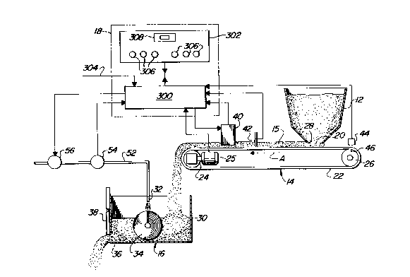
A sand and mixing system arranged in accordance with this
invention is shown schematically in FIG. 1. Sand is emptied
from a hopper 12 onto a conveyor 14 and emptied into a mixer
16. Water is added to the mixture in a quantity regulated by a
signal processing unit 18.
The conveyor 14 and sand hopper 12 cooperate to deposit and
transfer a uniform layer of sand 15 along the conveyor and into
mixer 16. An inventory of foundry sand is maintained in hopper
12. Sand from hopper 12 is channeled through an opening 20 at
the bottom of the hopper and directed onto a belt 22. Belt 22
i~ driven in direction A by frictional engagement with a head
roller 24. A variable speed motor 25 drives head roller 24
through an appropriate gearing mechanism. Belt 22 is continuous
and loops around head roller 24 and a tail roller 26, with both
rollers acting in opposition to maintain a desired amount of
tension on the belt. As the belt moves in direction A, sand is
carried away from opening 20 and under a striker edge 28.
Striker edge 28 maintains sand layer 15 at a depth of 16~
inches. As sand layer 15 advances over head roller 24, it drops
off belt 22 and into mixer 16.
Mixer 16 collects sand from the belt, mixes water with the
sand to adjust its moisture content and allows sand to be
withdrawn at a controlled rate for use in molds or forms. In
simplified form the mixer consists of a containment vessel 30, a
nozzle 32 through which water is directed into the mixer and a
wheel and plow assembly 34 for mixing the sand and water. Sand
is withdrawn through an opening 36 at one end of the mixer. A
movable door assembly 38 regulates the withdrawal of the sand
and water mixture from the hopper, with the withdrawal of sand
-- 5 --
~300~39
1 being intermittent or continuous. A motor assembly (not shown)
drives muller wheels 34 as water from a high pressure supply
(not shown) is piped to nozzle 32 by a conduit 52 and directed
into the mixer at a volumetric rate determined by the
hereinafter described signal processing unit.
Signal processing unit 18 has three basic functions:
receiving measurments of the physical properties of sand
entering the mixture; using these physical properties to
calculate the necessary water addition to the mixer to achieve a
desired sand moisture content; and delivering acontrol signal
for regulating the addition of water to the mixer, so that water
is supplied in the required amount. The signal processing unit
monitors and controls the sand moisture content through a series
of electrical signals. These signals are generated or received
by sensors and electro-mechanical control devices located about
the system.
Signals indicative of the sand properties are obtained from
sensors 40 that measure the electrical resistance of the sand
and sensors 42 that measure sand temperature. FIG. 2 shows a
section 200 of conveyor 14 over which sensors 40 and 42 are
located. Conveyor section 200 consists of side members 202 and
204 which are welded together about a support member 206 to
define a conveyor channel. A segment 208 of belt 22 slides on
top of suppoet plate 206 and extends across support plate 206 to
about the edges of side plates 202 and 204. A sand layer 210
rests on top of belt 208 for movement therewith. The width of
the sand layer is controlled by side plates 202 and 204, which
maintain the sand layer at a relatively uniform width of 37
inches. A support frame 212, attached to the outside of side
plates 202 and 204, spans the top of sand layer 210. Sensors 40
consist of two rectangular steel plates 214, 216 which are
suspended from support frame 212 and extend approximately ten
inches into sand layer 210. Plates 214 and 216 are spaced six
inches apart and have a width of eleven inches. A set of
lateral supports 218 and 220 prevent transverse movement of
plates 214 and 216 respectively. Each support 218, 220 is
welded to an outer face of its associated plate, outer being
taken to mean away from the center of the sand layer, and an
upper corner of support frame 212. A power supply cable 222 is
conductingly attached to the top edge of plate 214. A power
'
~ ' ' - .
~: .
.
1300339
1 output cable 224 is conductingly attached to the top edge of
plate 216. The opposite ends of power cables 222 and 224 are
connected to signal processing unit 18 and used, in a manner
hereinafter described to establish an electrical circuit across
the section of sand layer 210 between plates 214 and 216. Frame
212 is made of a nonconductive material such as wood or plastic
to prevent the frame from shorting plates 214 and 216. Ahead of
frame 212 a support structure 226 is attached to the outsides of
side plates 202 and 204 and suspends sensors 42, over the sand
layer. Sensors 42 comprise a set of three contact thermocouples
228, 230, 232. A flange 235 is positioned parallel to the sand
layer and has three thermocouples secured thereto. Flange 235
is part of folded plate 234 which extends upward and is attached
to the top of support structure 226. A backing plate 236
extends downward from the top of support structure 226 to
stiffen support plate 234. Frame 212 and structure 226 are
spaced close together so than sensors 40 and 42 are separated by
less than the width of belt segment 208. A pair of stabilizer
bars 238 and 240 extend from opposite sides of frame 212 and to
opposite sides of plate 234. The stabilizer bars reduce
deflection of the thermocouples under the drag loading of the
passing sand layer. The probe ends of thermocouples 228, 230
and 232 are shown by dashed lines 242, 244 and 246,
respectively. As shown by the drawings, these probe ends have
different lengths so that they extend to different depths within
the sand layer. A cable and conduit arrangement 248 connects
the thermocouples with the signal processing unit 18.
A sensor, positioned adjacent tail roller 26, measures the
speed of the sand layer by monitoring the belt speed. This
sensor consists of a proximity switch 44 located slightly above
tail roller 26 to sense the passing of a probe 46 located on the
periphery of tail roller 26. Therefore, revolutions of the tail
roller which has a diameter of 18 inches are monitored to obtain
a belt speed input. Monitoring the revolutions of tail roller
26 provides an accurate measurement of the belt speed since
there is negligible slip between belt 22 and tail roller 26. A
signal indicating the time for one revolution of the tail roller
is obtained from proximity switch 44 and received by signal
processing 18.
- 7 -
. `
i300339
Signal processing unit 18 also monitors the flow rate of cater
through conduit 52. A turbine type flow meter 54 positioned across
¦ conduit 52 sends a electrical signal indicative of the flow rate to
signal processing unit 18. Signal processing 18, in a manner
hereinafter described, generates a water control signal indicating
whether flow to nozzle 32 should be increased or decreased. A control
valve 56 is positioned across conduit 52 and receives thee water
control signal. Control valve 56 is a solenoid operated
electricomechanical flow control valve.
10Looking in more detail at the signal processing unit, this can
consist of any electronic data processing system that is capable of
receiving electronic signals from the sensors and sending electronic
signals to the control device. In this embodiment the signal
processing unit consists of a standardized industrial controller 300
that interfaces with an operator panel
302.
Controller 300 is a PLC 2/30 made by Allen Bradley (PLC is a
registered trademark of the Allen Bradley Co.) A series of
input/output modules are included with the controller for converting
and scaling analog signals that enter the controller into digital form
and digital signals leaving the controller into analog form. The
controller 300 has a remote power supply 304 for providing the
necessary power for the sensors and control devices. In particular,
controller 300 delivers a 6.57 volt supply to the conductive plates
and uses a 0-20 millamp sensor to measure the amperage across the
plates of sensor 40. Electrical signals from flow recorder 54, motor
25, theremocouples 42 and proximity switch 44 are also received by
controller 300. The signals are processed within the controller which
generates and sends the water output signal to' control valve 56.
Controller 300 executes a set of program steps, as hereinafter
described, to generate the signal for control valve 56. In addition,
controller 300 performs a series of data checks on the signals from
the various signals. The controller receives additional input for
performing the calculations and transmits data check information to
control panel 302.
Control panel 302 contains a series of warning lights 306 and a
thumbwheel control 308. When one of the signals, checked by
controller 300, is out of tolerance, a corresponding warning light on
control panel 302 is energized. The thumbwheel control
.
- .
13003:~9
1 308 is positioned by the operator to send an digital signal to
the controller that ultimately controls the moisture content of
the sand in the mixer.
The program steps or algorithim executed by controller 300
are set forth in flow chart form in FIG. 2. Acronyms for the
various input and output signals, which appear throughout the
specification and flow chart have the followig definitions:
BP = signal indicating that motor 25 is running
THR = thermocouple signal representing average sand
temperature in degrees Fahrenheit
PS = signal indicating input voltage to plates 4Q
PC = signal corresponding to output current from sensor 40
in milliamperes
FR = flow rate of water input from meter 54
PX = input from proximity switch which is equal to the time
in seconds for each revolution of tail roller 26
SMC = value obtained from thumbwheel which is scaled to equal
100 times the selected moisture content percentage
CVS = signal to control valve.
The algorithim begins with step 100. In step 101, BT, which
is used to monitor the belt operation, is assigned a value of
zero. At step 102, BP is read to determine if motor 25 is
running and more generally if the system is on. An input module
of controller 300 assigns BP a value of zero when the belt power
25 i8 off and a value greater than zero when belt power is on.
Step 103 checks whether the power is being supplied to the
belt. If not, BT is again initialized to zero in step 104.
Decision step 105 transfers the sequence to steps 106 if BT is
not greater than zero. Step 106 uses an appropriate timing
device to delay the program for five seconds and generates a
signal for energizing a warning light in step 206. The warning
light remains lit during the five second delay period to
indicate that the belt is not running. The five second
interval is used at this point to give the belt and sand layer
enough time to reach steady state after the system is initially
turned on. After five seconds BT is assigned a value of one in
statement 107 and the program returns to 102 to again check if
the belt is running. Once the belt has run for at least five
seconds, BT retains a value greater than 1 and the program goes
from step 105 to step 108.
.
~300339
1 Sensor inputs THR, PS, FR, PX and DMC are read in step 108.
The sensor inputs are then checked in the succeeding series of
steps for out of tolerance values. In step 109, TH~, is checked
to make sure the sand input temperature is between 60F and
170F. PS is checked in step 112 for minimum and maximum values
of 6 and 7 volts, respectively. The amperage output value, PC,
is checked in step 116 for a reading in the range of 1.6 to 16
milliamps. Flow recorder input FR is checked in step 120 for a
value of 0 and 60 gallons per minute. Finally, SMC is checked
to see if it is between 110 and 500, which represents a moisture
content between 1.1% and 5.0%. If any of inputs THR, PS, PC, FR
or SMC are out of tolerance, then steps 110, 114, 118, 122 or
126, respectively, will energize an appropriate warning light in
light set 206. Regardless of errors in the input, the program
continues onto step 128.
Step 128 uses an empirically derived equation to calculate
the moisture content of the sand on the belt, MCB. This
equation was empirically derived by sampling the moisture
content of sand passing between the plates and plotting the
moisture content as a function of the resistance across the
plates. The coefficient 12.5 and the constant 55 were used to
define a linear function that would approximate the moisture
resistance curve. Thus, a similar approach can be used to
derive suitable linear coeffients and constants for systems that
do not match the belt and sensor geometry of the system
described herein. Furthermore, the linear function was used in
this embodiment for the sake of simplicity; however, the
accuracy of the moisture content calculation may be improved in
other applications by the use of a higher order, curve fitting
equation. In addition, resistance is influenced by the sand
composition and temperature. Therefore, a more general sand
moisture equation could be derived having factors or variables
for different types of sand and variations in sand temperature.
Inclusion of such variables in the equation of step 128 were not
necessary for this preferred embodiment since the sand used
herein is ordinary foundry green sand and the sand tempeature
usually falls in a range of between 80F and 160F.
Another emperically derived equation, set forth in step 130,
computes the additional moisture content, AMC, that is necessary
to compensate for evaporative losses and provide suitable
-- 10 --
'
.
,
.
~3003~9
1 molding properties at the measured temperat~re. Again this
relationship is emperically derived and based on the specific
conveyor-mixer arrangement of this embodiment which allows about
10 minutes to elapse between the time that the sand properties
are measured and the sand is finally used in the mold. The
basic form of the equation in step 130 is a well known
relationship for adjusting sand moisture content with
temperature to obtain suitable molding properties. It is only
the constant, 50 and the coefficient of 1/100 that were adjusted
to provide suitable moisture content compensation for the system
herein described.
In step 132 the desired flow rate, DF, is calculated by
subtracting MCB and AMC from the selected moisture content of
the sand, SMC, and dividing the sum by PX to obtain a rate. The
- 15 coefficient 1.2 in step 132 is based on the geometry of the
system herein described and contains the necessary volume and
rate factors for converting the moisture content percentage and
belt timing values into a gallons per minute value.
In step 134, the desired flow rate is compared with the
actual flow rate. If the desired flow rate is less than the
actual flow rate, the routine goes to step 136 which decreases
the digital count for the control valve signal, CVS. If the
desired flow rate is greater than the actual flow rate, the
routine goes to step 138 wherein the digital count for the
control valve is increased. One of the hereinbefore described
modules scales the value of CVS such that a digital value of 200
will generate a signal for fully closing control valve 56 and a
digital value of one thousand will generate a signal that fully
opens control valve 56.
In step 140, the routine is delayed for a 100 milliseconds
by a suitable timing device before returning back to step 102
and continuing the loop. The program then loops from step 140
to step 102 to check that the belt remains running. The delay
of 100 milliseconds can be extended for other applications if
hunting of the flow control valve becomes a problem.
The flow chart of FIG. 2 describes the operation of the
program in a general way which can be converted to a machine
language and implemented by those skilled in the art. In
addition, this description has set forth a specific
configuration for the mixer, conveyor and control apparatus.
13003~9
1 This specific arrangement includes structural details, control
system details and operating parameters that may be varied in
order to tailor the system of this invention to other
applications. For instance, it may be desirable to have the
sensed parameters recorded for later retrieval and review.
Furthermore, it may be advantageous to replace the control board
with a CRT terminal which could display all input and output
values. In light of the foregoing description, those skilled in
the art will be aware of these and other alternatives,
modifications and variations that may be available in practicing
this invention. Accordingly, this invention is intended to
embrace all such alternatives, modifications and variations
which fall within the spirit and scope of the appended claims.
- 12 -