Note: Descriptions are shown in the official language in which they were submitted.
~3e:~05Z9
This invention relates to a fle~ible case hanging
device, and more particularly to a hanging device for
hanging and extending an inner bag in a transport container.
Inner bags have been used in containers to prevent
articles or goods therein from being contaminated during
transport. The inner bag is hung from the inner walls of
the container by means of hangers so as to be extended as
wide as possible in the container. The articles or goods
are accommodated in the inner bag and transportea.
According to the present invention there is provided
a flexible case hanging device comprising a belt memb~r
having one end fixed to a side edge along one edge of a
corner of a case and a free end anchored by a buckle
provided on a side edge along the other edge of the corner,
and an annular body provided at a vertex o~ said co~ner,
part of said belt member passing through said annular body
to form a loop of the belt member, which is adjustable into
smaller sizes by pulling said free end of the belt member.
.. . . . . ... . . . . .
In a preferred embodiment, the device further
comprises an auxiliary fastener which comprises a belt
cloth fixed to a side edge along an edge of the case, an
annular hody fixed to the belt cloth, a buckle fixed to the
belt cloth on a side opposite to the annular bGdy and a
belt member having one end fixed to the belt cloth between
the annular body and the other free end anchored by the
buckle, part of the belt member passing through the annular
body to form a loop of the belt member, which is adjustable
into small sizes by pulling the free end of the belt member.
In hanging and extending a flexible case by the
hanging device constructed as described above, the loop is
directly or indirectly fixed to an aktaching portion of,
for example, an inner wall of a container, and the ~ree end
of the belt member is fixed by the buckle. Therefore, the
side edges on one side and the other side are supported
~L3~SZ9
through the belt member, and vertexes of corners of the
case are supported through annular bodies to distribute the
supporting force, thereby enabling the flexible case to be
hung and extended with mitigated stress concentration.
Moreover, as the free end of the belt member is
pulled to make the loop of the belt member smaller, the
side edges on one side and the other side of the case and
the vertex o~ the corner of the case can be pulled to
eliminate or prevent slack of the case.
BRIEE' DESCRIPTIO~91 OF ~E DRAWIl~GS
The invention will be more fully understood by
referring to the following detailed specification and
claims taken in conjunction with the appended drawings.
Fig. 1 is a perspective view illustrating an inner
bag for a container according to one example of the prior
art;
Fig. 2 is a perspective view showing a principal
part of an inner bag for a container to which is applied
one embodiment of the invention;
Fig. 3 is a perspective view illustrating one
embodiment of the invention; and
Fig. 4 is a perspective view illustrating a
preferred example of an auxiliary fastener.
Fig. l is a schematic perspective view illustrating
a hitherto used inner bag for a container having hangers
~for example disclosed in Japanese Laid-open Patent
Application No. 49-105,686).
The inner bag shown in Fig. l comprises an upper
surface lO, a bottom surEace 12, a rear surface 14, side
surfaces 16 and 18 and a front surface 20 to form a
hexahsdron, and further comprises hangeirs 22 and 24 and
dump-up fixtures 26 for connecting the inner bag to the
--2--
31 3~SZ9
inside of the container. The inner bag includes charging
openings 28 and a small discharging opening 30. Reference
numerals 32 and 34 denote a screen canvas and a skirt
canvas which form the front surface 20.
The hangers 22 and 24, usually in the form of hooks
or strings, are independently provided on side edges along
edges of ths inner bag; on the other hand mounting portions
are provided on the inner walls of the container
correspondingly to these hangers 22 and 24. In arranging
and extending the inner bag in the container, the hangers
22 and 24 are hung on or fastened to the mounting portions
of the container.
With such hangers for a case or bag, however, it is
impossible to remove or prevent slack of the case or bag
occurring when the bag is extended in a container.
In these hangers, moreover, the case or inner bag is
hung from the inner walls of the container at several
points of the bag so that, upon being subjected to load, it
tends to cause stress concentration at the supported points
. .
of the bag resulting in damage or breakdown of the bag.
For inner bags of containers, particularly, ropes
are often provided on upper surfaces of the inner bags for
preventing slack in the inner bags. However, the use of
such ropes in addition to the hanging means causes a new
problem because construction is therefore complicated.
It is an object of the invention to provide a
flexible case hanging device which eliminates all the
disadvantages of the prior art and which is able to
eliminate or prevent slack of a flexible bag and mitigate
stress concentration occurring at hung portions of the case.
DETAILED DESCRIPTION OF PREFERRED EMBODIME~TS
The attached drawings for explaining the invention
are schematic so that the in~ention can be understood and
it will be appreciated that shapes, dimensions and
positional relations bekween the respective components of
~3alaSZ9
the invention are not limited to those shown in the
drawings.
Fig. 2 is a perspective view of a principal part of
an inner bag for a container having the hanging device as
one embodiment of the invention. This embodiment applied
to the inner bag for the container will be explained
hereinafter.
Referring to Fig. 2, reference numerals 38, 40 and
42 denote a front surface, a side surface and an upper
surface of the container inner bag ~referxed to hereafter
as only "inner bag") to form a substantial heæahedron in
the same manner as in the inner bag of the prior art.
Moreover, reference numeral 44 denotes an opening of
the inner bag, which is covered by a cover member 46.
Although the constitution of the inner bag is not limited
to that shown in the drawing, the inner bag of this
embodiment is provided with the opening 44 at the upper
part of the front surface 38 and with the cover member 46
extending from an upper end of the opening 44. The opening
44 is opened and closed by opening and closing the cover
member 46. Reference numeral 48 in the drawing illustrates
fastening means, for example, magic tape (trade name).
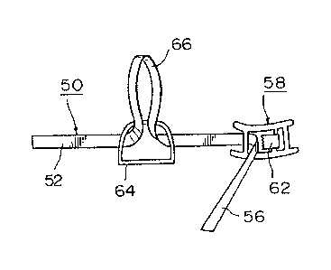
Fig. 3 is a schematic perspective view illustrating
one embodiment of the invention.
In Figs. 2 and 3, a belt member 50 has a fixed end
52 fi~ed to a side edge along one edge, for example, edge a
at a corner of a case, for example, an inner bag of a
container.
In the embodiment shown in the drawings, the fixed
end 52 is fixed to the side edge along the edge a on the
upper side of the front surface 38. In other words, the
hanging device according to this embodiment is provided at
an upper corner of the ront surface 38. Moreover, the
fixing means for the fixed end 52 of the belt member 50 may
be any suitable means, such as sewing, welding, adhering or
sz~
the like. Reference numeral 54 denotes a belt cloth which
in this embodiment is fixed to the side edge along the edge
a by sewing in order to reinforce the side edge of the
inner bag. Therefore, the fixed end of the belt member 50
is fixed to the side edge through the belt cloth 54.
Moreover, a buckle 58 is provided on a side edge
along another edge, for example, the edge b of the corner
for anchoring a free end 56 of the belt member 50.
In the illustrated embodiment, the belt cloth 54 is
also fixed to, for example, the side edge along the edge b
at the upper end of the side surface 40, and the buckle 58
is fixed to the belt cloth 54 through a belt member 60.
The buckle 58 is provided with a stopper 62 which is
inoperative when the ree end 56 of the belt member 50 is
pulled in a direction as shown, for example, by an arrow P
such that the free end 56 is not anchored. On the other
hand, when the free end 56 is pulled in a direction shown
by an arrow Q opposite to the direction P, the stopper 62
is operative to anchor the free end 56 of the belt member
50.
Moreover, an annular body 64 is located at a vertex
of the corner. Part of the belt member 50 passes through
the annular body 64 to Eorm a loop 66 which is adjustable
to a smaller loop by pulling the free end 56. The "vertex
of the corner" referred to herein means a point of
intersection of the ed~es (for example, the edges a and k)
at the corner and the corner itself in the proximity of the
point of intersection.
In the illustrated embodlment, the annular body 64
is also fixed to the vertex of the corner through the belt
member 60. The part of the belt member 50 between the
fixed and free ends 52 and 56 is partially extended through
the annular body 64 to form the loop 66. In this
em~odiment, the loop 66 is connected through a fastening
ring 68 to an attaching portion (not shown~ on an inner
wall of the container.
--5--
"
~3~S~9
With the hanging device provided at the corner oE
the inner bag of the container as above described, when the
free end 56 is pulled in the direction P, the length of the
belt member 50 extending from the buckle 5B to the fixed
end 52 is shortened to make the loop 66 smaller. As a
result of the reduction of the diameter of the loop 66, the
side edges of the inner bag along the edges a and b can be
pulled toward the vertex of the corner to which the annular
body 64 is fixed, respectively, because the loop 66 is
connected through the fastening ring 68 to th~ attaching
portion on the inner wall of the container. Furthermore,
the free end of the belt member 50 is pulled in the
direction P to make the loop 66 smaller to cause the vertex
of the corner to approach the attaching portion on the
inner wall of the container.
In hanging and extending the inner bag in a
container, therefore, the loop 66 of the belt member is
made smaller to give tension to the inner bag so as not to
cause any slack, thereby eliminating or preventing the
slack of the bag. Accordingly, complete support of the
inner bag and removal and prevention of slack of the bag
can be accomplished with the simple construction without
requiring any slack-preventing rope as used in the prior
art.
Moreover, as the inner bag is supported at locations
where the buckles 58, the annular bodies 64 and the fixed
ends 52 of the belt members 50 are fi~ed, to avoid the
point support of the bag as in the prior art, it is
possible to mitigate the stress concentration which would
cause damage or breakdown of the inner bag.
Fig. 4 is an enlarged perspective view illustrating
an important part of the lower portion of the inner bag of
the container shown in Fig. 2. In order to make the
invention more effective, an auxiliary fastener shown in
Fig. 4, to be explained hereinafter, is preferably provided
~.3~0S2~
on the inner bag of the container. Corresponding parts to
those in Figs. 2 and 3 are designated by the same re~erence
numerals as those in the previous embodiment and will not
be described in more detail.
In Fig. 4, the auxiliary fastener 70 includes an
annular body 64 fixed to a belt cloth 54 which is fixed to
a side edge of an inner bag along a lower edge c of a side
surface 40, and a buckle 58 fi~ed through a belt member 60
to the belt cloth 54. Moreover, a fixed end ~2 of a belt
member 50 is fixed to the belt cloth 54 between the buckle
58 and the annular body 64, and a free end 56 of the belt
member 50 is held by the buckle 58. A part of the belt
member 50 between the fixed and free ends 52 and 56 forms a
loop 66 with the aid of the ann~llar body 64. In this case,
the loop 66 is connected through a fastening ring 68 to an
attaching portion on the inner wall of the container.
By this arrangement, when the free end S6 is pulled
in a direction shown by an arrow P', the buckle 58 is moved
toward the annular body 64 provided at the vertex of the
corner. The loop 66 is connected to the attaching portion
on the inner wall of the container. Following to the
buckle 58, therefore, the side edge of the inner bag along
the edge c is urged towards to the corner, thereby applying
tensile force to eliminate or prevent slack of the bag
along the edge c. A direction shown by an arrow Q' in
Fig. 4 is along the belt member 50 and opposite to the
direction P'.
By providing the auxiliary fastener and the hanging
device in the above embodiment on any suitable corners of
an inner bag for a container, the slack of the bag is
eliminated or prevented, while the inner bag is simply and
quickly hung and extended in the container.
Q5:2~
This invention is not limited to the above
embodiments, and configurations, positional relations,
fixed positions and fixing means of the belt members,
annular bodies and buckles may be modified favorably at
will depending upon requirements in designing.
Eor example, any buckles having different
construction from those of the buckles shown may be us~d so
long as the belt member can be pulled in one direction such
as the direction P or P', but cannot be pulled in the other-
direction, as the direction Q or Q'. For example, a buckle
for a belt for trousers may be used.
The annular body may be of any annular shape so long
as it is able to form a loop of a belt member passing
through the annular body. The belt member may be
ribbon-shaped strap, mesh strap or any other shaped belt
members.
This invention may be applied to various kinds of
cases or bags, for e~ample, inner bags for containers,
vessels in the form of mosquito nets and other cases.
Moreover, the fastening ring my be of any suitable
construction without being limited to that shown in the
embodiments.
As can be seen from the above description, the case
hanging device according to the invention can eliminate or
prevent the slack of the case or bag when it is being hung
and extended, and mitigate the stress concentration caused
at parts of the bag being hung.
While the invention has been particularly shown and
described with reference to preferred embodiments thereof,
it will be understood by those skilled in the art that the
foregoing and other changes in form and details can be made
therein without departing from the spirit and scope of the
invention~