Note: Descriptions are shown in the official language in which they were submitted.
- CONNECTOR FOR RELEASABLE SECUREMENT TO THE FR~E END OF A
LIFTING STRAP
Backqround of the Invention
This invention relates to new and useLul improvements
in connectors and is particularly concerned with a strap
connector.
Various components, such as modular building sections,
are frequently handled by cranes or the like which use cables
or straps with heavy and bulky hooks or the like on the ends
thereof. Such components must be provided with a rather
large space underneath and between them in order to pull out
the lifting line and hooks. The components must then be
brought together after the lifting lines are removed.
Obviously, any material spacing requires considerable extra
work in bringing the components into abutment for connection
and such comprises a disadvantage of systems that use hooks.
Another disadvantage of systems that use hooks or the like,
is that they frequently damage the components.
Straps have heretofore been used as lifting lines in
view of their versatility, namely, they are easy to handle,
they can be manufactured with great tensile strength, and
they do minimum damage to components around which they may be
engaged. Generally, these straps are provided in specific
lengths designed to accommodate specific components to be
lifted and have the undesirable opposite end hooks or the
like arranged for releasable connection to lifting mechanism.
~ .
:3~
667
--2--
Summary of the Invention
A primary objective of the invention is to provide
a connector for the releasable securement of one end of a
lifting strap thereto whereby the connector allows strapping
to ~e engaged with a component to be lifted and by its
structure allows the strap to have a free unobstructed end so
that the strap can be pulled free of the component through a
minimum space.
Another object of the invention is to provide a
10 connector of the type described which has a simplified struc-
ture, which is simple in operation, and which allows a
lifting assembly to handle components with substantially
one strap length.
In carrying out the objectives of the invention, the
connector comprises a body portion having opposite ends and
a hollow interior and including stationary anchor means in
the body portion arranged to receive a free strap end portion
capable of releasable securement thereto. The anchor means
is arranged to provide a support on which the free end por-
tion of the strap is pinched under a lifting portion thereofby a lifting force. Releasable pin means are provided in the
body portion and arranged for insertion in the loop of the
looped end of the strap for positioning the loop in its
pinched secured position on the body portion and for release
from said body portion when it is desired to disconnect the
strap from the connector. The body portion includes ratchet
' ~
t~ke-up shaft means arranged to take up e~cess of the free
strap end. The stationary anchor means ~referably com-
prises a cross bar having a knurled surface. The length o~
strap used with the connector may be of maximum length
whereby to handle substantially most components, any excess
strap merely being unused as a free end.
The invention will be better understood and additional
objects and advantages will become apparent from the
following description taken in connection with the accompany-
lO ing drawings
Brief Description of the Drawinqs
Figure 1 is an elevational view showing a function of
the invention, namely, providing a connection for a strap ln
a lifting operation for modular building sections;
Figure 2 is a perspective view of a connector embodying
features of the present invention;
Figure 3 is a side elevational view of the connector;
; Figure 4 is a view similar to Figure 3 but partly broken
away to show internal structure; and
Figurs 5 is a front edge view oE the connector.
Detailed Descri tion of a Preferred Embodiment
. P
With particular reference to the drawings, the numeral
10 designates the body portion of the present connector.
This connector is designed for use with conventional
25 strapping 12 arranged to have one end secured to a crane
operated lifting assembly 14. The assembly 14 has a spreader
--4--
16 to which is secured a lifting cable 18 in turn secured tothe present connector 10. Figure 1 shows as an e~ample the
present connector and strap 12 as well as lifting assembly 14
in conjunction with handling building modules 20, wherein
these modules are set in place in close relation. It is
to be understood, however, that the invention may be used
in connection with the handling of other components as well
such as containers, vehicles, etc.
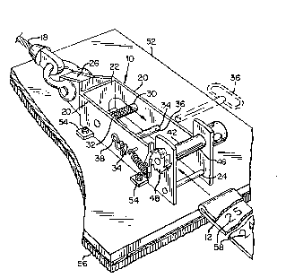
Connector 10 comprises a pair of parallel side walls
20 defining an opening at the lower end and integrated into a
rugged structure by a top wall or connecting portion 22 and
one or more reinforcing cross rods 24. The top wall 22 has
an extension 26 for suitable connection to the lifting cable
18.
l~ A heavy duty cross bar 30 is secured between the side
walls 20 in an upper part of the body portion but in spaced
relation to the top wall 22. This bar is also spaced
between the edges of the side walls. The surface
32 of cross bar 30 is knurled for a reason to be described
hereinafter. Cross bar 30 also contributes to rugged
reinforcement of the walls 20.
Each of side walls 20 has an aperture 34. These
apertures are in alignment with each other and arranged to re- .
leasably receive a pin 36 capable of being locked in place
by a cotter 38. Apertures 34 are spaced from the bar 30 in a
direction toward the open or bottom end o~ the connector
and are also spaced between the side edges of the connector.
A strap take-up shaft 42 has journaled support in
extensions 44 extending from one edge of the side walls
at the bottom end of the connector. Shaft 42 has a diametral
slot 46 capable of slidably receiving the strap and has
selected controlled rotation by a ratchet mechanism 48
operative on the shaft.
Connector 10 can be integrally attached edgewise to a
rigid baseboard 52, as by connecting ears 54 on the side
walls 20. The opposite surface 56 of the baseboard from
the connector supported surface is cushioned.
In the operation of the present connector for
association with a component 20 to be lifted, it is
located by means of a crane operated assembly 14
adjacent the component, the cushioned surface 56 of the
baseboard 52 facing the component. The free end of the
strap is brought down the one side opposite from the
connector and under the component. It is then attached to
the connector as follows: With the slack in the strap
between the spreader 16 and the connector being manually
taken out, the free end of the strap, designated by the
reference character 12a in Figure 4 is doubled back on a
lifting portion 12b thereof. The doubled back portion
is made of a sufficient length such that it can extend
over the cross bar 30 with its looped portion, designated
by 12c, and at least down as far as the apertures 34.
' r ~
~.~Q¢~
--6--
At this time, the pin 36, which has been previously removed,
is then inserted in apertures 34 and through the loop 12c.
Also at this time or before if desired, the loose or free end
12a is threaded through the slot 46 in the take-up shaft.
The unused end of the strap will merely hang free. In the
process of pulling the unused end through the slot in the
take-up shaft, sufficient slack is left in the strap bet~een
the pin 36 and the take-up shaft such that at least two wraps
can be taken on the shaft whereby to provide a positive hold
of the strap on the shaft. The slac~ is then taken out of
this free span of the strap by ro-ating the shaft ratchet
with control.
The strap is provided with length indicia 58 thereon
giving the length of the strap from the connecting point
of the strap with the lifting assembly 12. Such can be used
as a guide in its engagement with the connector 10, for
example, when more than one strap is used, they can be
readily attached to the connector 10 at equal lengths.
As the connector is lifted by the crane and a load is
thus put on the lifting end 1~b of the strap, this portion of
the strap bears down on the free end of the strap and pinches
it against the cross bar 30, thus providing a positive
non-sliding frictional connection for said free ~nd. The
wrapping of the free end of the strap on the take-up shaft
insures a greater positive securement of the strap to the
connector but generally is not necessary for the hold on the
strap. Knurled surface 32 of the cross bar 30 proviAes a
good grip on the strap.
~ hen the component th~t is being handl3d has been set in
place, it is merely necessary ~o releas2 the free end of the
loosened strap from the take-up shaft and to remove the pin
3~. Since the free end of the strap does nat have any
obstruction thereon, it can be readily pulled out from under
; and up the side of the component. With the present system,
components ara capable of being set closely together and thus
readily r-moved into abutting relation in a final structur-
ing step. With the use of the present inventlon, a strap
can be of a length to accommodate substantially all com-
ponents to be handled since any excess strap length is
merely taken up in the connector as a free unused end.
It is to be understood that the form of my invention
herein shown and described is to be taken as a preferred
example of the same and that varous changes in the shape,
size and arrangement of parts may be resor-ed to without
departing from the spirit of my invention, or the scope
of the su~joined claims.