Note: Descriptions are shown in the official language in which they were submitted.
~ ~3~Q~3E~ti
-- 1 --
This invention relates to a method of manufacturing an
optical fiber-preform, and more particularly to a method of
manufacturing a preform for an asymmetrical optical fiber.
As used herein, the term "asymmetrical optical fiber" is
defined to mean that type wherein a common glass cylindrical
cladding contains a plurality of fihers prepared from the
glass having different properties from the cladding glass;
all the fibers act as core, or some of them function as
stress-applying parts; all the glass fibers are integrally
embedded in the cladding; and at least one of the plurality
glass fibers is positioned apart from the central axis of the
cladding. The conventional single mode optical fiber
contains only one core extending along the central axis of
cladding. In a~ymmetric optical fibres, one example of the
prior art has a core formed of glass having a larger
refractive index than that of cladding so as to cause light
beams transmitted through the core to perform substantially
total reflection at an interface between cladding and core.
Two cores are positioned apart from the central axis of the
cladding.
In one type of twin-core type optical fiber two cores
are spaced from each other to prevent light beams passing
therethrough from interfering with each other. This type can
be applied as a sensor, if the two cores are made to have
different properties. When external environmental factors
such as atmospheric temperature and pressure are applied to
the optical fiber changes appear in the state of light
transmitting through the cores. If the cores are made to
:
~3~886
-- 2 --
have different properties in advance, it is possible to
detect the magnitude of received external environmental
factors from the difference between the state of light in one
core and that in the other core.
In another type of twin-core optical fibre the two cores
are positioned near to each other and light transmitted
therethrough can be coupled together. Therefore, the twin-
core type optical fiber can be applied as a coupler or
isolator.
A ~econd example of asymmetrical optical fiber is
referred to as "a polarization-maintaining optical fiber." In
such a fiber only one core extend~ along the central axis of
the cladding. Two stress-applying parts are embedded
; lengthwise in the cladding. Stress-applying parts are
; 15 prepared from glass material having a larger thermal
expansion coefficient than the cladding.
The above-mentioned polarization-maintaining
optical fiber is characteri~ed in that even when light is
transmitted while the fibers are warped, the polarization at
the input end can be sustained eveD though light is
transmltted through a long distance. Therefore, the
polarization-maintaining optical fiber can be applied in a
wlde field including a sensor Iike a flber gyroscope and
coherent optical communication based on only a particular
polarization of light.
In obtaining an asymmetrical optical fiber, a preform
':
~which ia previously manufactured by the method described
below is elongated to have the predetermined diameter.
.
.
13~
-- 3
The conventional method of manufacturing a preform for
an asymmetrical optical fiber involves the rod-in-tube method
or pit-in-tube method. In one method a cladding-mother rod,
core-mother rod, stress-applying-mother rods are provided in
advance~ These mother rods can be produced by widely known
; processes such as VAD (vapor-phase axial deposition), OVPO
(outside vapor phase oxidation) and MCVD (modified chemical
vapor deposition).
Thereafter, holes for insertion of the core-mother rod
and the stress-applying-mother rod are perforated in the
cladding-mother rod by a drill. Each hole is referred to
7'drilled-pore" hereinafter. Later the core-mother rod and
stress-applying-mother rod are inserted into corresponding
drilled pore.
Heating is then externally applied to the cladding-
mother rod by means of, for example, a burner. Thus, the
boundaries between the inserted mother rods and cladding-
mother rod are fused together, thereby providing a perfectly
integrated transparent preform.
The conventional rod-in-tube process and pit-in-tube
process have the following difficultie First, limitation
has to be imposed on the slze of a preform to be obtained.
If it is attempted to obtain a long preform, a necessarily
long drilled-pore will have to be formed in cladding-mother
; 25 rod. However, no present technique CAn perforate such a long
drilled pore through a glass rod, thus imposing a limitation
on the length of preform to be fabricated.
: '
, ~,,
''
130~38~
-- 4
Secondly, impurity contamination or scratches tend to
appear on the inner wall of drilled pore or the surface of
the core-mother rod and the stress-applying mother rod.
Therefore, when the preform is drawn to provide an optical
fiber, an impurity may difuse into the core
; or bubbles will appear in the fiber. These events lead to
the transmission loss of light passing through the core.
This invention has heen accomplished in view of the
above-mentioned circ~mstances and is intended to provide a
method of manufacturing a preform for an asymmetrical optical
fibex, which can resolve the aforementioned difficulties
accompanying the conventional process and ensure the
manufacture of a long asymmetric optical fiber and can obtain
low transmission loss.
Accordingly, the invention is a method o~ manufacturing
a preorm for an asymmetrical optical fiber which comprises
the steps of:
; ta) fixing and assembling a plurality of
transparent glass rods in parallel xelationship in a pair of
jigs, to form a rod assembly, said plurality of glass rods
including at least one core-mother rod functioning as a core
in said optical fiber;
(b) depositing glass soot around said rod assembly
of said plurality of fixed glass rods by rotating said rod
assembly and spraying the glass soot on said rod assembly
while it is rotated, thereby forming a single porous glass
cladding which surrounds all the glass rods and has a
predetermined ~hape; and
'. . .
13~ 86
(c) removing said pair of jigs from said
txansparent glass rods and vitrifying said porous glass
cladding to a single transparent cladding by thermal fusion,
thereby forming an entire integral transparent preform which
can be drawn into an asymmetrical optical fiber, said
transparent cladding having a smaller refractive index than
said at least one core-mother rod~
This invention can be more fully understood from the
following detailed description when taken in conjunction with
the accompanying drawings, in which:
Fig. 1 illustrates the structure of the ordinary
symmetrical optical fiber;
Figs. 2A to 2C respectively set forth the various
asymmetrical optical fibers;
Figs. 3A to 3D show the conventional method of
manufacturing a preform for an asymmetrical optical
; fiber;
Figs. 4A to 4C indicate the sequential steps of
manufacturing a preform for the polarization-maintaining
optical fiker of Fig. 2C representing the present invention;
Fig. 5A to 5C set forth the sequential steps of
fabricating a core-mother rod lnvolved in the preform for
asymmetrical optical fiber used in the embodiment of Fig. 4A
to 4C;
Flgs. 6A and 5B indicate the refraction index profile
across the core-mother rod and stress-applying-mother rod
u ed in the embodiment of Fig. 4A to 4C.
.
.
,' ' ' ~ ' . ', ' ' -
~30Q~38~
- 6 -
Fig. 7 is an enlarged view of burner 66 indicated in
Fig. 4C;
Figs. 8A and 8B illustrate the manner in which glass
soot is deposited in Fig. 4C;
Fig. 9 shows the heating process for converting the
porous pr~form obtained in Fig. 4C into a transparent
preform;
Figs. 10 and 11 set forth the sectional view of a
polarization-maintaining optical fiber obtained from the
preform manufactured by the method of this invention;
Figs. 12 and 13 indicate the method for applying the
present invention to the manufacture of a preform for a twin-
core type optical fiber: and
Fig. 14 is a sectional view of a twin-core type optical
fiber obtained from a preform manufactured by the method
illustrated in Fig. 13.
Figs. l to 3D illustrate the prior art. Fig. 1, shows
the conventional single mode optical fiber containing only
one core 20 extending along the central axis of cladding 10.
Figs. 2A to 2C show an asymmetrical optical fiber. Fig.
2A or 2B represents a first example of an asymmetrical
optlaal fiber. Throughout the figures set forth, reference
numeral 10 denotes a cladding. Two cores 20 are lengthwise
embedded in cladding 10. Core 20 is~formed of the glass
- ~ ~25 having a ~larger refractive index than that of cladding 10 so
`~ as to cause light beams transmitted through cor~ 20 to
perform a substantially total reflection at an interface
' ~
, . ,
130(~
-- 7
between cladding 10 and core 20. Two cores are positioned
apart from the central axis of cladding 10.
Referring to the above-mentioned twin-core type optical
iber, the type of Fig. 2A wherein two cores 20 are spaced
from each other to prevent light beams passing therethrough
from interfering with each other, can be applied as a sensor
if two cores 20 are made to have different properties. when
; external environmental factors such as atmospheric
temperature and pre~sure are applied to the optical fiber,
changes appear in the state of light transmitting through
cores 20. If cores 20 are let to have different properties
in advance, it is possible to detect the magnitude of
received external environmental factors from the difference
~etween the state of light in one core and that in the other
core.
If two cores 20 are positioned near to each other as
shown in Fig. 2B, then light transmitted therethrough can be
coupled together. Therefore, as indicated above, the twin-
core type optical fiber can be applied as a coupler or
isolator.
Fig. 2~ shows a polarization-~aintaining optical fiber.
In Fig. 2C, only one core 20 extends along the central axis
of cladding 10. Two stress-applying parts 30 are embedded
lengthwise in cladding 10. Stress-applying parts 30 are
~25 prepared from glass material havlng a larger thermal
expansion coefficient than cladding 10.
" ~
':
:
.. . .
'. ~
- 7A -
The conventional method of manufacturing a preform for
an asymmetrical optical fiber is shown in Figures 3A to 3D.
As illustrated in Fig. 3A, cladding-mother rod 11, core-
mother rod 21, stress-applying-mother rods 31 are provided in
advance. Mother rods 11, 21, 31 can be produced by the
widely known processes.
Thereafter, drilled-pore 14 for insertion of core-mother
rod 21 and stress-applying-mo-ther rod 31 are formed in
cladding-mother rod 11 by means of drill 40.
Later as shown in Fig. 3C, core-mother rod 21 and stress-
applying-mother rod 31 are inserted into corresponding
;~ drilled pore 14.
As indicated in Fig. 3D, heating is externally applied
to cladding-mother rod ll by means of, for example, flames 44
of burner 42. Thus, the boundaries between the inserted
;~ mother rods 21, 31 and cladding-mother rod 11 are fused
together, thereby providing a perfectly integrated
transparent preform 90.
The preform for the twin-core type optical fiber shown
ln Figs. 2A and 2B is fabricated in the same manner as
mentioned above.
The conventional rod-1n-tube process and pit-in-tube
process are accompanied with the difficulties described
above. That is a long drilled-pore 14 will have to be
perforated in cladding-mother rod 11 and no technique exist
for forming such a long drilled pore through a glass rod,
::
: ~3QQ~;
- 7B -
Secondly, and again as indicated above, impurity
contamination or scratches tend to appear on the inner wall
of drilled pore 14 or the surface of core-mother rod 21 and
streæs-applying mother rod 31.
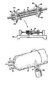
Figs. 4A to 4C collectively show a method of manu-
facturing a preform for a polarization-maintaining optical
fiber of Fig. 2C, embodying the present invention. According
to this embodiment, core-mother rod 21 and two stress-
applying-mother rods 31, 31 are first provided. These mother
rods are arranged parallel as illustrated in Fig. 4A, and
securely set by means of a pair of disc-shaped fixing jigs
58. Three rod-inserting holes 60 are perforated in a line in
disc-shaped paired fixing jigs 58. Core-mother rod 21 is
taken into the central rod hole, and stress-applying-mother
rods 31, 31 are inserted into two rod holes formed on both
sides of the central hole. Mother rods 21, 31, 31 are
securely set in place by bolt 6~ threadedly inserted radially
into di~c-shaped jig 58~
Above-mentioned core-mother rod 21 and stress-applying-
mother rods 31, 31 can be manufactured by the previously
described known processes VAD~ OVPO, and MCVD.
It is desired for the reason given below that the core-
mother rod 21 contains predetermined thickness of
.
:: :; :
~ ~`'' .
, ~ ' .
- ,~ .
~3~0886;
-- 8 --
cladding portion integrally wraps core portion. De-
scription may now be given with reference to Figs. 5A
to 5C of the VAD process of forming core rod 21.
Referring to 5A, reference numeral 46 rapresents a
burner for core soot. Raw gas 48 of core soot is sup-
plied to burner 46. The core soot resulting from the
reaction of the raw gas is sprayed and deposited on a
support plane (not shown) which constitutes the distal
end face of a quartz rod, thereby providing core-soot
deposited rod 22a. Reference numeral 50 is a burner
for ejecting cladding soot. Burner 50 is supplied with
raw gas. The cladding soot generated by the reaction
of raw gas is sprayed and deposited on the surface of
rotating core-soot deposited rod 22a, thereby providing
cladding soot deposited layer 22b. A deposited mass
o~ glass soot is thermally dehydrated in a furnace by
applying a proper dehydrant such as SOC~2. Heating
temperature applied at this time is defined to be lower
than that level at which core soot and cladding soot
are fused to render deposited layers 22a, 22b are
~vitrified. Later, the preliminarily heated mass is
held ln tubular furnace 54~provided with heating means
56 ~Flg. 5B~ . In th~is tubular~furnace, the whole mass
is~ turned into a transparent~glass-like state. A glass
:, :
bar produced in tubular furnace 54 is elongated to the
predetermined diameter, thereby providing core~mother
rod 21 (Fig. 5C).
,~
~,, :.
,
: : ,
~3~
g
Fig~ 6A indicates the refraction index profile
across core rod 21 and glass composition thereof. As
seen from the illustration, the refraction index
(1.4643) of the core portion is made larger than that
(1.457) of the cladding portion in order to ensure the
prescribed property of an optical fiber. To attain the
above-mentioned distribution of refraction index, the
core portion is prepared from fused silica doped with
germanium, and the cladding portion is composed of pure
fused silica.
The cladding portion of core-mother rod 21 has a
function of preventing the OH group released during the
steps later described with reference to Figs. 4B and 4C
from approaching near the core portion. The reason why
lS the intrusion of the OH group should be prevented is
that the ~olarization-maintaining optical fiber is
generally applied in the single mode. Namely, in the
single mode, the cladding near the core also takes
part in assisting the transmission of light beams.
If, therefore, the OH group is retained in the neigh-
borhood of the above-mentioned cladding near the core,
light beams is noticeably absorbed, resulting in a
large transmission loss. The aforementioned dehydra-
tion of the glass soot structure during the fabrication
of core-mother rod 21 is intended to exclude the OH
group from core-mother rod 21.
The cladding portion of the core-mother rod should
~,
13~0886
-- 10 --
have a certain thickness in order to fully exhibit its
function. If the cladding portion is made underly
thick, the undermentioned difficulties will arise. When
an optical fiber shown in Fig. 2C is fabricated, an
asymmetrical stress exerted by stress-applying parts 30
does not reach core 20, thus failing to ensure a full
polarization effect. If~ therefore, this fact is taken
into account, it is preferred that cladding portion
should have such a thickness as corresponds to about 4
times the diameter of core portion.
Stress-applying-mother rod 31 can also be prepared
by the aforementioned V~D process. However, stress-
applying parts 30 should have a larger thermal expansion
coefficient than cladding 10. Further, as seen from the
refractive index profile of Fig. 6B, stress-applying-
mother rod 30 should have a smaller refractive index
than cladding. When, therefore, cladding is formed of
pure fused silica, and stress-applying rod 31 is pre-
pared from fused silica, then it is advised to apply
dopants capable of reducing the refractive index, for
example, boron or fluorine. I~n this inv~ntion, the
dopant concentration is defines to the about 15-20 mol%
:
;in the case of boron and about 2 mol% in the case of
fluorine. Further, if required, germanium, too, may be
applicable as a dopant. The dopant concentration of
; germanium is defined to be about 5-6 mol%, under the
condition in whlch the refractive index does not become
larger than in the case of pure silica.
An assembly of mother rods fixed in the afore-
mentioned manner is fitted to glass lathe 64 shown in
Fig. 4B. While the assembly is rotated in the direction
of the indicated arrow, the surface of rods 21, 31 is
cleaned by flame polishing involving the application of
burner 66. Flames should advisably be formed of a mix-
ture of oxygen and hydrogen or high frequency plasma.
If the surfaces of rods 21, 31 are considerably soiled,
it is advised to add gases containing fluorine or
chlorine to the flames, thereby to ensure the etching
; effect.
Later as shown in Fig. 4C, glass soot 12 for clad-
ding is sprayed around rods 21, 31~ while the rod
assembly is rotated in the direction of the indicated
arrow~ As a result, single porous cladding 91 is pro-
vided to wrap rods 21, 31. No limitation is imposed on
the process of generating glass soot 12. In the VAD
process, for example, it is possible to apply multi-
layer-burner 66. Fig. 7 is an enlarged view of the
multi-layer~burner 66. Re~erence numeral 71 denotes a
central tubular member; reference numeral 72 shows a
second tubular member; reference ~73 indicates a third
:
; ~ tubular memher; and reference 74 represents a fourth
or outermost tubular member.; Raw gas is supplied
through the tubular members to produce glass by the
CVD (chemical vapor deposition) process.
~,... :.
; ' .
~3~?Q~
- 12 -
The deposition of porous cladding 91 by afore-
mentioned multi-layer-burner 66 is performed, for exam-
ple, under the following conditions.
(Types of raw gas and flow rate):
Central or first tube: SiC~4 130 cc/min
Ar (carrier) 200 cc/min
Second tube H2 8000 cc/min
Third tube Ar 700 cc/min
Fourth tube 2 8000 cc/min
(Burner traverse rate) 100 cc/min
(Rotation speed of rod assembly)constant
(Measurements of rods)
Core rod length 450 mm
Diameter of core-mother rod 2112 mm
Diameter of stress-applying-mother rod 10 mm
(~ensity of porous claddin~ 91) 0.45 (upper limit)
(Time required 11 hr
deposition of glass soot)
(Diameter of final preform) 52 mm (upper limit)
~ In the above-mentioned embodiment, the rotation
of the rod assembly for the deposition of glass soot
was set at the cons~ant speed. However, the rotation
.
;~ ~ need not be limited to :the uniform speed, depending on
: the sectional shape of the lntended optical fiber.
25~ Namely, if it is intended to preform an optical
fiber which finally assumes a:substantially circular
section, the rod assembly is rotated at a reduced speed
: .
.
13Q~886
- 13 -
when occupying the position of Fig. 8A, and at an ele-
vated speed when set as indicated in Fig. 8B, thereby
enabling glass soot 12 to be deposited in a large amount
in an interspace between core rod 21 and stress-applying
rod 317 Nor it is necessary to rotate the rod assembly
all the time, but the glass soot may be deposited in
the lengthwise direction with the rotating mother rod
assembly brought to rest at the predetermined point.
This process actually consists of the steps of rotating
the rod assembly for a little while, and then stopping
the rod rotation and depositing glass soot a second time
in the lengthwise direction. This method is applicable
where it is intended to prepare an optical fiber having
various sectional shapes, and more effective in the case
of a circular section.
The mother rod assembly wrapped with porous clad-
ding 19 illustrated in Fig. 4C can be converted into a
transparent preform by being heated in the furnace.
During this process, the paired fixing jigs 58 (Fig. 4A)
which have supported rods 21, 31 up to this point are
removed~ Then as shown ln Flg.~ 9, the porous preform is
held in furnace 76, while core-mother rod 21 exposed at
; - the center of the porous~cladding 91 i5 suspended b~
wire~78. It is advised that wire 78 be prepared from a
material such as platinum which is possessed of high
resistance to heat and corrosion. The reason why
wire 78 is demanded to have high corrosion resistance is
~,
,~ ~
, ~
" ' ' ' ' ' . , :
- 14 -
that where necessary, a corrosive gas of the chlorine
or fluorine base may sometimes be supplied into furnace
76. The process (Fig. 9) of holding the porous preform
in the furnace with paired jigs 58 ramoved has to be
taksn for the undermentioned reason.
Porous cladding 91 has a density of about
0`.15-0.5 9/cm3. When entirely converted into trans-
parent glass by fusing, porous cladding 91 has its
volume reduced to 1/6-1/2 of the original one. Since,
however, porous cladding 91 is prevented from being
shrinked in the lengthwise direction by embedded mother
rods 21, 31, it is necessary for the porous cladding 91
to retain a degree of freedom for shrinkage in the
radial direction. Unless, therefore, heating is applied
without removing paired jigs 58, the obtained trans-
parent preform has its section converted into an ellip-
tic shape after vitrification (Fig. 10).
Nevertheless, the elliptlc shape of Fig. 10 itself
offers the undermentioned ~erits. When polarization-
maintaining optical fibers are spliced together, it isnecessary to be informed in advance of the polarizing
:: :
plane in the transmitted light. In the case where a
fiber has a circular section, an optical method has to
be applied in order to define polarization axis. Since,
however, in the case of the elliptic sectional shape of
Fig. I0, shorter axis 81 and longer axis 82 coincide
with the polarizing plane of transmitting light, the
:::
13t;~U~i
- 15 -
operation of splicing polarization-maintaining optical
fibers is advantageously facilitated.
The properties of a polarization-maintaining opti-
cal fiber obtained by drawing the transparent preform
obtained in the aforementioned embodiment in accordance
with the conventional process of Eabricating an optical
fiber are show below:
Transmission loss:
0.25 dB/km (measured wave length: 1.55 microns)
10Cross-sectional shape:
~ as illustrated in Fig. 11
: Beat length between the orthogonal modes
4 mm
Since, as mentioned previously, the conventional
polarization-maint~ining optical ~iber is applied in
a ~ingle mode, limitation is imposed on a relation
between the core diameter and relative refraction
index difference. When, therefore, the polarization-
:: maintaining optical fiber is applied in a greater
length than several meters, the undermentioned formula(1) has to be satisfied in order to guarantee the
substantial single mode.
; V:= 2A~ oanl~ < 3~ ~ .......................... (1)
25Consequently, deposited glass porous cladding 91
F~ig. 4C) should have its thickness so defined as to
cause the finally obtained optlcal fiber to satisfy the
1~0~
- 16 -
above-mentioned condition.
Referring to the above formula (1), ~ represents
the operating wavelength; a means the radius of a core;
n denotes the refractive index of the core; and ~ shows
; 5 a relative refraction index difference.
Description may now be made of a method embodying
the present invention for the preforming of a twin core
type optical fiber. The process described with refer-
ence to preforming a polarization-maintaining optical
fiber is almost equally applied in the preforming of a
twin core type optical fiber. In this preforming pro-
cess, however, the mother rod assembly has no member 21
to be connected to suspendlng wire 78 shown in Fig. 9
central projecting.
Consequently, the undermentioned processes may be
selectively applied as occasion demands. The first
process comprises, as shown in Fig 12, the step of
securing setting transparent glass bar 13 prepared from
the same material as cladding glass at midpoint between
two core-mother rods 21. Thereafter two core-mother
rods 21 and a transparent glass bar 13 are securely
fixed to jig 58, the same type of glass soot as pre-
V ioUBly described is deposlted on the above-mentioned
mother rod assembly. The resultant porous preEorm can
25~ be suapended in the furnace as in Fig. 9 by connecting
wire 7~ to transparent glass bar 13.
The second process comprlses the step of suspending
~ '
.
- 17 -
two core-mother rods by wires 78 as shown in Fig. 13. A
twin-core type optical fiber obtained by either of the
above-mentioned two preforming processes was drawn by
the customary method. Determination was made of the
properties of the samples of the twin-core type optical
fiber, the results being set forth below.
Transmission loss
(measured wavelength: 1.3 microns): 0.55 dB/km (core l)
0.60 dB/km (core 2)
Sectional shape and refraction
indices of the various portions as shown in Fig. 14
of the core assembly:
Unlike the conventlonal rod-in-tube method, the
present invention can manufacture the preform for an
asymmetrical optical fiber without perforating a
drilled-pore, and consequently no limitations are im-
posed on the length o the preform.
In the present invention, the dimensional precision
of the obtained preform depends on that of the mother
rod assembly shown in Fig. 4A. Improvement in the
dimensional precision of the mother rod assembly of the
present invention can be r~alized more easily than in
the perforation precislon demanded of the conventional
method. Therefore, the preform with high dimensional
;~ preclsion can be obtained
Further, in the present invention, since a dif-
fusion of impurity or a scratch can be excluded from
,; ,
~ an lnterface between cladding and core, the preform with
..
~ 18 ~
low transmission loss can be obtained.
:
:
,
,
: .
.