Language selection

Search

Patent 1301043 Summary

Third-party information liability

Some of the information on this Web page has been provided by external sources. The Government of Canada is not responsible for the accuracy, reliability or currency of the information supplied by external sources. Users wishing to rely upon this information should consult directly with the source of the information. Content provided by external sources is not subject to official languages, privacy and accessibility requirements.

Claims and Abstract availability

Any discrepancies in the text and image of the Claims and Abstract are due to differing posting times. Text of the Claims and Abstract are posted:

  • At the time the application is open to public inspection;
  • At the time of issue of the patent (grant).
(12) Patent: (11) CA 1301043
(21) Application Number: 1301043
(54) English Title: ARRANGEMENT IN ADJUSTABLE SEATS
(54) French Title: DISPOSITION DE SIEGES REGLABLES
Status: Expired and beyond the Period of Reversal
Bibliographic Data
(51) International Patent Classification (IPC):
  • A47C 1/032 (2006.01)
(72) Inventors :
  • GUSTAFSSON, ROGER (Sweden)
  • LINDEN, AKE (Sweden)
(73) Owners :
  • MOBELTEAM AB
(71) Applicants :
  • MOBELTEAM AB (Sweden)
(74) Agent: SMART & BIGGAR LP
(74) Associate agent:
(45) Issued: 1992-05-19
(22) Filed Date: 1989-01-17
Availability of licence: N/A
Dedicated to the Public: N/A
(25) Language of filing: English

Patent Cooperation Treaty (PCT): No

(30) Application Priority Data:
Application No. Country/Territory Date
8800146-6 (Sweden) 1988-01-18

Abstracts

English Abstract


ABSTRACT
The invention relates to an arrangement in adjustable seats,
in which a back support (1) and seat part (2) are mutually
pivotably (3) joined, and where the back support (1) is
pivotably (4) connected to the rear portions (5) of arm rests
(7) included in the substructures (6) of the seat, and where
the front portion (8) of the seat part (2) is pivotable in at
least one pivot point (9) on the underside of the seat part
(2), from which extends at least one slide bar (10) in the
longitudinal direction of the seat part for coaction with a
fixed locking sleeve (11) projecting out from the lower part
of the substructure (6) for enabling an adjustment desired by
the user of the mutual, angular positions of the back support
(1) and seat part (2). The slide bar (10) is telescopically
displaceable in its longitudinal direction, and fixable in at
least two predetermined, distinct locking positions in the
locking sleeve (11) projecting from the substructure (6),
said sleeve having at least one hole (12) through its
surface, and through said hole at least one locking pin (14)
can be thrust for coaction with a bore (13) in said bar when
said hole is in register with said bore, for mutually locking
the bar and sleeve.
(Fig. 1)


Claims

Note: Claims are shown in the official language in which they were submitted.

26100-1
THE EMBODIMENTS OF THE INVENTION IN WHICH AN EXCLUSIVE
PROPERTY OR PRIVILEGE IS CLAIMED ARE DEFINED AS FOLLOWS:
1. An adjustable seat, comprising:
a substructure, said substructure having a lower part;
arm rests attached to said substrate, said arm rests
having rear portions;
a back support pivotably connected to said rear portions
of said arm rests;
a seat part pivotably joined to said back support, said
seat part having a front portion and an underside;
a fixed locking sleeve projecting out from said lower
part of said substructure, said fixed locking sleeve having a hole
through its surface;
a slide bar extending from said seat part, said slide
bar being pivotably connected to said front portion of said seat
part on said underside of said seat part, said slide bar being
disposed in the longitudinal direction of said seat part, said
slide bar being telescopically displaceable and lockable in said
fixed locking sleeve in one of at least two predetermined,
distinct, locking positions within said locking sleeve to adjust
the mutual angualr positions of said back support and said seat
part to a setting desired by a user, said slide bar having a bore
therein, said bore of said slide bar being registrable with said
hole of said fixed locking sleeve; and
a locking pin which can be thrust into said hole of said
fixed locking sleeve for coaction with said bore of said slide bar

26100-1
when said hole is registered with said bore to lock said slide bar
and said fixed locking sleeve in said one of at least two
predetermined, distinct, locking positions within said locking
sleeve.
2. The seat of claim 1, wherein said locking pin is spring
biased toward said slide bar, said pin being actuatable from an
operating means located on one of said arm rests via a Bowden
cable.
3. The seat of claim 1, wherein said locking sleeve
projects out from said lower part of said substructure toward said
front portion of said seat part and forms an angle with the
horizontal of approximately 30°.
4. The seat of claim 1, wherein said locking pin has a
tapered free end for locating and locking said locking pin inside
said locking sleeve.
5. The seat of claim 1, wherein said hole is located
approximately in the middle of said locking sleeve for stability
regardless of the adjustment of said seat.
6. The seat of claim 1, wherein said locking sleeve
includes an internal plastic bushing for reducing friction between
said slide bar and said sleeve.

26100-1
7. The seat of claim 1, wherein said slide bar has 8-12
bores for coaction with said locking pin and said hole to provide
adjustable settings of said seat.
8. The seat of claim 1, wherein said back support is
pivoted to said substructure at a position which is low relative
to said connection of said slide bar to said front portion of said
seat part to provide mechanical advantage and reduce resistance to
adjustment of said seat.

Description

Note: Descriptions are shown in the official language in which they were submitted.


1301C~'~3
Arrangement in adjustable seats
The present invention relates to an arrangement in adjustable
seats, in which the back support and seat part are mutually
pivotably joined, and where the back support is pivotably
connected to the rear portions of arm rests included in the
substructure of the seat, and the front portion of the seat
part is pivotable at at least one pivoting point on the
underside of the seat part, from which extends at least one
slide bar in the longitudinal direction of the seat for
coaction with a fixed locking sleeve projecting from the
lower part of the substructure, for enabling an adjustment of
the mutual angular positions of back support and seat part to
a setting desired by the user, said slide bar being tele-
scopically displaceable and lockable in its longitudinal
direction in the locking sleeve.
Adjustable seats of the above-mentioned type are known in
many different variations, in which the back support and seat
part are suspended in a frame, or carried by the latter in a
way such that the mentioned chief parts can be caused to
assume a desired mutual angular position. Different solutions
have been proposed for this, and for locking in a desired
position. Several such solutions depend on friction provided
by an operating wheel or lever turning a screw into engage-
ment against a suitable abutment, enabling infinitely
variable positional fixation of the back support and seat
part in relation to the frame. These structures often result
in that a previous user has tightened down the operating
wheel so hard that a later user is unable to free it for
changing the seat adjustment without the use of a special
tool, or when operation is by a lever, it has been broken
off, leading to subsequent repair costs. In addition, there

130~3
26100-1
have also been difficulties in operating the wheel or lever during
adjustment of the seat.
The present invention provides an adjustable seat,
comjprising: a substructure, said substructure having a lower
part; arm rests attached to said substrate, said arm rests having
rear portions; a back support pivotably connected to said rear
portions of said arm rests; a seat part pivotably joined to said
back support, said seat part having a front portion and an
underside; a fixed locking sleeve projecting out from said lower
part of said substructure, said fixed locking sleeve having a hole
through its surface; a slide bar extending from said seat part,
said slide bar being pivotably connected to said front portion of
said seat part on said underside of said seat part, said slide bar
being disposed in the longitudinal direction of said seat part,
sald slide bar being telescopically displaceable and lockable in
said fixed locking sleeve in one of at least two predetermined,
distinct, locking positions within said locking sleeve to adjust
the mutual angualr positions of said back support and said seat
part to a setting desired by a user, said slide bar having a bore
therein, said bore of said slide bar being registrable with said
hole of said flxed locking sleeve; and a locking pin which can be
thrust into said hole of said fixed locking sleeve for coaction
with said bore of said slide bar when said hole is registered with
said bore to lock said slide bar and said fixed locking sleeve in
said one of at least two predetermined, distinct, locking
positions within said locking sleeve.
Due to the invention, there has now been provided an

13010 ~3
26100-1
arrangement, with the aid of which adjustment of a seat can be
performed readily and comfortably. Because of the perfect
balancing of the seat by the attachment at pivoting points in its
substructure, the mutual angular positions of back support and
seat part can easily be changed to desired positions after
releasing a locking device, which is actuatable by an operating
means on one of the seat arm rests. There are no wheels or levers
to be tightened too hard or broken due to carelessness. The
operating handle is also very easily accessible, and since it is
only movable a short distance between a locking and free position
for a locking pin in the locking device, it is very difficult to
destroy or make unserviceable by careless handling. The
adjustment of the seat can be made in a plurality of fixed,
closely placed locking positlons providing the best comfort.
There is also achieved, via telescopic function of the slide bar
and locking sleeve, which regulate the seat adjustment in
combination with the low-torsion, balanced attachment of the seat
to the substructure, a very compact substructure with concealed
slide details and very good seat balance at the same time.
The invention will now be described in more detail, and
with reference to the accompanying drawings, wherein
l~/7

1301(~3
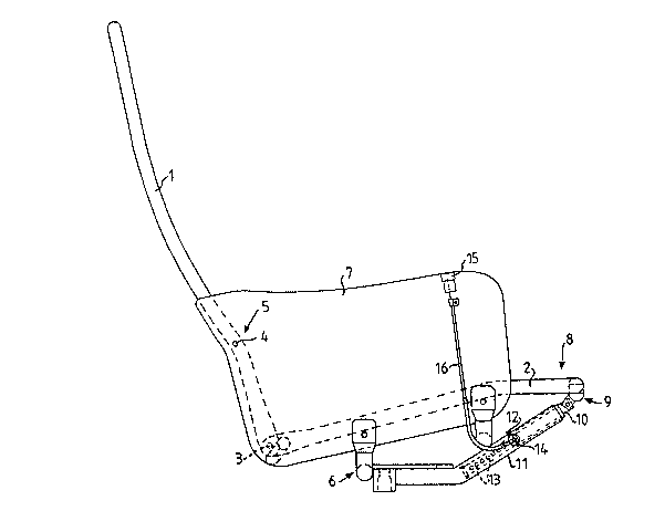
Fig. 1 is a schematic, partial side view of an ad;ustable
seat in accordance with a preferred embodiment of
the present invsntion,
Fig. 2 is a schematic, partial end view of the seat
illustrated in Fig. 1,
Fig. 3 is a schematic, partial side view, partly in cross
section, of the seat locking device without locking
pin,
Fig. 3A is a side view of a locking pin belonging to the
locking device illustrated in Fig. 3 and
Fig. 3B iS a side view of the locking pin illustrated in
Fig. 3A turned 9O.
As will be seen from the drawings, a preferred embodiment of
an adjustable seat in accordance with the present invention
comprises a back support 1 and a seat part 2 connected
pivotably to the support via a joint 3, both these chief
parts being carried by a substructure or frame 6. Via joints
4 the back support is pivotably attached to the rear edge
portions 5 of arm rests 7 included in the substructure 6. The
front portion 8 of the seat part 2 is pivotably attached to
the substructure 6 at least one pivoting point 9 on the
underside of the seat part 2 via a slide bar lO. The slide
bar 10 extends in the longitudinal direction of the seat part
2, towards the back support 1 and is in lockable coaction
with a fixed locking sleeve 11 pro~ecting from the lower part
of the substructure 6. The bar lO enables an angular setting
of the back support 1 relative the seat part 2 by its tele-
scopic coaction with, and displaceable location in, the
locking sleeve 11, in which the bar is fixable in at least
two predetermined, distinct locking positions. This is
achieved by a locking pin 14, which can be inserted via a
hole 12 in the surface of the sleeve 11 into a bore 13 in the
bar 10 for positionally fixing the bar in relation to the
sleeve 11 when the bore 13 is in register with the hole 12.
The pin 14 is spring biassed towards the bar lO in the sleeve

13010~3
l:L, and is operable from an operating means 15 on one of the
arm rests 7, with the aid of a Bowden cable 16. The fixed
locking sleeve 11 projecting from the substructure preferably
forms an angle to the horizontal plane attaining to
approximately 30. The free end of the locking pin 14 is
tapered 17 to facilitate its entry into one of the bores 13
disposed one after the other in the bar 10. The locking pin
and its hole 12 in the sleeve 11 are preferably disposed in a
region, at the middle of the sleeve 11, to provide the
greatest stability. The sleeve 11 is provided with a plastics
bushing 18 for reducing friction between sleeve and bar. The
number of bores 13 in the bar 10 for coaction with the
locking pin 14 is suitably 8-12 bores, which give just as
many adjusting positions of the seat.
By placing the pivoting joints 4 on the back suport 1 low
down in relation to the pivoting point 9 for the attachment
of the slide bar 10 to the front portion of the seat part 2,
there is achieved very balanced suspension of the back
support 1 and seat part 2 in the substructure 6. There is
then obtained a mechanical advantage with a lever action
which gives very little resistance when adjusting the seat
into a desired position.
. ~

Representative Drawing
A single figure which represents the drawing illustrating the invention.
Administrative Status

2024-08-01:As part of the Next Generation Patents (NGP) transition, the Canadian Patents Database (CPD) now contains a more detailed Event History, which replicates the Event Log of our new back-office solution.

Please note that "Inactive:" events refers to events no longer in use in our new back-office solution.

For a clearer understanding of the status of the application/patent presented on this page, the site Disclaimer , as well as the definitions for Patent , Event History , Maintenance Fee  and Payment History  should be consulted.

Event History

Description Date
Time Limit for Reversal Expired 2008-05-20
Letter Sent 2007-05-22
Grant by Issuance 1992-05-19

Abandonment History

There is no abandonment history.

Fee History

Fee Type Anniversary Year Due Date Paid Date
MF (category 1, 6th anniv.) - standard 1998-05-19 1998-05-13
MF (category 1, 7th anniv.) - standard 1999-05-19 1999-04-26
MF (category 1, 8th anniv.) - standard 2000-05-19 2000-05-12
MF (category 1, 9th anniv.) - standard 2001-05-22 2001-05-10
MF (category 1, 10th anniv.) - standard 2002-05-21 2002-05-06
MF (category 1, 11th anniv.) - standard 2003-05-20 2003-05-09
MF (category 1, 12th anniv.) - standard 2004-05-19 2004-05-07
MF (category 1, 13th anniv.) - standard 2005-05-19 2005-04-26
MF (category 1, 14th anniv.) - standard 2006-05-19 2006-05-09
Owners on Record

Note: Records showing the ownership history in alphabetical order.

Current Owners on Record
MOBELTEAM AB
Past Owners on Record
AKE LINDEN
ROGER GUSTAFSSON
Past Owners that do not appear in the "Owners on Record" listing will appear in other documentation within the application.
Documents

To view selected files, please enter reCAPTCHA code :


To view images, click a link in the Document Description column. To download the documents, select one or more checkboxes in the first column and then click the "Download Selected in PDF format (Zip Archive)" or the "Download Selected as Single PDF" button.

List of published and non-published patent-specific documents on the CPD .

If you have any difficulty accessing content, you can call the Client Service Centre at 1-866-997-1936 or send them an e-mail at CIPO Client Service Centre.


Document
Description 
Date
(yyyy-mm-dd) 
Number of pages   Size of Image (KB) 
Abstract 1993-10-30 1 28
Cover Page 1993-10-30 1 11
Claims 1993-10-30 3 65
Drawings 1993-10-30 3 32
Representative Drawing 2003-03-19 1 9
Descriptions 1993-10-30 5 175
Maintenance Fee Notice 2007-07-03 1 173
Fees 1997-05-05 1 64
Fees 1996-05-13 1 43
Fees 1994-05-09 1 31
Fees 1995-05-16 1 40