Language selection

Search

Patent 1301280 Summary

Third-party information liability

Some of the information on this Web page has been provided by external sources. The Government of Canada is not responsible for the accuracy, reliability or currency of the information supplied by external sources. Users wishing to rely upon this information should consult directly with the source of the information. Content provided by external sources is not subject to official languages, privacy and accessibility requirements.

Claims and Abstract availability

Any discrepancies in the text and image of the Claims and Abstract are due to differing posting times. Text of the Claims and Abstract are posted:

  • At the time the application is open to public inspection;
  • At the time of issue of the patent (grant).
(12) Patent: (11) CA 1301280
(21) Application Number: 1301280
(54) English Title: INDUCTIVE SENSING
(54) French Title: DETECTEUR INDUCTIF
Status: Expired and beyond the Period of Reversal
Bibliographic Data
(51) International Patent Classification (IPC):
  • G01D 05/14 (2006.01)
  • B26B 19/24 (2006.01)
  • G01D 05/20 (2006.01)
(72) Inventors :
  • BARANSKI, JAN (Australia)
(73) Owners :
  • UNIVERSITY OF WESTERN AUSTRALIA (THE)
(71) Applicants :
  • UNIVERSITY OF WESTERN AUSTRALIA (THE) (Australia)
(74) Agent: OYEN WIGGS GREEN & MUTALA LLP
(74) Associate agent:
(45) Issued: 1992-05-19
(22) Filed Date: 1987-09-29
Availability of licence: N/A
Dedicated to the Public: N/A
(25) Language of filing: English

Patent Cooperation Treaty (PCT): No

(30) Application Priority Data:
Application No. Country/Territory Date
PH8260 (Australia) 1986-09-29

Abstracts

English Abstract


ABSTRACT
An inductive sensing arrangement enables the distance of the
cutting head of an automated sheep shearing apparatus from
the skin of a sheep to be determined. Sensors on the
cutting head include a coil, the inductance of which varies
in accordance with the distance of the coil from a
conductive surface such as the skin of a sheep. An output
voltage represents the distance of the coil from the
conductive surface.
870928,!jcspe.006,uwausa.spe,


Claims

Note: Claims are shown in the official language in which they were submitted.


CLAIMS
1. Apparatus for measuring the proximity of an object to
a surface of low conductivity material, comprising at least one
sensor located on said object, said sensor including a single
turn coil connected in a tuned circuit, the inductance of said
coil varying in accordance with changes in said proximity, and
RF means coupled to said tuned circuit for applying a UHF RF
signal with a frequency of about 830 MH2 to said tuned circuit,
and for detecting at the output of said tuned circuit a voltage
amplitude representing said proximity.
2. Apparatus according to claim 1 wherein said coil is
connected in series with a capacitor trimmer.
3. Apparatus according to claim 1, further including a
pair of sensors oriented in side-by-side relationship.
4. Apparatus according to claim 3 wherein said sensors are
incorporated into a cutter head of a sheep shearing device, and
wherein said surface comprises the skin of the sheep.
5. A method for measuring the proximity of an object to
a surface comprising:
(a) providing at least one single turn coil in a tuned
circuit having a predetermined shape for inducing
an eddy current flow path in said surface, said
eddy current flow path mirroring said predeter-
mined coil shape;
(b) detecting changes in the inductance of said coil
as said proximity varies, including the steps of
applying a UHF RF frequency signal of about 830
MHz across said tuned circuit and sensing voltage
across said tuned circuit; and
(c) representing proximity of said coil with said
surface in response to said sensed voltage.
-6-

6. A method according to claim 5 wherein the change in
inductance .DELTA.L is determined by the following equation:
.DELTA.L = <IMG> <IMG> - M
where µ is the permeability of the surface; ? is the conductivity
of the surface; .delta. is the depth of penetration of the eddy current
in the surface; M is the mutual inductance; and h is the distance
between the surface and a centre of the eddy current coil.
7. An automated sheep shearing apparatus including:
a cutter head;
an inductive sensing arrangement including a sensor
package located on said cutter head, said package including a
pair of sensors, each of said sensors including a single turn
coil connected in series with a capacitance trimmer to form a
tuned circuit;
means coupled to said sensors for applying a UHF RF signal
of about 830 MHz to each said coil; and
means coupled to said sensors for detecting voltage changes
across each said tuned circuit and for determining the distance
between the cutter head and the skin of the sheep in response to
said detected voltage changes.
8. The automated sheep shearing apparatus as defined in
claim 7 wherein said means for detecting voltage changes includes
means for amplifying each of said sensor generated signals and
data acquisition means for receiving and acquiring said amplified
signals.
9. Apparatus as in claim 1 wherein:
said coil comprises a planar coil;
said tuned circuit further comprises a trimmer
capacitance connected in series with said coil to form a resonant
circuit;
-7-

said RF means includes radio frequency generating means
coupled to said tuned circuit for generating said UHF RF signal
in the form of an alternating current signal and for applying
said alternating current signal to said tuned circuit; and
said coil discriminates between wool and sheep skin in
proximity to said coil.
10. A method as in claim 5 wherein:
said single turn coil comprises providing a planar coil
connected in series with a trimmer capacitance to form a series
resonant circuit; and
said method further includes
applying said UHF signal to said series resonant
circuit and discriminating between wool and sheep skin in
proximity to said coil.
11. Apparatus as in claim 7 wherein:
each said coil comprises a planar coil; and
said means coupled to said sensors for applying UHF RF
signal to each coil includes radio frequency generating means
coupled to said sensors for generating said UHF signal and for
applying said alternating current signal to said sensors; and
said coil discriminates between wool and sheep skin in
proximity to said coil.
12. Apparatus according to claim 11 wherein each said coil
is printed on a printed circuit board each said coil and trimmer
capacitor together form a series resonant tuned circuit resonat-
ing at the frequency of said UHF signal and said generated UHF
signal corresponds to the resonant frequency of said tuned
circuit, proximity between said coils and said sheep skin
changing the inductance of said coils and thereby detuning said
tuned circuit from said resonant frequency.
13. Apparatus according to claim 12 wherein said coils
induce eddy current to flow through said sheep skin in a path
-8-

mirroring the shape of the coils and said eddy current flow
changes the inductance of said coils.
14. Apparatus according to claim 13 wherein said inductance
change is dependent upon the mutual inductance between said eddy
current paths and said coils.
15. Apparatus according to claim 14 further including a
ground plane conductive surface disposed on another surface of
said printed circuit board.
16. Apparatus according to claim 15 further including a
radial Faraday shield operatively coupled to said coil.
-9-

Description

Note: Descriptions are shown in the official language in which they were submitted.


3~
2 INDU~TIYE 8EN~3ING
3 BACKGROUND OF THE INVENTION
4 Field of the Invention
This invention relates to remote sensing, and in particular
6 relates to proximity sensing in automatically controlled
7 operations, for example in sensing the position of a shearing
8 head, in relation to the skin of a sheep, in an automated sheep
g shearing system.
Description of the Prior Art
11 Capacitance proximity sensing in automated sheep shearing
12 systems, and the use of resistant proximity sensing in such
13 systems, have been described in Australia. The capacitative
14 sensing means includes exposed electrode means defining with a
body to be sensed a variable capacitance, a fixed-value capaci-
16 tance, and a voltage source connected to the fixed-value and
17 variable capacitances to define a capacitative voltage divider,
18 and means for detecting the voltage across one arm of said
19 divider.
BRIEF SUMMARY OF THE INVENTION
21 The invention pertains to an apparatus for measuring the
22 proximity of an object to a surface of low conductivity material.
23 The object may comprise at least one sensor located on it and the
24 said sensor may include a single turn coil connected in a tuned
circuit. The inductance of said coil can be varied in accordance
26 with changes in said proximity. RF means can be coupled to said
27 tuned circuit for applying a UHF RF signal with a frequency of
28 about 830 MHz to said tuned circuit, and for detecting at the
29 output of said tuned circuit a voltage amplitude representing
said proximity.
31 The invention also provides an arrangement according to the
32 preceding paragraph, characterized in that the distance of said
33 surface is represented by a voltage across the said tuned
34 circuit.
The invention further provides a method of determining the
36 proximity of a surface, including the steps of detecting the
37 change in inductance which results from a change in proximity,
38 and processing information representing said
`~
~,.. .

~3~ 8~
1 inductance change to provide a representation of the
2 dis~ance from the said surface.
3 Preferably, said arrangemen~ includes a coil capable of
4 generating a magnetic field, and said means operates to
determine the inductance change of said coil resulting from
6 the induction of an eddy current coil in the material of
7 said element.
8 BRIEF DESCRIPTION OF THE DRAWINGS
9 Figure 1 is a diagram relating to the theoretical basis
of the invention;
11 Figure 2 is a block diagram of one embodiment of a two-
12 sensor inductance sensor arrangement according to the
13 invention;
14 Figure 3 is a more detailed diagram of one sensor
channel of the arrangement of Figure 3; and
16 Figure 4 is a graph of VOuT plotted against l/h.
17 DETAILED DESCRIPTION OF THE PREFERRED EMBODIMENT
18 The inductive sensor of the present invention uti1izes
19 the eddy currents phenomenon. When a magnetic field is
produced in the vicinity of a material characterized by
21 conductivit~ y and permeability ~ part of this field
22 penetrates into the material to the conventional depth of
23
24 ~ ~ (1)
26 The field induces eddy currents in the material, which have
27 circular paths parallel to the material surface 10~ If the
28 source of the magnetic field and in turn the eddy currents
29 is a coil 12, these currents will change the inductance of
870928,~jcspe.006,uwausa.spe.

1 the coil 12. Assuming that the coil is of a single
2 circular loop made from a wire of small section and the
3 surface conductivity is high, the exciting coil 12 will
4 induce an effective eddy current coil 14 of the shape shown
S in Figure 1, mirroring the shape of exciting coil 12. The
6 mutual inductance of the two coils is mathematically
7 described as :
10 M = K ~ 2 ) J(k) - K(k)] (2)
11
12 where : K = r2 ~ ; J (k) and K(k) - elliptic integrals of
first and second order~r,d,h as in Fig. 1.
14
A complete description of the inductance change is only possible
16 for small distances (h r)
17
18 ~ = ~r~ [ah]~ M
19
21
22 Turning now to Figures 2 to 4, the sensor package 16
23 consists of two sensors placed side by side, designated
24 functionally 'left' (L) and 'right' (R), which are part of
the inductance sensing system shown on Figure 2. The
26 package was designed to fit the cutter head of a sheep
27 shearing robot. It is suggested that a third, 'back',
28 sensor could be added and that the system could he
29

~3~ 8V
1 integrated by including the power splitter 18 and detec~ors
2 (20, 22) in the sensor package 16.
3 A frequency control unit 24 feeds into a radio
4 frequency plug-in unit 26, preferably at HP 86220A.* Radio
frequency amplifier 28 (preferably involving mini-circuits
6 ~HL-2-12) feeds to power splitter 18 (preferably MCL ZFSC-4-
7 1, which in turn feeds to the sensor package.
8 Detectors 20, 22 for right and left sensors R and L
9 respectively have their signals amplified by amplifiers 30,
32 respectively, which produces V0uT for each sensor, for
11 supply to a data acquisition system 34
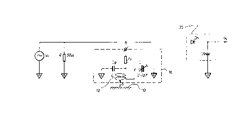
12 Figure 3 shows a single sensor channel where Ui is the
13 powering signal, R is the characteristic impedance of the
14 splitter 18, and Dl and CD form a RF detector 20. In the
sensor package there is a single turn coil 12, printed on
16 double-sided copper-clad epoxy glass board (not shown) which
17 is connected in series with a capacitance trimmer C to form
18 a tuned circuit, Cp representing a parasitic capacitance.
19 parallel arrangement of the circuit is also possible,
although in such an arrangement the influence of the
21 parasitic capacitance is much bigger.
22 The other side of the board is grounded and there is a
23 radial Faraday shield in front of each sensor.
24 The self inductance of the single turn coil 12 iq
affected by the ground plane according to equation (3) as
26 used for proximity measurement, so the resonant frequency
27 had to be found experimentally. It i8 desirable to use a
28 high operating frequency to decrease the depth of
29 penetration (~) and increase the change of inductance; one
*Trade-mark

1301Z80
1 frequency used in experiments was in the vicinity of 830
2 MHz~
3 When the sensor approaches a conductive material 10 the
4 value of inductance L decreases, the circuit gets out of
tune, which changes the voltage across the circuit. In
6 experiments, the measured change of Vs was approximately
7 1.5V over a distance of 60mm.
8 Figure 4 shows characteristics of the sensor measured
9 on the outputs (V0uT) of the amplifiers 30, 32.
The nature of fleece, especially near the skin 10, of a
11 sheep, suggests an electrical anisotropy. When the surface
12 conductivity is considered, the weakest properties are found
13 on any plane locally parallel with the skin. Such a
14 position naturally corresponds with a normal cutter position
during sheep shearing. The inductive sensor discriminates
16 between the surface conductivity of the sheep's skin and
17 the wool surface conductivity. This significantly
18 decreases sensitivity to the wool conditions.
19 The sensor of this invention can be tuned to different
working points on the resonant characteristic and to
21 different resonant frequencies. A 'band sensitivity' can
22 be obtained to detect materials only from a certain range of
23 conductivity and permeability. The inductive sensor can
24 also be employed directly for conductivity and permeability
measurement.
870928,1jcspe.006,uwausa.spe,

Representative Drawing
A single figure which represents the drawing illustrating the invention.
Administrative Status

2024-08-01:As part of the Next Generation Patents (NGP) transition, the Canadian Patents Database (CPD) now contains a more detailed Event History, which replicates the Event Log of our new back-office solution.

Please note that "Inactive:" events refers to events no longer in use in our new back-office solution.

For a clearer understanding of the status of the application/patent presented on this page, the site Disclaimer , as well as the definitions for Patent , Event History , Maintenance Fee  and Payment History  should be consulted.

Event History

Description Date
Inactive: IPC from MCD 2006-03-11
Inactive: Adhoc Request Documented 1996-05-19
Time Limit for Reversal Expired 1995-11-20
Letter Sent 1995-05-19
Grant by Issuance 1992-05-19

Abandonment History

There is no abandonment history.

Owners on Record

Note: Records showing the ownership history in alphabetical order.

Current Owners on Record
UNIVERSITY OF WESTERN AUSTRALIA (THE)
Past Owners on Record
JAN BARANSKI
Past Owners that do not appear in the "Owners on Record" listing will appear in other documentation within the application.
Documents

To view selected files, please enter reCAPTCHA code :


To view images, click a link in the Document Description column. To download the documents, select one or more checkboxes in the first column and then click the "Download Selected in PDF format (Zip Archive)" or the "Download Selected as Single PDF" button.

List of published and non-published patent-specific documents on the CPD .

If you have any difficulty accessing content, you can call the Client Service Centre at 1-866-997-1936 or send them an e-mail at CIPO Client Service Centre.


Document
Description 
Date
(yyyy-mm-dd) 
Number of pages   Size of Image (KB) 
Claims 1993-10-29 4 128
Abstract 1993-10-29 1 10
Drawings 1993-10-29 4 38
Representative Drawing 2003-03-18 1 4
Descriptions 1993-10-29 5 153
Fees 1994-03-24 1 32