Note: Descriptions are shown in the official language in which they were submitted.
1301480
The invention concerns a device to test the permeability
to air of two-dimensional articles, called "test object" in what
follows, in particular of felts and screens used in machines and
installations for manufacturing paper.
A device of this type is known from EP Patent 0 096 31.
This device is designed as a movable instrument whose measuring
channel is separated into two coaxial channel sections that define
between each other a measuring aperture. The test object, for
instance, a sheet made of a fabric, a screen, or a felt, has to be
inserted into the measuring aperture and, subsequently, must be
clamped tight.
The device is a technically complex construction which
must be attached to a multitude of positions on the test object in
order to arrive at permeability profiles, a procedure that takes a
correspondingly long time. The test object must be clamped tight
in order to obtain as uniform an air flow through the test object
as possible and to avoid significant losses through leakage. By
basing the design on a belt channel with equal pressure it is
further possible to avoid most leakage losses that are caused by
the surface structure of the test objects.
The purpose of the invention is to present a test device
for finding the permeability to air at different areas of a test
object, rapidly and in a simple fashion, combined with the
advantages of encompassing a wide range of values, covering at
least a ratio of 50, and a high accuracy. The test device is
supposed to be usable with ease and without problems, it should be
appropriate for a large variety of objects of different
permeability, and it should be locally movable in order to allow
for the acquisition of different permeability profiles. Finally,
-- 1 --
~$
1 3f~1 ~80
the device should be applicable even in the case of slowly moving
test objects.
Thus, the invention provides a test device for testing
the air permeability of a substantially two-dimensional article,
the device for testing the air permeability of an article, and
particularly felts and screens associated with the manufacture of
paper products, the device being of the type including a measuring
channel through which air is propelled through utilization of a
blower mechanism, and including measuring means for measuring the
flow rate of air within the measuring channel, the air being
propelled through a measuring area of the exposed surface of the
article as a function of a controlled constant pressure difference
created at the adjacent measuring area, the device further being
of the type including a longitudinal positioned belt channel
juxtaposed about the measuring channel in which the belt channel
is additionally and operably directing propelled air from the
blower mechanism, wherein the measuring channel and the belt
channel each further include an orifice immediately adjacent to the
exposed surface of the article, the improvement in the air
permeability testing device further comprising: the blower
mechanism, the measuring channel, the measuring means for
determining the rate of air flow in the measuring channel, the
measuring area and the belt channel being integrated into a single
operational testing device capable of being placed for air
permeability testing to one of either of two sides of the article
being tested: the measuring means comprising a fan wheel anemometer
having a fan wheel element operably positioned within the measuring
channel for direct exposure to the air being propelled therein:
the measuring channel containing the fan wheel anemometer wheel
- 2 -
~3~1~80
element being operably connected to the orifice of the measuring
channel immediately adjacent to the article through a channel
section element, immediately adjacent the measuring channel orifice
having a substantially cylindrical longitudinal construction, with
the channel section further and operably being attached to a
tapered longitudinal section emanating towards the measuring means
in order to insure that the propelled air stream is unidirectional;
the air permeability testing device further including in at least
one position upstream from the fan wheel element of the fan wheel
1~ anemometer, flow rectifier means for precluding the creation of
rotational flows of propelled air onto the surface of the fan wheel
element; the substantially cylindrical longitudinal section
immediately adjacent the measuring channel area having one or more
sensing means operably associated therein for measuring the extent
of static pressure created at the area of measuring channel, for
the purpose of regulating the rotational speed of the blower
mechanism so as to maintain a desired static pressure value; one or
more of the belt channel and the measuring channel means being of
such a geometric configuration so as to equalize the propelled air
flow volume and velocity longitudinally conducted through the belt
channel to the propelled air flow volume and velocity
longitudinally directed through the measuring channel.
The device as described in the invention allows to
measure air permeabilities without the ~equirement to clamp the
test object between the segments of the channel in which the air
flow is measured. Instead, the invention makes it possible to
attach channel segments to one side of the test object only, a
procedure that has the advantage that the device can be used for
test objects which are only accessible from one side and/or which
move continuously.
.~ - 3 -
~3~1~80
The test device can be constructed in such a fashion that
it has a low weight and can be used manually with ease. This
feature has the advantage that the test device allows for
continuous measurements while it is being moved relative to a test
object that itself is in motion. As a consequence, longitudinal
and transverse measurements can be made.
In the process, the pressure drop in the case of diverse
fabric permeabilities is automatically set to a predetermined value
and kept at this mark. The replica of the natural flow through the
test object, due to the screening of the flow in the measuring
channel by the test object, by the air flow in the belt channel has
the advantage to protect the air flow in the measuring channel from
exterior influences and to make available an unavoidable amount of
leakage air.
Thus, the test device permits the determination of air
permeabilities for felts, screens, fabrics, and similar sheets in
a short time. The permeability properties have a significant
influence on various operating conditions of machines that are run
with such felts or screens.
Favourable designs of the invention are the subject of
characteristics of secondary claims.
A prefered version of the test device according to the
invention is shown in the diagrams:
FIGURE 1 shows a longitudinal cross-section of the test
device;
FIGURE 2, on a magnified scale, shows the section of
FIGURE 1 that is marked by the dash-dotted circle;
FIGURE 3 shows the section as in FIGURE 2 for an
alternative version of the design.
`` - 4 -
13~}1480
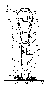
The design of the test device is for a hand-held
instrument. The device may obviously also be used as an instrument
to be incorporated into a production machine, delivering air
permeability profiles for a fabric sheet that is being tested. The
device has a measuring tube which was given, as a unit, the
designation (10). A fan attachment (12) is attached on this tube
(10). The measuring tube (10) comprises a cylindrical casing (14)
that forms, together with a coaxially inserted casing inset (16),
a belt channel (18) and defines an interior measuring channel (20).
Whereas the belt channel (18) forms a space that, in
segments, is of a cylindrical formds, the measuring channel (20)
contains only a lower cylindrical channel segment (22), at least 20
mm long, whose interior circumference defines a measuring spot, for
instance, on a fabric sheet (24) in a machine for manufacturing
paper. The air permeability of the fabric sheet (24) is measured
over the area of this measuring spot.
The cylindrical channel segment (22) turns into the
channel segment (26) that is tapered upwards in the form of a cone.
The angular aperture of the tapered section (26), measured from
wall to wall, is at most 18, and preferably between 10 and 15.
The fan wheel (28) of a fan-wheel anemometer (30) is placed into an
adjacent channel segment (29).
Adjacent to the channel segment (29), there is a channel
segment (32) that is flared by a small amount in the upward
direction and in the form of a cone.
The lower cylindrical channel segment (22) of the
measuring channel (20) has preferably a diameter of 35 mm. In this
case, the resulting measuring spot has an optimal size for rating
the test object. The channel segment (26), above segment (22),
- 5 -
:
"
1301480
shows a diameter that preferably decreases down to a value of 18.2
mm. The ratio 35 mm to 18.2 mm of the diameters results in optimum
conditions for a wide measuring range, if the sensitivity of, and
the maximum flo~ velocity for, the fan-wheel anemometer (30) are
taken into account, in particular, in the cases where dense felts
and open dry screens form the test objects. Apart from the
optimum, a suitable range for the ratio of these diameters is
between 1.2 and 3.5, and preferably between 1.8. and 2Ø
The fan-wheel anemometer probe (30) is run radially
outwards; in order to prevent flow separation inside the belt
channel (18) when the air stream flows around the fan-wheel
anemometer, a casing (33) is designed for the anemometer in the
belt channel (18) that is designed for optimum flow
characteristics. The air flow through the belt channel (18) must
be equally distributed. To achieve this, a similar counterpart is
provided at a position diametrically across from the casing (33).
This counterpart is not shown in the diagram.
The design contains, for the same reason, two additional
casings in the belt channel (18) that are offset by 90 and serve
as air-conducting elements.
A recording head (34) is put on the tube casing (14) into
which the casing inset (16) enters with its upper end (16'). The
recording head (34) is tapered in the upward direction in this
area. A cylindrical segment joins the tapered segment and forms a
mounting collar (36). The fan mount (12) is placed on this collar
(36). The fan mount (12) contains in the upper portion a radial
blower (38) in an air conduction chamber (40), the air conduction
chamber being formed by the hood (42) put on the fan mount (12).
The radial blower (38) contains a driving motor (44) which may be
~3Q1480
either a regulated DC motor or a synchronous AC motor. The motor
is supported by a support ring (46) that is coaxial to the inner
channel (20). The support ring (46) is supported by a flow
rectifier (48) that may, for instance, be formed by a honeycomb
lattice. A radial fan wheel (50), positioned above the flow
rectifier (48), sits on the shaft of the driving motor (44). The
fan wheel (50) sucks air through a central inlet (52) in the hood
(42) and pushes it through the flow rectifier (48). Ad~acent to
the rectifier (48) is an inset (54) that is tapered in the form of
a cone in the downward direction and whose end piece (54') is
cylindrical and sticks into the collar (36). An additional flow
rectifier (56), preferably formed by a honeycomb lattice, is placed
into the upper end of the inner channel (20). At least the segment
(56') is necessary for measuring procedures in order to guarantee
an irrotational flow in front of the fan wheel (28).
The casing inset (54) is radially surrounded by a portion
of the casing (58) that, too, is tapered in the downward direction
in the form of a cone. The ring-shaped end piece (58') of the
casing (58) is attached to the mounting collar (36). A cylindrical
handle piece (60) is formed between the head (34) and the portion
(58) of the casing.
The inset (54) forms an inner flow channel (62) with a
downwards tapered cross-section, whereas inset (54) and the portion
(58) of the casing form together the belt channel (64) that is
tapered in the downwards direction in the form of a cone. The belt
channel (64) is connected to the flow channel (62) by means of a
ring of connecting openings (66) in the upper portion of the inset
(54), positioned parallel to the axis. The air flow produced by
the radial fan (38) is aligned by the flow rectifier (48) in such
- 7 -
13(~480
a fashion that the flow is partitioned according to the flow cross-
sections in the cylindrical channel segment (22) and the belt
channel segment (18') that surrounds the channel segment (22). The
ratio of the flow cross-sections of the measuring channel (20) and
the belt channel (18) is essentially kept constant, at a preferred
value of 2.33, over the entire flow path from the cylindrical end
piece (54') of the inset (16) to the orifice of the channel. An
operable range for the ratio of the interior cross-section of the
orifice of the belt channel to the cross-section of the orifice of
said measuring channel is larger than 0.5 and preferably greater
than 1Ø In this manner it is guaranteed that the amount of air
flowing through the belt channel (18) suffices to protect the air
flowing through the measuring channel (20) against external
influences and to supply an unavoidable amount of leakage air.
It is desirable to equip the lower end of the measuring
channel (20), to be attached to the test object (24), as well as
the belt channel (18) in this area with a flow rectifier (68) which
improves the laminar character of the emerging air flow and the
efficiency of the pressure distribution for the purpose of radial
sealing. The wall thickness between measuring channel (20) and
belt channel (18) is preferably less than 2 mm and preferably 1 mm
in this area. In any case, it should be less than 5 mm in order to
guarantee the screening effect the belt-channel flow has on the
measuring-channel flow at the test object. This thickness should
be maintained for at least 10 mm from the ends of said channels.
As far as the arrangement for the portion of the flow
rectifier (68) which is to be located in the lower end of the belt
channel (18) is concerned, this portion, identified as (68') in
FIGURE 3, is preferably designed in such a fashion that it is
- 8
13Q1480
fastened, for instance, by means of an adhesive, to the interior
circumference of the channel wall segment (70) and is flush with
the lower face (71) of the channel wall segment (70). This
arrangement makes sure that the flow rectifier portion (68') always
rests on the fabric.
The lower edge of the measuring channel (20) projects
over the end piece of the cylindrical tube casing (14). As shown
in FIGURE 2, the lower end of the belt channel (18) is formed by an
axially sealing ring (70), equipped with springs, that sits on the
tube casing (14) with sufficient play to guarantee a perfect
attachment of the lower ring area of the sealing ring (70) on the
test object (24) even in the case of a tilt of the test device with
respect to the test object (24). In this manner it is ascertained
that attaching the test device with a tilt of a few degrees does
not lead to changes in the recordings, that is, to errors in the
measurements. In the case that the device is attached from below,
the sealing ring (70) is fixed by means of a ring-shaped stop (78)
which forms part of a support t80) that is fastened to the tube
casing (14) and used to support the pressure springs (82) acting on
the sèaling ring (70).
In order to obtain accurate test results it is important
to ascertain that around the edge of the measuring spot no
undefined amount of air is conducted above the test object instead
of through the test object. In addition, it is important that the
radial distance from the measuring channel (20) to the belt channel
(18) is preferably between 1 and 2 mm so that this lateral flow is
avoided.
The permeability of the test object (24) is measured with
the test device by creating a well-defined pressure drop of, for
_ g
~L3t~4~30
instance, 1 mbar or 1.27 mbar, between the upper and the lower side
of the test object in the area of the measuring spot. The amount
of air flowing per unit surface through the test object (24) at a
given pressure difference depends on the type of fabric, its
manufacture and dirtying, and the stretching of the test object.
For this reason, the air permeability may sometimes drastically
differ among measuring points. In our case, the pressure
difference is generated, by means of blowing, as excess pressure
with respect to the ambient pressure just above the test object
(24). The volume flow in the measuring channel (20) is then
measured and assigned to the free cross-section of the measuring
channel (20), that is, to the measuring spot. The measured value
may be considered an average over the actual measuring area.
While this description is based primarily on a device in
which the airstream is propelled toward the article being measured,
the invention is also operable by drawing said stream from said
article.
The static pressure difference that is generated in the
measuring channel (20) is continuously measured. For this purpose,
as shown in FIGURE 2, several boreholes (72) are designed along the
periphery of the lower cylindrical end piece (22) of the measuring
channel (20) that penetrate the wall of the casing (16) and
discharge into a collecting channel (74). The boreholes have
diameters of, preferably, 0.5 mm, but not more than 1 mm. The
collecting channel or ring (74) is connected, via the connecting
channel ~76), to an instrument, attached to the test device, which
measures the static pressure difference. This continuous
monitoring and controlling of the static air pressure in the
measuring channel (20) makes sure that, in the case where the belt
-- 10 --
1301480
channel (18) starts leaking, for instance, if the attachment of
the test device to the test object (24) had been done improperly,
the amount of air is increased automatically according to the
leakage, with the result that the air pressure in the area of the
belt channel (18) drops insignificantly. The output of the radial
blower (38) is correspondingly varied.
In summary, the test device works as follows:
The permeability to air of the test object (24) is
measured by attaching the test device to the test object. The air
flow, generated by the radial blower (38) and flowing through the
two channels (18) and (20), meets the test object (24) in the area
of the measuring spot and flows through the test object. In the
process, the air flow drives a fan-wheel anemometer (30) which
measures the flow rate. The test object (24) generates a pressure
drop that depends on its permeability and the air volume that flows
through per unit time and unit area. The pressure drop is held
constant, for instance, at 1 mbar by controlling the air flow rate.
THe resulting changes in this flow rate are then recorded by the
fan-wheel anemometer (30) for the purpose of analysis.
, -- 11 --
.
.
., .