Language selection

Search

Patent 1301728 Summary

Third-party information liability

Some of the information on this Web page has been provided by external sources. The Government of Canada is not responsible for the accuracy, reliability or currency of the information supplied by external sources. Users wishing to rely upon this information should consult directly with the source of the information. Content provided by external sources is not subject to official languages, privacy and accessibility requirements.

Claims and Abstract availability

Any discrepancies in the text and image of the Claims and Abstract are due to differing posting times. Text of the Claims and Abstract are posted:

  • At the time the application is open to public inspection;
  • At the time of issue of the patent (grant).
(12) Patent: (11) CA 1301728
(21) Application Number: 1301728
(54) English Title: BROODER LAMP
(54) French Title: LAMPE D'ELEVOIR
Status: Expired and beyond the Period of Reversal
Bibliographic Data
(51) International Patent Classification (IPC):
  • F21V 15/00 (2015.01)
  • A01K 31/20 (2006.01)
  • H05B 01/00 (2006.01)
(72) Inventors :
  • MAENDEL, BENJAMIN (Canada)
(73) Owners :
  • BAKER COLONY FARMS LTD.
(71) Applicants :
  • BAKER COLONY FARMS LTD. (Canada)
(74) Agent: ADE & COMPANY
(74) Associate agent:
(45) Issued: 1992-05-26
(22) Filed Date: 1988-07-12
Availability of licence: N/A
Dedicated to the Public: N/A
(25) Language of filing: English

Patent Cooperation Treaty (PCT): No

(30) Application Priority Data: None

Abstracts

English Abstract


- 7 -
BROODER LAMP
ABSTRACT OF THE DISCLOSURE
A brooder lamp for small animals, especially
pigs, has a stainless steel reflector housing a bulb
socket and a resilient metal plate extending across the
reflector, in front of the socket. An opening in the
plate is sized to pass the narrow neck of the bulb but to
engage the widening port and to bias it away from the
socket. This provides a secure mounting for the bulb in
the socket to inhibit damage due to impact with the lamp
of playful animals.


Claims

Note: Claims are shown in the official language in which they were submitted.

- 6 -
CLAIMS
1. In a brooder lamp comprising a reflector
housing and a bulb socket secured to the housing for
receiving a heat lamp bulb base, a resilient metal plate
secured to the housing and extending across the socket,
the plate having an opening therein aligned with the
socket, the opening being so sized and the metal plate
being so positioned that with the base of the bulb
inserted through the opening and engaged with the socket,
the metal plate is engaged with the bulb and is
resiliently deflected towards the socket.
2. The brooder lamp according to Claim 1 wherein
the reflector housing is rectangular.
3. A brooder lamp according to Claim 2 wherein the
metal plate is secured to one side of the housing and
extends therefrom across the socket.
4. A brooder lamp according to Claim 1 wherein the
reflector housing is polished steel.

Description

Note: Descriptions are shown in the official language in which they were submitted.


~3~728
BROODER LAMP
FIELD OF THE INVENTION
This invention relates to a brooder lamp for
use with young animals, for ex~mple chickens or pigs, to
ensure that the animals are kept at the required elevated
temperatures.
BACKGROUND OF THE INVENTION
Brooder lamps are usually suspended above a pen
or the like to keep young animals at required elevated
temperatures. Generally such brooder lamps comprise a
spun aluminum reflector bowl which surrounds and protects
a heat bulb. In addition, a metal grid extends across
- the open end of the bowl to prevent any damaged bulb from
falling onto the animals below and to reduce the access
by the animals to the hulb.
However one problem arises in devices of this
type in that particularly with pigs they spend a signifi-
cant part of their day attempting to play with the
brooder lamps and can cause damage to the lamp. The life
of the expensive bulb is significantly reduced in that
the glass envelope of the bulb often works loose from the
metal base thus breaking the bulb and terminating its
~ life.
.. ~

SUMMARY OF THE INVENTION
The present invention is concerned with
improvements in a lamp of thls general t~pe.
According to the present invention there is
provided a brooder lamp comprising a reflector housing
and a bulb socket secured to the housing for receiving a
heat lamp bulb base, a resilient metal plate secured to
the housing and extending across the socket, the plate
having an opening therein aligned with the socket, the
opening being so sized and the metal plate being so
positioned that with the base of the bulb inserted
through the opening and engaged with the socket, the
metal plate is engaged with the bulb and is resiliently
deflected towards the socket.
The metal sheet presses against the widening
part of the bulb to hold it away from the socket and to
reduce the possibility of side to side movement relative
to the socket and the bulb's base.
Preferably the housing is of a rectangular
shape and is formed from stainless steel rather than
aluminum to increase the reflection of the surfaces.
This increased reflection tends to reduce the temperature
of the metal surfaces and thus reduce the danger of
overheating of the bulb which again can lead to shortened

life.
BRIEF DESCRIPTION OF THE DRAWINGS
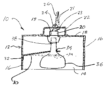
Figure 1 is a sectional elevational of a lamp
according to the present invention; and
Figure 2 is an isometric view of the lamp of
Figure 1.
DETAILED DESCRIPTION
Referring to the drawings there is illustrated
a brooder lamp 10 consisting of a reflector housing 12 of
polished stainless steel. The housing is generally rec-
tangular in form with longer sides 14 that converge from
the open bottom to the top of the housing and two trape-
zoidal ends 16. The top 18 of the reflector housing has
an opening 19 therein to receive a ceramic bulb socket
20. The socket 20 is of conventional form and is secured
to the top of the reflector housing in the conventional
way. The end of the socket projecting above the housing
is enclosed in a socket housing 22 which is itself
secured to the top 18 of the reflector housing. A lug 24
projects from the top of the socket housing 22 and is
secured to a chain 26 which serves to suspend the lamp
10. The electrical leads 21 from the ceramic socket 20
pass through an opening 23 in the socket housing 22 and
extend along the suspension chain 26. Four vent holes 28

are formed in the sides of the socket housi.ng 22 to
eliminate any excessive heat buildup within the socket
housing.
A resilient metal plate 30 is located within
the reflector housing 12. A flange 32 along one edge of
the plate is secured to one end 16 of the housing, while
the main body of the plate projects into the housing,
across the socket 20. The plate has an opening 34 formed
in it, in alignment with the socket 20 so that in moun-
ting a bulb 36 to the socket 20, the bulb base 38 is
inserted through the opening 34 and then screwed into the
socket 20. The opening 34 is so sized that it will
accept the narrow neck of the glass envelope of the bulb
36 but will not pass the widenin~ end. The plate 30 is
so located relative to the socket 20 that when the bulb
is inserted through the opening 34 in the plate and its
base 38 screwed into the ceramic socket 20, the plate
engages the widening part of the bulb and deflects
resilientl~ from the broken line position illustrated in
Figure 1 to the solid line position shown in that figure.
The result is that there is a resilient bias on the bulb
in a downward direction, centering the bulb in the
opening 34 to inhibit side to side movement of the bulb,
which tends to break the glass envelope of the bulb from

~3~28
its base 38. The biasing force also provides a greaterfrictional engagement between the bulb base and the
socket in addition to the frictional engagement of the
bulb envelope with the plate 30. This inhibits loosening
of the bulb base 38 in its socket ~0 due to vibration.
The illustrated lamp is completed by a wire
grid (not shown) mounted on the bottom end ~o prevent the
animals under the lamp from coming into direct contact
with the bulb.
While one embodiment of the present invention
has been described in the foregoing, it is to be under-
stood that other embodiments are possible within the
scope of the present invention. It is intended that the
scope of the present invention be ascertained solely by
reference to the appended claims.

Representative Drawing
A single figure which represents the drawing illustrating the invention.
Administrative Status

2024-08-01:As part of the Next Generation Patents (NGP) transition, the Canadian Patents Database (CPD) now contains a more detailed Event History, which replicates the Event Log of our new back-office solution.

Please note that "Inactive:" events refers to events no longer in use in our new back-office solution.

For a clearer understanding of the status of the application/patent presented on this page, the site Disclaimer , as well as the definitions for Patent , Event History , Maintenance Fee  and Payment History  should be consulted.

Event History

Description Date
Inactive: IPC deactivated 2015-03-14
Inactive: IPC from PCS 2015-01-17
Inactive: First IPC from PCS 2015-01-17
Inactive: IPC expired 2015-01-01
Inactive: First IPC assigned 2014-10-29
Time Limit for Reversal Expired 1998-05-26
Letter Sent 1997-05-26
Grant by Issuance 1992-05-26

Abandonment History

There is no abandonment history.

Owners on Record

Note: Records showing the ownership history in alphabetical order.

Current Owners on Record
BAKER COLONY FARMS LTD.
Past Owners on Record
BENJAMIN MAENDEL
Past Owners that do not appear in the "Owners on Record" listing will appear in other documentation within the application.
Documents

To view selected files, please enter reCAPTCHA code :


To view images, click a link in the Document Description column. To download the documents, select one or more checkboxes in the first column and then click the "Download Selected in PDF format (Zip Archive)" or the "Download Selected as Single PDF" button.

List of published and non-published patent-specific documents on the CPD .

If you have any difficulty accessing content, you can call the Client Service Centre at 1-866-997-1936 or send them an e-mail at CIPO Client Service Centre.


Document
Description 
Date
(yyyy-mm-dd) 
Number of pages   Size of Image (KB) 
Drawings 1993-10-29 1 19
Claims 1993-10-29 1 23
Abstract 1993-10-29 1 12
Representative Drawing 2003-03-11 1 11
Descriptions 1993-10-29 5 132
Maintenance Fee Notice 1997-08-17 1 179
Fees 1996-05-15 1 39
Fees 1995-05-17 1 45
Fees 1994-05-25 1 29