Note: Descriptions are shown in the official language in which they were submitted.
~3~`~l78E~
DAMPING VALV~ ~OR ~IR SPRING SVSP~SION SYST~MS
i
T~CHNICAL FIELD
The invention relates generally to suspension systems and in
particular to an improved air sprlng suspension sy~tem for
vehicles. More particularly, the invention relates to such a
suspension syste~ which includes an improved v~lve which allows
fluid flow freely in one direction and restrict~ the fluid flow
in the opposite direction to provide the necessary damping
performance for a vehicle.
BACKGROUND ART
Pneumatic springs commonly referred to as air springs, have
been used with ~otor vehicles for a number of years to provide
cushioning bet~een movable parts of the vehicle, pri~arily to
absorb shock loads impress on the vehicle axles by the wheels
striking an ob~ect in the road or falling into a depression.
These air springs usually con~ist of a flexible elastomeric
sleeve or bellows containing a ~upply of co~pressed air or
other fluid and having one or more pistons located ~ithin the
flexible sleeve to cause compression and expansion as the vehicle
experiences the road shocks. The pistons cause compression and
expansion within the ~pring sleeve and since the sleeve is of
a flexible material per~its the pistons to move axially with
respect to each other within the interior of the sleeve. The
ends of the sleeve usually are sealingly connected to the pistons
or end members and have one or more rolled ends which permit the
\- ~Y~
3~
--2--
end ~embers to ~ove axially with respect to each other between a
~ounce or collaps~d position and a rebound or extended posltion
without damaging the flexible ~leeve.
It i8 desirable that a damping mechanis~ or devlce be used
in combination with such a~r springs to provide damping for
controlling ~he movement of the air springs. One type of vehicle
damping is achieved through a separate oil filled device
providing a hydraulic type of damping by restricting the flow
of oil through a series of orlfices. Other air springs use a
fluid shoc~ absorber strut tn combination with the air sprin~ to
provide the desired damping. Still other devices use an external
reservoir and solenoid control valve for regulating the fluid
pressure in the interior of the air spring sleeve or bellows.
It is desirable to provide an air spring having an
inexpensive, efficient, and relatively ~aintenance ~ree device
which will supply internal damping to an air spring comparable
to that provided by a hydraulic shock absorber thereby
eliminating the need of an external shock absorber, which will
have very llttle effect on the lateral, vertical and torsional
per~ormance of the air spring sleeve, and which can be positioned
to provide a desired amount of damping in sither the jounce or
rebound direction.
U.S. Patent No. 3,831,628 discloses a check valve comprising
a flat ring and a flexible one-way valve used to control fluid
flow between pipes. The valve opens when a predetermined fluid
flow rightfully occurs.
U.S. Patent No. 3,883,030 discloses a breather cap for a
brake which includes a unidirectional valve. The breather valve
is lifted off its seat to permit air to flow freely into the
atmosphere. When the valve i8 closed, that is when the interior
pressure becomes less than atmospheric, it rests on its seat
which has roughened portions which prevent a perfect seal and
permits air to flow around the valve.
.
3~3~7~
--3--
U. S. Patent No. 3,901,2~2 dis~loses a unidir2ctional flow
valve h~ving an openable central ~llt which controls ~luid flow
through the valve. Higher pressure ln one passageway ~aintains
the sl~t clo6ed around a wire to permit only a controlled air
S flow into another passageway. Hl~her internal pressure causes
the flaps to move and permits free air to 10w between ~he ~wo
passsageways.
U. S. Patent No. 4,383,67g discloses a damper device for
suspension of an engine. The device includes armatures and an
elastic block interposed between them. A plate divides a bore
into two chambers and has an oriflce tube which provides an
unrestricted flow communicating between the two chambers.
Russian Patent No. ~83,515 di6closes a pneumatic apring
damper having bellows-type rubberized cord ca~ing, a damping
chamber and a hemisphere cap set clear of the cover, side and
bottom of the cap. Due to the motion of the fibroid objects in
the downward direction, air flows from the rubberi~ed cord casing
through the openlng in the cover and into the bottom of the cap.
- Russian Patent No. 1,100,442 discloses a pneu~atic vibration
damping element having a bellows-type rubber coated envelope.
A belt i6 pre~sed against rubber reinforcement and air from the
rubber cord envelope flows into a damping chamber through an
aperture at a low resistance and through a pipe having a high
resistance, and then through nozzlec. The vibrations are
dampened by interact$on of ~treams flowing from the orifice and
nozzle. The higher the traveling speed of the objects to be
isolated from the vibration~, the more effective is the
interaction of the air ~treams and the greater the damping
reciatance.
Therefore, the need exists for a damping device, and in
particular for an inexpensive, relatively maintenance free, valve
which can be used in combination with an air spring or pneumatic
shock absorber strut for controlling the damping of the device.
3 ~ 7
-4-
~ISCLO~uR~_oF TH~ INV~NTION
Objectives of the invention include providing an improved
damping absorption dev~ce employ~d in a pneumatic rubber
bellows-type air spring or in an air spring using a ~hock
absorber strut which provides a desired amount of damping by
controlling the ~otion of the fluid within the air spring or
shock absorber ~trut to allow fluid flow mor~ freely in one
direction than in the oppo~ite d$rection.
Another objective is to provide such an improved
damping device which provides internal damping for an air spring
which is comparable to a hydraulic shock absorber, but at a
reduced cost and virtually maintanence free.
A still further objective is to provide such an improved
. damping device in ~n air spring which includes a diaphragm formed
of a flexible, cord-reinforced rubber having one or more slots
which provides one or more flexible flaps which move into a
predetermined sized damping orifice to restrict fluid flow
through the orifice when the fluid is moving in one direction,
and in which the flaps move out of the orifice when the fluid i5
flowing in the other direction; and in which the diaphragm may be
mounted on a solid metal ~ember formed ~ith the damping orifice,
preferably a simple, inexpen6ive ~etallic washer.
A still further objective of the invention ls to provide such
a damping device which can be ~ounted in the lower end of a
hollow piston rod telescopically mounted in an outer cylinder for
effecting the flow of a fluid or air between the interior of the
piston rod and bottom o~ the oylinder when a shock absorber strut
is used in combination with an air spring; and in which the
damping device can be used either with an internal or external
fluid reservoir for controlling the movement of the fluid from
the reservoir into and out of the flexible bellows of the air
spring.
~3~
St~ll another o~ctlve o~ the invention 1~ to provide such
an improved da~ping device in co~bination with an air sprlng
~uspension 8y8tem which will provide the necessary damping
performance as the heretofore us~d strut-type shock absorbers
without affecting the lateral, vertical a~d torsional per~ormance
of the air chamber forming bellows; in which the device can be
used either on the co~pression or the extended damping stroke and
in which various damping characteristics can be achieved by
changing the configuration ~f the 810t~ for~ed in the flexible
diaphragm portion of the device or by changing the size of the
fixed damping orifice with which the flaps cooperate to açhieve
the desired damping.
These objectives and advantages are obtained by the improved
. air spring suspension system of the invention which i~ of the
type having first and second end members mounted in a spaced
relationship and movable towards and away from each other, and
having a flexible sleeve connected to said end ~embers for
forming a fluid pressure chamber therebetween, wharein the
general principle of the invention may be stated as including
valve means for controiling the flow of fluid into and out of the
fluid pressure chamber upon movement of the end members towards
and away ~rom each other to provide damping, with the valve means
allowing greater fluid flow in one direction than in the other.
BRIEF DESCRIPTION OF THE DRAWINGS
Preferred embodiments of the invention, illustrative of the
best modes in which applicant has contemplated applying the
principles are set forth in the following description and are
shown in the drawings, and are particularly and distinctly
pointed out and set forth in the appended claims.
FIG. 1 is an elevational view with portions broken away and
in section, showlng an air spring having the improved damper
-6-
valve incorporated therein;
FIG. 2 is an enlarged frag~entary sectional view of the
damper valve of the air spring of FIG. l;
FIG. 3 is an ensarged fragmentary ~eotional view taken on
line 3-3, FIG. ~;
FIG. 3A is an enlarged fragmentary ~ectional view taken on
line 3A-3A, FIG.3;
FIG. 4 is a 6ectional view of a modified air spring having
the improved damper valve of the invention incorporated therein;
FIG. 5 is a fragmentary el~vational view with
portions broken away, looking ~n the direction of arrows 5-5,
FIG. 4;
FIG. 6 is an enlarged fragmentary sectional view showing the
damper valve of the air spring shown in FIG. 4, with the
valve flaps being shown in dot-dash lines in two operating
positions;
FIG. ~ are top plan views, two of which have portions broken
away, of various embodiments of the damper valve for mounting
in pneumatic pressure devices, such as the air springs of FIGS. 1
and 4
FIG. 8 is an elevational view with portions broken away and
in section, of a pneumatic shock absorber strut and air spring
having the improved damper valve incorporated thereln;
FIG. 9 is an enlarged fragmentary ~ectional view showing the
damper valve mounted in the pneumatic strut of FIG. B;
FIG. 10 is a fragmentary sectional view with portions broken
away, taken on line 10-10, FIG 9;
FIG. 11 is an enlarged view with portions broken away and
in section of the pneumatic strut of FIG. 8; and
FI~S. 12-15 are fragmentary diagrammatic views showing the
operation of two different damper valve configurations.
Similar numerals refer to ~imilar parts throughout the
drawings.
~3~7~
B~ST MODE FOR CARRYIN~ OUT THE INV~NTION
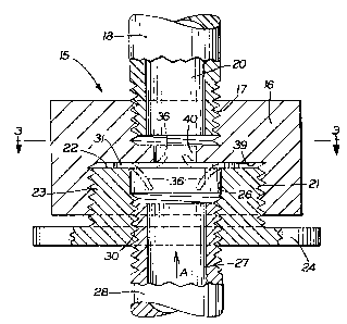
An air ~pring havln~ the lmproved damping valve incorporated
therein i5 indicated generally at 1, and is shown in a first
embodiment shown in ~IGS 1, 2 and 3. Air spring 1 includes a top
dlsc-shaped end memb~r 2 and a ~imilarly shaped botto~ end member
3. A hole 4 may be formed in top end member 2 to provide a
pressurized air inlet opening. A threaded inwardly extending
boss 5 also ~ay be ~ounted on end member 2 to provide a means for
mounting the air spring on a supporting ~tructure of a vehicle
(not ~hownj. A flexible elastomeric ~leeve 7 having reinforced
end beads 8 is secured in an airtlght clamped relationship with
the end members by rolled ends lO ~FIG. 1). Sleeve ~ provides a
pressuri2ed fluid reservoir 12 between the end members. Sleeve 7
is of a usual construction ~ell known in the art and preferably
contains internal fiber reinorcem~nt (not shown) to provide
strength to the ~leeve.
An external reservoir 13 is mounted by an annular collar 14
on bottom end member 3 and contains a supply of compressed fluid,
generally air. The interior of reservoir 13 communicates with
fluid reservoir 12 of sleeve ~ through the improved two-way
damping valve which is indicated generally at 15 (FIG 3A).
Val~e 15 includes a mounting block 16 (FIG. 2) having an upper
threaded opening 17 into which a nipple 18 is en~aged. An
enlarged internally threaded opening 21 i8 formed in the bottom
portion of block 16 in which the shank portion of a threaded
sleeve 23 is engaged. Sleeve 23 terminates in an annular end
collar 24 and is formed with an end bore opening 26 which
communicates with a bore 2~ of a second nipple 28. Nipple 28
also has a threaded outer end which is engaged with an internally
threaded bore 30 of sleeve 23. Block 16 also is formed with a
fixed predetermined gize damping orifice 40 axially aligned with
~3(~
bore~ 20 and 27 of nipples 18 and 28, respectively, and with
enlarged opening ~6 of block 16.
Improved damping valve 15 further includes a flat, pref~rably
disc-shaped pi~ce of material which forms a diaphragm
31 (FI~ 3A). Diaphragm 31 preferably is formed of rubber
reinforced with fiber strands 32 a~d has one or more slots 33.
Various slot arrangements can be used as sho~n ~n FIG. 7 to
achieve various damping characteristics. ~he particular slot
arrangement ~hown in the embodiment of FIGS. 1-3 is a "Y" shaped
arrangement indicated yenerally at 38, as shown in FIG 3, formed
by three slots 33 which merge at a center point 34. The outer
ends of each slot terminate in a circular hole 35 which reduces
tearing of the diaphrag~ and facilitates bendiny of flaps 36
formed by the slots. Three flaps, each of which is indicated
at 36 i8 formed in diaphragm 31 and is defined by two slots 33
and the outer peripheral edge 3~ of the diaphragm.
Diaphragm 31 is maintained within block 16 and is pressed
against an annular surface 39 by annular end surface 22 of sleeve
23. (FIG 2). When in the position of FIG. 2 center point 34 of
slots 33 is in axial alignment with the center of nipple bore 27
and bore 20 of nipple 18.
The operation of improved da~ping valve 15 is shown
diagrammatically in FIG 2. Upon air or other type of fluid
moving from reservoir 13 into fluid pressure chamber 12 in the
direction of Arrow A, which occurs when the end members are
moving axially apart as in rebound, the flaps move inwardly into
damping orifice 40 of block 16. This movement of the flaps
reduces the effective si~e o~ orifice 40 and retards the passage
of fluid therethrough. Thus, the fluid moving from reservoir 13
into fluid reservoir 12 must flow through a restricted passage.
In contrast, when the air or other fluid is moving from reservoir
12 into reservoir 13, as in the jounce position wherein end
member 2 and 3 are moving axially toward each other and are
~3~71~
expelling fluid from reservoir 12, flaps 36 will move into
enlaryed circular opening or bore 26 of block 16 as ~hown by the
lower dot-dash ~lap~ in FIG. 2. rhi~ provides an unrestrlcted
fluid passage through orifice 40 in contrast to the restricted
passage whlch is ~ormed when the ~laps ~ove in the opposite
direction and $nto orifice 40. The fixed ~ize of orifice 40 i5
important in that this determines the damping rate provided by
valve 15 and wlll be larger than adjacent opening 26.
A modified embodiment of an air spring containing the
improved dampins valve is indicated generally at 45, and is shown
in FIGS. 4-6. Modified air spring 45 includes a top end number
46 and a flexible ela~tomeric sleeve 47 which is sealingly
connected to end member 46 by a clamping ring 48. ~he opposite
end of sleeve 47 ~s ~ealingly secured to a lower member indicated
generally at 49, by a second clamping ring 50. A rubber ~umper
51 preferably is mounted on the inner ~urface 52 of end member
~6.
Lower member 49 is provided with a generally cylindrical wall
54 which forms an interior reservoir 55 located within flexible
sleeve 47. The lower end of member 49 includes a base 56 formed
with a plurality of threaded openings 5~ for mounting member 49
on a structural portion o~ a vehicl~ spaced from another portion
of the vehicle on which top end ~ember 46 is secured. A plate 58
i5 secured by a plurality of bolts 59 in an ~pper portion of
base 56 to form the botto~ wall of interior reservoir 55. An air
inlet tube 60 communicates with reservoir 55 through its hollow
bore 61. Tube 60 extends through a complementary shaped hole 62
formed in end wall plate 58 and may have a flanged upper end 63
formed thereon.
In accordance with the invention an improved two-way damping
valve indicated generally at 64, i~ mounted adjacent to an
opening 65 formed in a top wall 66 of lower end number 49. Valve
64 includes an externally threaded male sleeve 68 engaged in a
~3~L7~
--10--
threaded opening 69 of end wall 66 and presses flexlble diaphragm
31 of valve 64 against an annular shoulder ~0 formed between top
wall opening~ ~5 and 69. Diaphragm 31 of modified air spring 45
is ~imilar to the diaphragm mounted in air spring 1 of FIGS. 1 3
S and is shown with the ~ame "Y" ~haped slot configuration 38, but
may have other configurations similar to those shown in FIG 7.
The operation of modified embodiMent 45 is shown
diagrammatically in FIG 6. Sleeve 68 is formed with a
predetermined size damping orifice 72 which is larger than
axially aligned opening 65 of top wall 66. ~laps 36 move into
orifice ~2 when the air or other damping fluid flows from
interior reservoir 55 into fluid pressure reservoir ~4 formed by
sleeve 47 (Arrow C, FIG. 6) which will occur as end members 46
and 49 move axially away from each other. As shown ln Fl~ 6, the
15. ~ovement of flaps 36 into orifice 72 reduces or restricts the
area of the opening restricting the movement of flu$d
therethrough. Upon end members 46 and 49 moving axially toward
each other, air is expelled from pressure reservoir ~4 through
orifice ~2 and into reservoir 55. Upon the air movement in this
direction which is opposite to that of Arrow C, flaps 36 move
away from orifice 72 (shown by dot-dash lines) providing an
unrestricted orifice 72. This provides a damping characteristic
different than that provided upon movement of the end members
away from each other when the fluid flow through restricted
orifice 72.
Bumper 51 prevents end member 46 from direct contact
with top wall 66 of end member 49 and provides a cushioning
effect thereto should end member 46 completely collapse into
contact with the top wall. Also, air inlet tube 60 preferably is
connected to an external supply valve for providillg makeup air
into reservoir 55 when required to achieve various operating
characteristics. The movement of air or other fluid into and out
of reservoir 55 through inlet tube 60 is by a known type of
7~1~
--11--
control valve and supply ~y~tem and, therefore, i~ not ~hown in
the drawing~.
Another modified for~ of the improved two-way damping valve
i6 indicated generally at ~5, with a number of embodiments belng
sho~ in FIG 7. Valve ~5 includes diaphra~ 31 preferably
secured by an adhesive 76 to a annular metal washer 77. Washer
77 has a central opening 7~ which for~s the damping control
orifice similar to orifice 40 of valve 15 and orifice 72 of valve
64. Valve ~5 can be ~ount~d within an air spring and eliminates
the need for the damping control orifice to be formed as an
integral part of the air ~pring body. This enables the damping
characteristics of the air spring to be changed easily by merely
replacing valve 75 with a similar valve, but with a different
size damping orifice 78 ~ithout even changing the external
dimension of washer 77.
Various other damping characteristics can be obtained by
providing diaphragm 31 with a variety of flap configurations,
sizes and arrangements as shown in FIG 7. Diaphragm ~9 has a
single slot 80 which forms a palr of flaps. Diaphra~m 31
includes the Y-6haped slot arrangement shown in the particular
embodiments of FIGS 1-6. Diaphram 82 includes an X-shaped slot
configuration indicated at 83 which ~orms four generally V-
shaped flaps, each of whioh is indicated at 84. Diaphragm 85 is
formed with a U-shaped 510t B6 which forms a single U-shaped
main flap 87 and a surrounding flap 88. Flap 87 provides the
main obstruction it moves into the fixed damping orifice as
described above. A ~till further modiE1ed diaphragm is indicated
at 89 and has a V-shaped slot 90 formed therein which forms a
main V-shaped flap 91 and a surro~nding flap 92.
The various filot conf~gurations formed in the diagrams of
FIG. 7 are representative o~ different configurations that can be
provided, each oE which provides a different damping
characteristic by the effect that the flaps have on the movement
-12-
of air through the fixed damping orific~. Preferably the
diaphragm of FIG. ~ will be ~ounted on a backing washer 7~ to
provide a self-contained valve with the washer opening for~ing
th~ damping orifice.
Another ~luid suspension unit usin~ the improved
two-way damping valve is indicated generally at 95, and is an
air ~prin~ in combination with ~ strut-type fluid shock absorber,
and is shown particularly in FI~S. 8-11. Suspension unit 95
includes an outer cylinder 96 having a vehicle attachment bracket
9~ mounted on the lower end thereof for mounting the unit on a
vehicle. A piston rod 98 is ~ounted within cylinder 96 and i5
formed with a hollow interior 99. The top end of piston rod 98
is connected to a solenoid control valve 100 havi~g a fluid inlet
' opening which communicates with a supply of a compressed fluid,
usually air, for supplying make-up air to the interior of the
piston rod. The upper end of rod 98 and valve 100 is fixed with
respect to an annular mounting cup 103 which is connected to an
outer flange 104 which is fixed to a vehicle in a spaced
relationship from the other portion of the vehicle to which
attachment bracket 97 is secured.
A cylindrical can-like member 105 is mounted by a compression
fit on the lower end of an inverted cup-shaped housing 106 with
the upper end of a elastomeric sleeve 107 being clamped
therebetween. The lower end of sleeve 107 is secured by a
clamping ring 108 to the upper end of outer cylinder 96. The
upper end of housing 106 is connected to a ring cap 102 which is
rotatably mounted with respect to mounting cap 103 by a bearing
(not shown). Thus, ring cap 102, housing 106, sleeve 10~ and
cylinder 96 are rotatably mounted with respect to mounting cap
103 and piston rod 98. A plurality of nylon bearing rings 109
are telescopically mounted on piston rod 98 within cylinder 96
for rotatably mounting the cylinder with respect to the piston
rod. An upper bearing ring 110 ~s located between piston rod 98
`` ~.3~
-13-
and the top end o~ cylinder 96 and i8 secured in position on the
flanged end of a ~pacer ~l~eve 112 by a cap wa~her 111.
plurality of other ~pacer ~leev~s 112~ and 112B ar~ locat~d J
between bearin~ rings iog and at bottom end cap 118 of cylinder
~6 as shown particularly in FIG 11.
A resllient annular bumper 113 preferably 18 bonded to ring
cap 102 and is telescopically, slidably mounted with respect to
the upper end of piston rod 98. Ring cap 102 preferably is
spaced from piston rod 9B by a ~pacer ring 119. Resilient sleeve
lC 107 forms a fluid pressure reservoir 115 which communicates with
the annular space 116 located between piston rod 98 and cylinder
96. It also communicates and with the fluid space or reservoir
117 located beneath the bottom end of pistron rod 98 and bottom
wall llB of cylinder 96. Air ~pring sleeve 10~ i8 used primarily
in suspension unit 95 for regulating the axial ~pacing bekween
mounting bracket 97 and flange 104.
In accordance with one of the features of the invention, a
two-way damping valve indlcated generally at 120, is mounted in
the lower end of piSton rod 98 for controlling the ~ove~ent of
the damping fluid between hollow interior 128 of the piston rod
and reservoir 117 to provide the desired dampin~ characteristics
for suspension unit 95.
Damping valve 120 is similar in many respects to valves 15
and 64 in that it includes flexible rubber diaphragm 31 (FIGS. 9
and 10) having one or more flaps 36 axially aligned with a
predetermined fixed damping orlfice 123 formed in a flanged
washer 124. Washer 124 is clamped against an annular shoulder
125 formed in the bottom end of pi8ton rod 98 by an internally
threaded end cap 126 which is threadably engaged with the lower
end of rod 98. ~nd cap 126 i8 formed with a central openins 12
having a larger diameter than that of fixed damping orifice 123.
Diaphragm 131 as ~hown in FIG lO is formed with the "Y"-shaped
slot arrangement 38 providing three flaps 36. Again, the
7138
-14-
particular configuration of the diaphra~m 810~5 and resulting
fl~ps can vary without af~ecting the concept of the inv~ntion.
The operation of da~ping valve 124 ~s shown in FIG. 9 wherein
~luid movement in the direction of Arrow D will cause flaps 36 to
move into fixed damping orifice 123 to restrict the flow of fluid
there~hrou~h and will move away from the orifice as ~hown by the
lower dot-dash ~laps when the fluid moves ln an opposite
direction to that of Arrow D, that is from piston rod interior 99
into cyl$nder reservoir 117. This provides for the unrestricted
flow oP the fluid through oriflce 123.
The operations of the improved damping valves are shown
diagrammatically in FIGS. 12-1~. The damping valve shown in
FIGS. 12 and 13 consist of diaphragm 31 which is trapped within
an annular cutout 129 formed with a fixed damping orifice 130.
Fluid movement in the direction of Arrow F is restricted by the
flaps entering orifice 130, whereas fluid movement in the
opposite direction as shown in FIG. 13 (Arrow G) is unrestricted
through orifice 130.
FIGS. 14 and 16 show the use of damping valve ~5 consisting
of the flexible resilient diaphragm 31 bonded to washer ~ with
the washer opening 78 forming the damping orifice. Fluid moving
in the direction of Arrow H (FIG. 14) is restricted, whereas
fluid flowing in the direction of Arrow I (FIG. 15) is restricted
only by the predetermined size of orifice 78.
Thus the improved damping valve can either restrict or permit
the flow of fluid o~ an air ~u~pension unit in either direction
between the fluid pressure reservoir formed by a flexible sleeve
and an auxiliary fluid reservoir located either externally as
shown in FIG. 1 or internally as shown in FIG. 4, or in
combination with a reservoir provided in the bottom of cylinder
96, to achieve various desired damping characteristics for the
suspension unit. The improved damping valve is an extremely
simple, inexpensive and nearly maintenance-free de~ice which will
3~
-15-
usually outlive the llfe of the suspenslon unit in which it is
~ount2d. The device can provide variou~ damping cAaracteristics
by c~an~ing the 6ize of the fixed damping orifice or by ohanglng
the flap con~iguration a~ shown in FI¢ 7 to provide various flap
arrangements by different ~lot arrangements. The u~e of a
circular hole at the ends of the 1ap forming ~lots provides
greater flexibility to the flaps while reducing tearing of the
diaphrag~.
Although air will be th~ preferred fluid ~or the various
suspension units described above, other fluids could be ~sed
without affecting the concept of the invention. The improved
device provides damping for an air ~pring alone or combined
with a shock absorber strut comparable to that provided by an
external hydraulic shock absorber for a minimum cost and wlth
very little effect on the natural frequency and lateral or
vertical movement of the flexible sleeve portion of the unit.
The damping valve can be used either for damping during the
compression or extended condition, and the d~aphragm can be used
either with or without a metal washer.
The improved damping valves 15, 6~, ~5 and 120 can be mounted
by various arrangements between the preasurized fluid reservoir
of the air spring sleeve and auxillary reservoir by means other
than shown in the drawing3 and described above. I~ desired the
valve can be bonded into a rubber mount or other mechanical
mounting device without affecting the concept of the invention.
Accordingly, the ~mproved damping valve is simplified,
provides an effective, ~afe, inexpensive, and efficient device
which achieves all the enumerated objectives, provides for
eliminating difficulties encountered with prior dev~ces, and
solves problems and obtains new results in the art.
In the foregoing description, certain terms have been used
for brevity, clearness and understanding; but no unnecessary
limitations are to be implied therefrom beyond the reguirements
-16-
of the prior art, becau~e ~uch terms are used for descript~ve
purposes and are intended to be broadly construed,
Moreover, the description and illustration of the invention
is by way of exa~ple, and the scope o~ the invention i5 not
limited to the exact details shown or described.
Having now described the ~eatures, di~coveries and p~inciples
of the invention, the ~anner ln which the i~proved damping
valve for alr spring suspension syctems ls constructed and used,
the characteristics of the co~struction, and the advantageous,
new and useful results obtained; the new and useful structures,
devices, elements, arrangements, parts, and combinations, are set
forth in the appended claims.