Language selection

Search

Patent 1302392 Summary

Third-party information liability

Some of the information on this Web page has been provided by external sources. The Government of Canada is not responsible for the accuracy, reliability or currency of the information supplied by external sources. Users wishing to rely upon this information should consult directly with the source of the information. Content provided by external sources is not subject to official languages, privacy and accessibility requirements.

Claims and Abstract availability

Any discrepancies in the text and image of the Claims and Abstract are due to differing posting times. Text of the Claims and Abstract are posted:

  • At the time the application is open to public inspection;
  • At the time of issue of the patent (grant).
(12) Patent: (11) CA 1302392
(21) Application Number: 538370
(54) English Title: GANG DRILL CONSTRUCTION
(54) French Title: ASSEMBLAGE REGROUPANT PLUSIEURS PERFORATRICES DE ROCHES
Status: Deemed expired
Bibliographic Data
(52) Canadian Patent Classification (CPC):
  • 255/68
(51) International Patent Classification (IPC):
  • E21B 4/16 (2006.01)
  • E21B 10/38 (2006.01)
(72) Inventors :
  • KURT, EWALD HEINZ (United States of America)
(73) Owners :
  • INGERSOLL-RAND COMPANY (United States of America)
(71) Applicants :
(74) Agent: SWABEY OGILVY RENAULT
(74) Associate agent:
(45) Issued: 1992-06-02
(22) Filed Date: 1987-05-29
Availability of licence: N/A
(25) Language of filing: English

Patent Cooperation Treaty (PCT): No

(30) Application Priority Data:
Application No. Country/Territory Date
06/922,626 United States of America 1986-10-24

Abstracts

English Abstract


GANG DRILL CONSTRUCTION

ABSTRACT

Disclosed is a new method of construction for multiple or
gang down hole rock drills. A rigid mounting cylinder with
alignment and securing means for the individual drills is
provided. The cylinder further serves to attach the multiple
drills to a single drill string which supplies air to the
individual drills. The cylinder further facilitates rock chip
removal by filling all but the peripheral annulus which forms
the exit channel for exhaust air.


Claims

Note: Claims are shown in the official language in which they were submitted.

The embodiments of the invention in which an exclu-
sive property or privilege is claimed are defined
as follows:-

1. A gang drill for rock boring and the like
comprising:
an assembly of a plurality of individual
percussion producing rock drills in a cylindrical
drill casing having a top end connected to a drill
string and a bottom end adjacent rock boring bits
operatively associated with each of said drills; said
casing totally enclosing said percussive producing
rock drills, and being further provided with alignment
means, securing means and means for supplying pressure
fluid for each of said drills of said plurality of
drills, said pressure fluid entering said drills
internal of said casing and exiting said drills
external to said casing at its bottom end whereby said
casing forms a peripheral passage for the exiting of
rock cuttings and provides protection for said drills.

2. The gang drill according to claim 1 further
characterized in said casing having inserted therein a
center drill and a plurality of peripheral drills.

3. The gang drill according to claim 2 further
characterized in that each of said peripheral drills
is provided with an alignment taper at one end, means
for securing said peripheral drills to a mating
alignment plate at one end of said casing having
corresponding tapers, and a locking means at its other
end for securing said peripheral drills against
rotation within said gang drill casing.

4. The gang drill according to claim 3 wherein
said locking means comprises a key inserted between
said peripheral drill and a key plate at the other end
of said casing.

-7-

Description

Note: Descriptions are shown in the official language in which they were submitted.


~3()2~92


BACKGROUND AND OB~ECT OF THE INVENTION

Down the hole (downhole) drills have found wide
acceptance in drilling rock in hole sizes to twenty
four (24) inches. In larger sizes economics of
producing the limited numbers involved have further
limited down hole drill acceptance.
It is therefore an object of this invention to
produce an effective down hole drill of larger
diameter and lower cost.
An object of the invention is to effectively
combine or gang a plurality of smaller economically
manufactured drills in a versatile package suitable
for drill string attachment as a down the hole drill.
These and other objects are obtained in a gang
drill for rock boring and the like and comprised of an
assembly of a plurality of individual percussion
producing rock dri'ls in a cylindrical drill casing
having a top end connected to a drill string and a
bottom end adjacent rock boring bits operatively
associated with each of the drills. The casing
totally encloses the percussive producing rock drills
and is further provided with alignment means, securing
means and means for supplying pressure fluid for each
of the drills of the plurality of drills. The
pressure fluid enters the drills internal of the
casing and exits the drills external to the casing at
its bottom end whereby the casing forms a peripheral
passage for the exiting of rock cuttings and provides
protection for the drills.

DESCRIPTION OF THE DRAWINGS

Figure 1 is a longitudinal section of a gang
drill according to the invention;


i
B

~3023g2


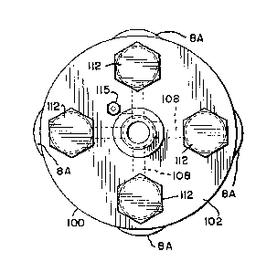
Figure 2 is a top end view of the gang drill;
Figure 3 is a bottom end view of the gang
drill;
Figure 4 is a perspective view of the modified
individual drill used in the gang drill; and


'~
B

130239Z


Figure 5 is a detailed view of the chuck key inserted
in the chuck plate.

DESCRIPTION OF T}IE PREFERRED EMBODIMENT

Referring now to Figure 1, the gang down hole drill of
the present invention is shown for purpose of understanding
the invention in terms of a preferred embodiment. The
embodiment shown compr~ses an exterior cylinder casing 100
having a disc shaped key plate 101 attached by well known
means such as welding at its one end and a disc shaped end
plate 102 attached by well known means at its other end. In
the embodiment shown the key plate is provided with five
straight through circular bores 103. The end plate is
similarly provided with four tapered circular bores 104 in
the periphery and one compound bore in the center in spaced
apart, axial and radial register with the bores in the key
plate.

Inserted in each of the peripheral bores is a down the
hole fluid actuated impact tool or drill 1 of the type
described in U.S. Patent #4,084,646 issued to Ewald Heinz
Kurt and assigned to Ingersoll-Rand Company. The drill is
provided with a modified back head and a modified drill
chuck. Otherwise, the drill may be considered as described
in U.S. Patent #4,084,646 in both structure and function.

As best seen in Figures 1 and 2 the modified back head
of each peripheral drill is provided with a taper 106 having
interconnecting bores 107 which mate with pressure fluid
supply bores 108 in the end plate 102. The pressure fluid
supply bores 108 connect with the central pressure fluid
supply bore 109 which receives pressure fluid from a conven-
tional drill string not shown via the connecting pipe thread
coupling 110.

1302392


The modi~ied backhead 3A e~tends through the end plate 1~2
and terminates in a thread 111 which is used to secure the rock
drill 1 to the end plate by the co-action of the taper 106 and
threaded cap nut 112.

The end plate 102 is further provided with a relief bore 114
which is closed by a relief valve 115 whose function is to
mainta n a slight positive p-essure in 'che d~i;l csi..-3 loo.
The drill casing 100 is f:urt:ler provided with a cencra'.izi..~
support plate 116 which like the key plate lo, and tne end plate
102, are provided with five circular through bores 117. The
centralizing plate 116 is welded to the casing loO in spaced
apart axial and radial register with the bores in the key plate
101 and end plate 102.

As best seen in Figures 4 and 5 each of the peripheral bores
in the key plate 101 is further provided with a key notch 120
which accepts a key 125 having a cylindrical portion 126 and a
rectangular portion 127 as shown on figure 4. The rectangular
portion 127 fits in the key notch 120 and when the drill 1 is
drawn tightly into the taper of end plate 102 by means of the
thread 111 and thread cap nut 112 provide a locking means for
preventing rotation of the drill 1 within the casing 100 during
normal operation. The circular portion 126 of the key 125 is
inserted in the drill chuck of the conventional drill in a
circular bore 128 which according to the present invention is
provided for that purpose.

In the drill chuck 9A, .it should be appreciated by one
skilled in the art that the key 125 in cooperation with the
square notch 120 in the key plate 101 and the circular bore 128
in the drill chuck 9A prevents rotation of the individual down
the hole drills 1 in the gang drill casing 100.

13~ 392


The center drill lC is of similar construction to the
peripheral drills 1 and is provided with a modified drill chuck
lC and a modified backhead 3C. The modified drill chuck 1~ has
an external thread 130 which cooperates tJith a threaded bore 131
in the key plate~ The threaded combination retains the center
drill. In the gang drill casing the backhead 3C is provided
with a centralizing boss 132 which is disposed in assembled
config~ra;_ion ir. the bcre 1~3 w`n cn supplies pr2ssurC fluid to
both the central drill and the per.iphe al drills. In t.~e ~..g
drill combination, pressure fluid is supplied from bore 109 to
the central drill lC through pressure fluid ~ores 107C provided
in the backhead 3C.

In the preferred embodiment sho~n the drill bit 8A is of
slightly larger diameter t~lan the drill for the peripheral
drills while the central drill lC is provided with a drill bit
8C which is of approximately the same diameter as the central
drill. The larger diameter drill bits 8A provide the necessary
overlap of tne gang drill casing 100 rzquired to permit the
casing 100 to pass into the bored hole. Use o~ the ~smalle.
diameter bit on the central drill is for convenience in the
present package arrangement. The size of the center drill
shoul!d be selected to permit approximately equal cutting advance
with the peripheral drills while minimizing the open or
non-active cutting space on the drill face.

As can be appreciated by one skilled in the art, the present
invention provides a means of ganging a number of smaller
diameter rock drills in a convenient and aligned package to bore
larger size holes. The package further permits use with
conventional drill strings having a single central pressure
fluid suppl~1 and string mounting means.

~ 130Z39Z

.. .. . . ~ . .


Having now described my invention in terms of a preferred
embodiment, however, I do not wish to be limited in the scope of
my invention except as claimed.

Representative Drawing
A single figure which represents the drawing illustrating the invention.
Administrative Status

For a clearer understanding of the status of the application/patent presented on this page, the site Disclaimer , as well as the definitions for Patent , Administrative Status , Maintenance Fee  and Payment History  should be consulted.

Administrative Status

Title Date
Forecasted Issue Date 1992-06-02
(22) Filed 1987-05-29
(45) Issued 1992-06-02
Deemed Expired 1998-06-02

Abandonment History

There is no abandonment history.

Payment History

Fee Type Anniversary Year Due Date Amount Paid Paid Date
Application Fee $0.00 1987-05-29
Registration of a document - section 124 $0.00 1987-08-19
Maintenance Fee - Patent - Old Act 2 1994-06-02 $100.00 1994-05-13
Maintenance Fee - Patent - Old Act 3 1995-06-02 $100.00 1995-05-11
Maintenance Fee - Patent - Old Act 4 1996-06-03 $100.00 1996-05-16
Owners on Record

Note: Records showing the ownership history in alphabetical order.

Current Owners on Record
INGERSOLL-RAND COMPANY
Past Owners on Record
KURT, EWALD HEINZ
Past Owners that do not appear in the "Owners on Record" listing will appear in other documentation within the application.
Documents

To view selected files, please enter reCAPTCHA code :


To view images, click a link in the Document Description column. To download the documents, select one or more checkboxes in the first column and then click the "Download Selected in PDF format (Zip Archive)" or the "Download Selected as Single PDF" button.

List of published and non-published patent-specific documents on the CPD .

If you have any difficulty accessing content, you can call the Client Service Centre at 1-866-997-1936 or send them an e-mail at CIPO Client Service Centre.


Document
Description 
Date
(yyyy-mm-dd) 
Number of pages   Size of Image (KB) 
Representative Drawing 2002-01-29 1 11
Description 1993-10-30 6 173
Drawings 1993-10-30 2 72
Claims 1993-10-30 1 38
Abstract 1993-10-30 1 16
Cover Page 1993-10-30 1 11
Fees 1996-05-16 1 41
Fees 1995-05-11 1 41
Fees 1994-05-13 1 31