Language selection

Search

Patent 1302518 Summary

Third-party information liability

Some of the information on this Web page has been provided by external sources. The Government of Canada is not responsible for the accuracy, reliability or currency of the information supplied by external sources. Users wishing to rely upon this information should consult directly with the source of the information. Content provided by external sources is not subject to official languages, privacy and accessibility requirements.

Claims and Abstract availability

Any discrepancies in the text and image of the Claims and Abstract are due to differing posting times. Text of the Claims and Abstract are posted:

  • At the time the application is open to public inspection;
  • At the time of issue of the patent (grant).
(12) Patent: (11) CA 1302518
(21) Application Number: 1302518
(54) English Title: PLASMA FIRED FEED NOZZLE
(54) French Title: INJECTEUR DE CHAUFFE AU PLASMA
Status: Term Expired - Post Grant
Bibliographic Data
(51) International Patent Classification (IPC):
  • H05H 1/34 (2006.01)
  • B05B 7/22 (2006.01)
  • C21B 5/00 (2006.01)
  • C21B 13/12 (2006.01)
  • F27D 1/16 (2006.01)
  • H05H 1/42 (2006.01)
(72) Inventors :
  • DIGHE, SHYAM VASANT (United States of America)
  • WOLF, CHARLES BERNARD (United States of America)
(73) Owners :
  • WESTINGHOUSE ELECTRIC CORPORATION
(71) Applicants :
  • WESTINGHOUSE ELECTRIC CORPORATION (United States of America)
(74) Agent: SMART & BIGGAR LP
(74) Associate agent:
(45) Issued: 1992-06-02
(22) Filed Date: 1988-05-06
Availability of licence: N/A
Dedicated to the Public: N/A
(25) Language of filing: English

Patent Cooperation Treaty (PCT): No

(30) Application Priority Data:
Application No. Country/Territory Date
047,811 (United States of America) 1987-05-08

Abstracts

English Abstract


9 53,093
ABSTRACT OF THE DISCLOSURE
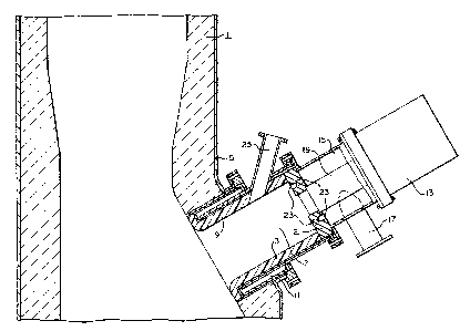
A plasma feed nozzle 3 for a furnace 1 which has
a tubular mixing chamber 7 open at one end to the furnace,
a plasma torch 13 which provides superheated gases axially
to the central portion of the mixing chamber 7, shroud
gases which enter the end of the mixing chamber opposite
the end open to the furnace in such a way as to swirl as it
moves axially through the mixing chamber 7 to provide a
temperature profile which is substantially hotter in the
central portion of the mixing chamber 7 than adjacent the
wall portion thereof and a particulate feed nozzle 25
disposed to direct particulate material to the central
portion of the mixing chamber.


Claims

Note: Claims are shown in the official language in which they were submitted.

6 53,093
What is claimed is:
1. A plasma feed nozzle for a furnace, said
plasma feed nozzle comprising:
a plasma torch for producing a superheated gas at
a temperature in the range of 10,000°F (5538°C);
a conduit for shroud gas;
a tubular mixing chamber in fluid communication
with said superheated gas and said conduit for shroud gas
and having one end thereof open to said furnace;
said mixing chamber being lined with a refractory
material and being generally encircled by a cooling fluid
jacket;
means for introducing said superheated gas from
said plasma torch and said shroud gas from said conduit
into said mixing chamber so that the temperature profile of
said gases flowing through said mixing chamber is substan-
tially hotter in the central portion of said mixing chamber
than adjacent said refractory lining, said gases flowing
generally axially through said mixing chamber and into said
furnace with a swirling motion.
2. A plasma feed nozzle as set forth in claim 1
and further comprising a particulate material feed nozzle
disposed in fluid communication with said mixing chamber in
such a manner that the particulate material is introduced
into said mixing chamber so that the particulate material
generally flows axially through the central hottest portion
of the mixing chamber and into the furnace.

7 53,093
3. A plasma feed nozzle as set forth in claim 2,
wherein the furnace is lined with refractory material and
the mixing chamber extends at least partially through the
furnace refractory lining.
4. A plasma feed nozzle as set forth in claim 3,
wherein the plasma torch is disposed so that the super-
heated gas therefrom enters the mixing chamber along its
central axis and the shroud gas enters the mixing chamber
radially outwardly from the superheated gas and in such a
manner to swirl around the superheated gas as the shroud
gas moves axially through the mixing chamber.
5. A plasma feed nozzle as set forth in claim 4
and further comprising a plenum chamber disposed on the end
of the mixing chamber opposite the end open to the furnace,
the plenum chamber being in fluid communication with the
shroud gas conduit and the mixing chamber.
6. A plasma feed nozzle as set forth in claim 5,
wherein there is an opening between the mixing chamber and
the plenum chamber and the plasma torch is so disposed that
the portion thereof from which superheated gas is provided
is aligned with the opening and at least partially within
the plenum chamber.
7. A plasma feed nozzle as set forth in claim 6,
wherein the portion of the plasma torch from which the
superheated gas is provided generally fills the large
opening and there is a separator wall with a plurality of
ports 5 disposed radially outwardly of the opening and the
ports are oriented to cause the shroud gas to swirl as it
enters the mixing chamber.
8. A plasma feed nozzle as set forth in claim 6,
wherein the portion of the plasma torch which supplies the
superheated gas is disposed adjacent the large opening so
as to provide an annular space between the portion of the
plasma torch which supplies the superheated gas and the
large opening and the shroud gas conduit is connected to
the plenum chamber tangentially whereby the shroud gas

8 53,093
swirls in the plenum chamber and as it passes through the
annular opening into the mixing chamber.
9. A plasma feed nozzle as set forth in claim 8,
wherein the tubular mixing chamber is tapered so that the
end open into the furnace is smaller than the end adjacent
the plenum chamber.
10. A plasma feed nozzle as set forth in claim
8, wherein the particulate matter feed conduit is connected
to the tubular portion of the mixing chamber and is dis-
posed at an angle with respect to the axis of the mixing
chamber biasing the particulate material introduced thereby
in the direction of the furnace.
11. A plasma feed nozzle as set forth in claim
10, wherein the particulate material feed also introduces a
carrier gas with the particulate material.
12. A plasma feed nozzle as set forth in claim
11 wherein the angle of the particulate feed conduit is
dependent upon the density and size of the particulate
material, the carrier gas flow and viscosity and the flow
rate of the superheated gas and shroud gas.
13. A plasma feed nozzle as set forth in claim
7, wherein said particulate material feed nozzle is dis-
posed to extend through said plenum chamber and have a
discharge portion which is generally parallel to the axis
of the feed nozzle and discharge into said mixing chamber.
14. A plasma feed nozzle as set forth in claim
7, wherein said particulate material nozzle is generally
disposed at the elevation of the axis of the feed nozzle.
15. A plasma feed nozzle as set forth in claim
7, wherein said particulate feed nozzle is generally
disposed at an elevation above the axis of the feed nozzle.
16. A plasma feed nozzle as set forth in claim
12, wherein the particulate feed conduit enters the upper
portion of the mixing chamber.
17. A plasma feed nozzle as set forth in claim
13 wherein there are a plurality of particulate feed
conduits entering the upper portion of the mixing chamber.

Description

Note: Descriptions are shown in the official language in which they were submitted.


~1 3~25i~L8
1 53,093
PLASMA FIRED FEED NOZZLE
BACKGROUND OF THE INVENTION
This lnvention relates to a feed nozzle for a
furnace and more particularly to a plasma feed nozzle for a
cupola. As described in United States Patent No. 530,101
by M. G. Fey and T. N. Meyer, heat from an electric arc can
be fed into a cupola or other furnace to enhance the
operation thereof by providing a very hot gas stream which
may be either oxidizing or reducing and can also be mixed
with particulate material. The electric arc is produced in
a plasma torch in which the electric arc ionizes the gas
which is blown out of the end of the torch producing a
white hot gas stream which generally operates in the range
of 10,000E or 5,538C. Such temperatures are maintained
for hours or days in a relatively small diameter feed
nozzle without destroying the refractory material which
line the nozzle. Refractory material normally begins to
soften about 2,900F or 1595C about one-third of the
temperature of the superheated gas stream from the plasma
torch.
Particulate material fed into the superheated
stream melts rapidly providing expeditious rapid changes to
the chemistry of molten met~l in a cupola or other type of
furnace.
SUMMARY OF THE INVENTION
In general, a plasma torch feed nozzle for a
furnace, when made in accordance with this invention,
. . ,

~.3~2~
~ 53,093
comprises a plasma torch for producing a superheated gas at
a temperature in the range of 10,000F or 5538C, a conduit
for shroud gas; a tubular mixing chamber in fluid communi-
cation with the superheated gas and the conduit for shroud
gas and has one end open to the furnace. The mixing
chamber is lined with refractory material and is generally
encircled by a cooling fluid jacket. The superheated gas
from the plasma torch and the shroud gas from the conduit
are introduced into the mixing chamber in such a manner
that the temperature profile of the gases is substantially
hotter in the central portion of the mixing chamber than
adjacent the refractory lining as the gas flows axially
through the mixing chamber and into the furnace.
BRIEF ~ESCRIPTION OF THE DRAWINGS
The objects and advantages of this invention will
become more apparent by reading the following detailed
description in conjunction with the accompanying drawings,
in which:
Figure 1 is a partial sectional view of a cupola
with a plasma fired nozzle disposed therein;
Fig. 2 is an alternative embodiment of the cupola
with a plasma fired nozzle disposed therein;
Fig. 3 is an enlarged sectional view of the
nozzle;
Fig. 4 is a sectional view taken on line IV-IV of
Fig. 3;
Fig. 5 is a sectional view taken on line V-V of
Fig. 3;
Fig. 6 is an alternative embodiment of the cupola
with a plasma fired nozzle shown in Fig. 3 disposed
therein;
Fig. 7 is an alternative embodiment of the
nozzles shown in Fig. 2;
Fig. 8 is a sectional view taken on line
VIII-VIII of Fig. 7;
Fig. 9 is an alternative embodiment of the nozzle
shown in Fig. 7; and

~L3~
3 53,093
Fig. 10 is a sectional view taken on line X-X of
Fig. 9.
DESCRIPTION OF THE PREFERRED EMBODIMENTS
Referring now to the drawings in detail and in
particular to Fig. 1 there is shown a portion cf a furnace
such as a cupola 1 with a plasma feed nozzle or tuyere 3
attached to a side wall 5 thereof. The feed nozzle 3
comprises a tubular mixing chamber 7 lined with one or more
layers of refractory 9 and encircled by a cooling jacket 11
through which a cooling fluid such as water is passed. The
mixing chamber 7 has one end thereof open into the furnace
1. A plasma torch 13 is disposed in the end of the mixing
chamber 7 opposite the end into the furnace. Also disposed
on the end of the mixing chamber opposite the end opening
into the furnace is a plenum chamber 15.
Shroud air or process gas is introduced into the
plenum chamber 15 preferably through a shroud gas inlet
nozzle 17 tangentially disposed with respect to the plenum
chamber 15. The plasma torch 13 such as the *Marc II
manufactured by Westinghouse Electric Corporation has a
plasma nozzle lg which extends through the plenum chamber
15 to provide a blast of flame-like superheated gas to the
central portion of the mixing chambers 7. The temperature
of the superheated gas entering the mixing chamber is
generally in the range of 10,000F (5,538C).
As shown in Fig. 1 there is a refractory separa-
tor 21 disposed between the mixing chambers 7 and the
plenum chamber 15 with a plurality of inclined ports 23
disposed introduce the shroud gas into the mixing chambers
7 in such a manner that the shroud gas swirls as it pro-
gresses axially through the mixing chamber 7 and the
superheated gas from the plasma torch 13 is introduced
along the axis of the mixing chamber 7 also swirling so
that a gas temperature profile across the mixing chamber 7
is substantially hotter in the central portion thereof than
adjacent the refractory walls 9.
e ~

- ~3~5~1~
4 53,093
A particulate material feed nozzle 25 is disposed
in fluid communication with the mixing chamber 7 and the
axis thereof forms an acute angle with the axis of the
mixing chamber 7 the angle being determined by the density,
size, velocity and viscosity of the particulate material
and transporting fluid which is adjusted to direct the
influent feed material to the central portion of the mixing
chamber 7 where the temperature is the hottest to rapidly
raise the temperature of the influent particulate material.
As shown in Fig. 1 the mixing cham~er 7 may
extend at least partially through the refractory lining of
the furnace or as shown in Fig. 2, the mixing chamber may
abut the furnace's outer wall and there is an opening 31 in
the furnace wall and refractory lining 5 which registers
with the open end of the mixing chamber 7a.
As shown in Fig. 3, the mixing chamber 7b may be
made with walls which taper inwardly toward the open end
and there is no separator wall between the plenum chamber
15b and the mixing chamber 7b, but there i5 an annular
opening 35 between the refractory wall 9b and the nozzle l9
of the plasma torch 13. The tangentially disposed shroud
gas nozzle 17 as shown best in Fig. 5 provides a swirling
motion to the shroud gas entering the plenum chamber 15
producing a temperature profile across the mixing chamber
7b which is substantially hotter in the central portion
thereof than adjacent the refractory walls 9b. The re~rac-
tor~ walls 9b of the mixing chamber 7b may be made of two
or more refractory liners facilitating replacement o~ the
inner lining which is subject to wear.
There may be a plurality of feed material nozzles
25 as shown in Fig. 4, each of which is disposed to form a
predetermined acute angle with the axis of the mixing
chamber 7b to direct the material to the central portion of
the mixing chamber where the temperature is the hottest.
Figs. 7 and 8 show a mixing chamber 7a, plenum
chamber 15 and separator 21 similar to those shown in Fig.
2 with the exception that the feed nozzles 25a extend

~L3~ 3L8
53,093
through the separator 21 on either side of the plasma
nozzle l9 generally parallel to the axi.s of the mixing
chamber.
In Figs. 9 and lO, the feed nozzles 25b enter
through the separator 21 generally above the plasma nozzle
19 and are generally parallel to the axis of the mixing
chamber as they extend adjacent thereto.
The plasma feed nozzles hereinbefore described
advantageously provide for the introduction of an extremely
high temperature superheated gas in a confined space in
which feed material can be rapidly heated and yet the
refractory walls are relatively cool providing reasonable
lengths of service.

Representative Drawing
A single figure which represents the drawing illustrating the invention.
Administrative Status

2024-08-01:As part of the Next Generation Patents (NGP) transition, the Canadian Patents Database (CPD) now contains a more detailed Event History, which replicates the Event Log of our new back-office solution.

Please note that "Inactive:" events refers to events no longer in use in our new back-office solution.

For a clearer understanding of the status of the application/patent presented on this page, the site Disclaimer , as well as the definitions for Patent , Event History , Maintenance Fee  and Payment History  should be consulted.

Event History

Description Date
Inactive: IPC expired 2016-01-01
Inactive: Expired (old Act Patent) latest possible expiry date 2009-06-02
Inactive: IPC from MCD 2006-03-11
Grant by Issuance 1992-06-02

Abandonment History

There is no abandonment history.

Owners on Record

Note: Records showing the ownership history in alphabetical order.

Current Owners on Record
WESTINGHOUSE ELECTRIC CORPORATION
Past Owners on Record
CHARLES BERNARD WOLF
SHYAM VASANT DIGHE
Past Owners that do not appear in the "Owners on Record" listing will appear in other documentation within the application.
Documents

To view selected files, please enter reCAPTCHA code :


To view images, click a link in the Document Description column. To download the documents, select one or more checkboxes in the first column and then click the "Download Selected in PDF format (Zip Archive)" or the "Download Selected as Single PDF" button.

List of published and non-published patent-specific documents on the CPD .

If you have any difficulty accessing content, you can call the Client Service Centre at 1-866-997-1936 or send them an e-mail at CIPO Client Service Centre.


Document
Description 
Date
(yyyy-mm-dd) 
Number of pages   Size of Image (KB) 
Drawings 1993-10-31 7 165
Cover Page 1993-10-31 1 13
Claims 1993-10-31 3 120
Abstract 1993-10-31 1 18
Descriptions 1993-10-31 5 177
Representative drawing 2001-10-22 1 17
Fees 1997-05-12 1 196
Fees 1996-05-16 1 95
Fees 1995-05-30 1 130
Fees 1994-03-29 1 121