Language selection

Search

Patent 1302843 Summary

Third-party information liability

Some of the information on this Web page has been provided by external sources. The Government of Canada is not responsible for the accuracy, reliability or currency of the information supplied by external sources. Users wishing to rely upon this information should consult directly with the source of the information. Content provided by external sources is not subject to official languages, privacy and accessibility requirements.

Claims and Abstract availability

Any discrepancies in the text and image of the Claims and Abstract are due to differing posting times. Text of the Claims and Abstract are posted:

  • At the time the application is open to public inspection;
  • At the time of issue of the patent (grant).
(12) Patent: (11) CA 1302843
(21) Application Number: 1302843
(54) English Title: ROTATOR FOR CRANE-MOUNTED WORKING IMPLEMENTS ESPECIALLY TREE-PROCESSING UNITS
(54) French Title: DISPOSITIF DE ROTATION POUR OUTILS MONTES SUR GRUE
Status: Term Expired - Post Grant
Bibliographic Data
(51) International Patent Classification (IPC):
  • B66C 13/08 (2006.01)
  • A01G 23/08 (2006.01)
  • B66C 3/00 (2006.01)
  • F15B 15/12 (2006.01)
(72) Inventors :
  • HANSSON, ROLF (Sweden)
(73) Owners :
  • INDEXATOR AKTIEBOLAG
(71) Applicants :
  • INDEXATOR AKTIEBOLAG (Sweden)
(74) Agent: OSLER, HOSKIN & HARCOURT LLP
(74) Associate agent:
(45) Issued: 1992-06-09
(22) Filed Date: 1988-12-12
Availability of licence: N/A
Dedicated to the Public: N/A
(25) Language of filing: English

Patent Cooperation Treaty (PCT): No

(30) Application Priority Data:
Application No. Country/Territory Date
8705170-2 (Sweden) 1987-12-28

Abstracts

English Abstract


ABSTRACT
A rotator for crane-mounted working implements
comprises a housing (7) swingably connectible with the
tip of the crane via a joint, and a pivot shaft (8)
connectible with the working implement and pivotal rela-
tive to said housing by means of at least one vane or
flap (10) operating in a chamber and dividing said cham-
ber into two operating chambers which can be supplied
with, or evacuated of, hydraulic medium via two first
ducts (12) provided in said housing, said pivot shaft
including second hydraulic medium through-ducts (17,
17') opening into annular hollow spaces (16, 16') in
a swivel connection (15) incorporated in said housing.
Between said first ducts (12) in the housing and the
annular hollow spaces (16, 16') of the swivel connection
(15), branch ducts (20) are provided for establishing
communication between said first and said second ducts
12, 17) for supplying hydraulic medium to the rotator
working chambers via said shaft (8), thereby eliminating
the need for any hydraulic medium connection on the
outside of the rotator housing.


Claims

Note: Claims are shown in the official language in which they were submitted.

THE EMBODIMENTS OF THE INVENTION IN WHICH AN EXCLUSIVE
PROPERTY OR PRIVILEGE IS CLAIMED ARE DEFINED AS FOLLOWS:
1. In a rotator for a crane mounted device, in
which said crane includes a crane tip and said rotator
includes a housing connected with said crane tip, and
wherein said rotator has a pivot shaft pivotable relative
to said housing, a chamber within said housing, said
chamber having at least one vane dividing said chamber
into at least two sub-chambers, a pair of first duct
means in said housing for supplying said sub-chambers
with and evacuating said sub-chambers of a hydraulic
medium, a swivel connection in said housing, said swivel
connection having at least two hollow chambers, and said
pivot shaft including second duct means in fluid
communication with said hollow chambers, the improvement
wherein said rotator includes branch duct means in fluid
communication between said first duct means and said
hollow chambers of said housing, said branch duct means
allowing fluid communication between said first and said
second duct means to thereby supply hydraulic medium to
said sub-chambers via said pivot shaft thereby
eliminating external hydraulic medium connections on the
outside of said housing.
2. The apparatus as claimed in claim 1, wherein
said second duct means comprises a pair of ducts.

Description

Note: Descriptions are shown in the official language in which they were submitted.


~3(~28~3
ROTATOR FOR CRANE-MOUNTED WORKING IMPLEMENTS, ESPECIALLY
TREE-PROCESSING UNITS
Technical field of the invention
_
This invention relates to a rotator for crane-
mounted working implements, especially tree-processing
units, comprising a housing swingably connectible with
the tip of the crane via a joint, and a pivot shaft
connectible with the working implement and pivotal
relative to said housing by means of at least one vane
or flap operating in a chamber and dividing said chamber
into two operating or sub-chambers which can be supplied
with, or evacuated of, hydraulic medium via two first
ducts provided in said housing, said pivot shaft in-
cluding second hydraulic medium through-ducts opening
- into annular hollow spaces in a swivel connection in-
corporated in said housing.
Background art
Conventional rotators of the above type comprise
two types of conduits, viz. a first pair of hoses for
~ supplying (supply and evacuation) the rotor working
chamber with hydraulic oil, and a second pair of hoses
for supplying one or more hydraulic cylinders for the
moving parts of the working implement, viz. via the
swivel connection and the ducts opening thereinto and
extending inwardly through the pivot axis of the rotator
down to suitable connections on the implement. Both
pairs of hoses are connected to the outer side of the
rotator top via protruding angular nipples which of
necessity are mounted on the outside of the essentially
cylindrical surface extending downwardly a distance
from the flat upper side of the rotator housing because
the space above the flat upper side is mainly taken
up by the joint by which the rotator is attached to
the crane tip. In the last few years, the hydraulic
oil supply hoses to the working implement have been
_ ..

~3~ 2843
run from the pump and the associated tank on the vehicle
which carries the crane, directly to the working
implement, and not via the swivel connection in the
rotator. In these cases, the connection holes for this
pair of hoses were plugged. Nevertheless, there always
remained on the housing or the top of the rotator the two
nipple-connected oil supply hoses to the rotator proper,
and in practice these hoses constitute a problem of
considerable difficulty when the working implement is a
tree-processing unit, for example a grapple harvester
which, on certain occasions, must hold a stem in a
vertical position during movement from one angular
position to another by means of the rotator. On such
occasions, it frequently happens that the stem comes into
contact both with the nipples radially protruding from
the rotator top and with the hoses connected with the
nipples. As a result, damage is done not only to the
stem (gashes in the surface wood with the ensuing loss of
quality) but also to the hoses and the nipples. This
means that the nipples must be frequently serviced, which
is expensive, and if the damage is so serious that
leakage occurs, the tree-processing unit is no longer
saft to operate.
In accordance with an embodiment of the present
invention there is provided in a rotator for a crane
mounted device, in which the crane includes a crane tip
and the rotator includes a housing connected with the
crane tip, and wherein the rotator has a pivot shaft
pivotable relative to the housing, a chamber within the
housing, the chamber having at least one vane dividing
the chamber into at least two sub-chambers, a pair of
first duct means in the housing for supplying the sub-
chambers with and evacuating the sub-chambers of a
B

13g~2l~43
- 2a -
hydraulic medium, a swivel connection in the housing, the
swivel connection having at least two hollow chambers,
and the pivot shaft including second duct means in fluid
communication with the hollow chambers, the improvement
wherein the rotator includes branch duct means in fluid
communication between the first duct means and the hollow
chambers of the housing, the branch duct means allowing
fluid communication between the first and the second duct
means to thereby supply hydraulic medium to the sub-
chambers via the pivot shaft thereby eliminating external
hydraulic medium connections on the outside of the
housing.
B

i3~843
Brief description o~ the accompanying drawings
In the drawings
Fig. 1 is a simplified lateral view of a grapple
harvester connected with the tip of a crane by means
of a rotator according to the invention;
Fig. 2 is a vertical section of the rotator according
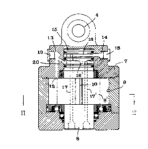
to the invention; and
Fig. 3 is a horizontal cross-sectional view on
line III-III in Fig. 2.
Detailed description of a preferred embodiment of the
invention
In Fig. 1, reference numeral 1 generally designates
a working implement in the form of a grapple harvester
hanging from the tip 2 of a crane by means of a rotator
designated 3 in its entirety. More particularly, the
rotator is hanging in a joint 4 permitting the implement
1 to swing relative to the crane tip. The rotator 3
also permits the implement to pi~ot in known manner
relative to the crane tip. A first pair of hydraulic
hoses 5 supply the rotator with hydraulic oil, while
a second pair of hoses 6 supply hydraulic oil to the
moving parts of the unit 1. These hoses are connected
to a pump and a hose, respectively, on a vehicle (not
shown) on which the crane is mounted.
Figs 2 and 3 illustrate in more detail the con-
struction of the rotator 3. The rotator comprises a
top or housing 7 within which a shaft 8 is rotatably
mounted by means of suitable bearings and gaskets. In
the area of a hollow space 9, the shaft 8 has a thickened
30 portion 8' in which two spring-loaded vanes 10, 10' are
mounted and divide the hollow space 9 into at least two
working or sub-chambers 11, 11'. Oil is supplied to,
and evacuated from, each of these working chambers 11,
11' via first ducts 12, 12' formed in the housing top.
In Fig. 2, reference numeral 13 designates one
of two bores to which two hydraulic hoses could be con-
nected in conventional manner via nipples. On conventional
~.

13~2l~3
rotators, these two hoses and bores serve to supply
the working chambers of the rotator with oil, more par-
ticularly via the ducts 12, 12'. Reference numeral 14
designates one of two similar bores which also could
be connected to a pair of hydraulic hoses for supplying
oil to the working implement via a swivel connection
which is designated 15 in its entirety and which com-
prises at least two annular hollow spaces 16, 16' commu-
nicating, at different levels, with two second ducts
17, 17' formed in the pivot shaft 8. However, in the
embodiment illustrated, not only the two bores 14 (only
one is shown in Fig. 2) but also the two bores 13 (only
one is shown in Fig. 2) are plugged by means of plugs
18, 19 or permanently closed in some other manner. In
addition, there is provided, according to the principle
of the invention, a branch duct 20 between the annular
hollow space 16' to the swivel connection 15 and the
bore 13 which in turn communicates with one of the rotator
working chambers via the duct 12. Similarly, a branch
duct (not shown) is provided between the second annular
hollow space 16 and the second (not shown) bore 13 which
in turn communicates with the duct 12' of the second
rotator working chamber.
By providing, in accordance with the invention,
branch ducts 20 between on the one hand the first ducts
12, 12' of the rotator working chambers and, on the
other hand, the second ducts 17, 17' within the pivot
shaft 8, viz. via the annular hollow spaces 16, 16'
of the swivel connection 15, the ducts 17, 17' in the
pivot shaft can be used for supplying oil to the rotator
working chambers, more particularly via the two hoses
5 extending from the pump and the tank on the vehicle
to the lower side of an attachment plate 21 by which
the implement 1 is mounted on the pivot shaft 8. In
this manner, there is no need for a hose connection
on the outside of the rotator top or housing, and all
supply of oil to the rotator working chambers occurs
via the ducts in the pivot shaft of the rotator.
~ ~ ~t~

Representative Drawing
A single figure which represents the drawing illustrating the invention.
Administrative Status

2024-08-01:As part of the Next Generation Patents (NGP) transition, the Canadian Patents Database (CPD) now contains a more detailed Event History, which replicates the Event Log of our new back-office solution.

Please note that "Inactive:" events refers to events no longer in use in our new back-office solution.

For a clearer understanding of the status of the application/patent presented on this page, the site Disclaimer , as well as the definitions for Patent , Event History , Maintenance Fee  and Payment History  should be consulted.

Event History

Description Date
Inactive: Agents merged 2013-10-21
Inactive: Expired (old Act Patent) latest possible expiry date 2009-06-09
Inactive: IPC from MCD 2006-03-11
Inactive: Late MF processed 1997-06-12
Grant by Issuance 1992-06-09

Abandonment History

There is no abandonment history.

Owners on Record

Note: Records showing the ownership history in alphabetical order.

Current Owners on Record
INDEXATOR AKTIEBOLAG
Past Owners on Record
ROLF HANSSON
Past Owners that do not appear in the "Owners on Record" listing will appear in other documentation within the application.
Documents

To view selected files, please enter reCAPTCHA code :


To view images, click a link in the Document Description column. To download the documents, select one or more checkboxes in the first column and then click the "Download Selected in PDF format (Zip Archive)" or the "Download Selected as Single PDF" button.

List of published and non-published patent-specific documents on the CPD .

If you have any difficulty accessing content, you can call the Client Service Centre at 1-866-997-1936 or send them an e-mail at CIPO Client Service Centre.


Document
Description 
Date
(yyyy-mm-dd) 
Number of pages   Size of Image (KB) 
Abstract 1993-10-31 1 23
Claims 1993-10-31 1 30
Cover Page 1993-10-31 1 11
Drawings 1993-10-31 2 49
Descriptions 1993-10-31 5 172
Representative drawing 2001-11-28 1 17
Late Payment Acknowledgement 1997-07-28 1 172
Fees 2003-05-28 1 40
Fees 1998-06-04 1 53
Fees 2001-06-05 1 51
Fees 2002-06-04 1 54
Fees 1997-06-12 1 45
Fees 1999-06-02 1 56
Fees 2000-06-08 1 54
Fees 2004-06-07 1 42
Fees 2005-06-07 1 42
Fees 2006-06-05 1 44
Fees 2007-06-07 1 51
Fees 2008-06-06 1 45
Maintenance fee payment 1996-06-03 1 53
Maintenance fee payment 1995-05-16 1 52
Maintenance fee payment 1994-05-19 1 60