Language selection

Search

Patent 1302944 Summary

Third-party information liability

Some of the information on this Web page has been provided by external sources. The Government of Canada is not responsible for the accuracy, reliability or currency of the information supplied by external sources. Users wishing to rely upon this information should consult directly with the source of the information. Content provided by external sources is not subject to official languages, privacy and accessibility requirements.

Claims and Abstract availability

Any discrepancies in the text and image of the Claims and Abstract are due to differing posting times. Text of the Claims and Abstract are posted:

  • At the time the application is open to public inspection;
  • At the time of issue of the patent (grant).
(12) Patent: (11) CA 1302944
(21) Application Number: 1302944
(54) English Title: EGG-TRANSPORTING APPARATUS
(54) French Title: DISPOSITIF POUR LE TRANSPORT DES OEUFS
Status: Term Expired - Post Grant
Bibliographic Data
(51) International Patent Classification (IPC):
  • B65G 49/05 (2006.01)
  • A01K 31/16 (2006.01)
  • B65G 17/16 (2006.01)
  • B65G 47/38 (2006.01)
(72) Inventors :
  • KUHLMANN, JOSEF (Germany)
(73) Owners :
  • JOSEF KUHLMANN
(71) Applicants :
(74) Agent: SMART & BIGGAR LP
(74) Associate agent:
(45) Issued: 1992-06-09
(22) Filed Date: 1986-07-11
Availability of licence: N/A
Dedicated to the Public: N/A
(25) Language of filing: English

Patent Cooperation Treaty (PCT): No

(30) Application Priority Data:
Application No. Country/Territory Date
P 35 25 460.2-22 (Germany) 1985-07-17

Abstracts

English Abstract


ABSTRACT
This invention relates to an apparatus for receiving,
transporting and releasing eggs more particularly in
poultry-breeding operations, the said apparatus comprising a
plurality of cages arranged one above the other in storeys and
egg-collecting belts in front of each storey of cages, an
egg-elevator being arranged in the vicinity of the outlet-end of
each egg-collecting belt, the said elevator comprising a circulating
conveyor-chain carrying small supporting frames which are adapted to
the size of the eggs and to which the eggs are transferred from the
egg-collecting belt, the said supporting frames being secured
pivotably to the said conveyor-chain.


Claims

Note: Claims are shown in the official language in which they were submitted.

The embodiments of the invention in which an exclusive
property or privilege is claimed are defined as follows.
1. An apparatus for receiving, transporting and releasing
eggs from a laying battery, in poultry-breeding operations, for
further processing, the said apparatus comprising a plurality of
cages arranged one above the other in storeys, with egg-collecting
belts in front of each storey of cages, and an egg-elevator arranged
in the vicinity of the outlet-end of each egg-collecting belt, the
said elevator comprising a circulating conveyor-chain carrying
supporting elements adapted to the size of the eggs, characterized
in that the supporting elements are in the form of small supporting
frames to which the eggs are transferred from the egg-collecting
belt, each supporting frame comprising a supporting lever secured
rigidly to one end thereof and extending upwardly at right angles to
the plane of the supporting frame, and the said lever being secured
pivotably to the said conveyor-chain by means of a pivot-pin.
2. An apparatus according to claim 1, characterized in
that the drive for the conveyor-chain of the egg-elevator is such
that the descending run of the conveyor-chain is in the vicinity of
the outlet-end of the egg-collecting belt.
3. An apparatus according to claim 1, characterized by a
system of deflecting sprockets in the vicinity of the outlet from
the egg-elevator and a stop in the vicinity of the said sprocket
system, extending into the path of supporting lever in such a manner
that when the said supporting lever bears upon the said stop, the
supporting frame carries out a tilting motion through about 90°.
- 6 -

4. An apparatus according to claim 2, characterized by a
system of deflecting sprockets in the vicinity of the outlet from
the egg-elevator and a stop in the vicinity of the said sprocket
system, extending into the path of supporting lever in such a manner
that when the said supporting lever bears upon the said stop, the
supporting frame carries out a tilting motion through about 90°.
5. An apparatus according to claim 1, 2 or 3,
characterized in that each supporting frame is made of a synthetic
material.
6. An apparatus according to claim 1, 2 or 3,
characterized in that the supporting frames consist of two
longitudinal frame parts and two transverse frame parts uniting the
said longitudinal frame parts, thus forming a rectangle the length
of which corresponds substantially to the width of the outlet end of
the egg-collecting belt.
7. An apparatus according to claim 4, characterized in
that each supporting frame is made of a synthetic material.
8. An apparatus according to claim 4, characterized in
that the supporting frames consist of two longitudinal frame parts
and two transverse frame parts uniting the said longitudinal frame
parts, thus forming a rectangle the length of which corresponds
substantially to the width of the outlet end of the egg-collecting
belt.
9. An apparatus according to at least claim 3,
characterized in that the stop is in the form of a slide-plate.
10. An apparatus according to at least claim 4,
characterized in that the stop is in the form of a slide plate.
- 7 -

11. An arrangement for removing eggs from laying houses
disposed at different levels, comprising a first conveyor at each
level, said first conveyors extending by the respective laying
houses so as to collect eggs from the same, and each of said first
conveyors having a discharge end; and a second conveyor for
transporting eggs away from the respective levels, said second
conveyor having an egg receiving section which extends by said
discharge ends, and said second conveyor including an endless driven
member defining an endless path, and a plurality of egg carriers
mounted on said driven member for movement along said path and each
including a frame-like element for cradling eggs, each of said
frame-like elements being substantially rectangular and including a
pair of spaced, essentially parallel longitudinal frame components
and a pair of spaced, essentially parallel transverse frame
components connecting the respective longitudinal frame components
to one another, and said second conveyor being designed so that said
frame-like elements are substantially horizontal in said receiving
section.
- 8 -

Description

Note: Descriptions are shown in the official language in which they were submitted.


1.3~?2~
This inventic)n relates to an apparatus for receiving,
transporting and releasing eggs, in a poultry-breeding operation,
from a laying battery, for further processing.
In poultry-breeding operations, the hen cages are arranged
one above the other in a multi-storey arrangement. Provided in the
vicinity of these storeys of cages is a so-called egg-collecting
belt which feeds the eggs released from individual cages to a
central collecting station.
According to the prior art, eggs are received from these
egg-collecting belts, arranged one above the other at each storey,
by forked gripper-elements and are fed to a central collecting
belt. Now these hook- or fork-shaped elements have the disadvantage
that they can easily damage the eggs, so that the proportion of
so-called cracked eggs occurring in these known apparatuses is
relatively large.
In generically similar German Utility Model 72 27 032,
buckets, scoops or cups are arranged on a circulating flat-link
chain, into which eggs arriving from the egg-collecting belt are
transferred by means of a lift table. Deflection of the said chain
causes the eggs to move in the buckets from one wall to the other,
after which they must still be transferred from the said buckets to
a deflecting or collecting plate. Thus, before reaching the final
collecting belt, whence they pass for further processing, the eggs
are deflected and handled several times. Here again, considerable
damage to the eggs is to be expected.
-- 2

~3~1ZS~
It is the purpose o~ the invention to provide an apparatus
for collecting eggs which will allow them to be transferred, without
any dif~iculty, from the egg-collecting belt to the said collecting
apparatus, whence they can be passed for further processing without
frequently moving back and forth.
According to one aspect of the present invention, an
apparatus for receiving, transporting and releasing eggs from a
laying battery, in poultry-breeding operations, for further
processing, the said apparatus comprising a plurality of cages
arranged one above the other in storeys, with egg-collecting belts
in front of each storey of cages, and an egg-elevator arranged in
the vicinity of the outlet-end of each egg-collecting belt, the said
elevator comprising a circulating conveyor-chain carrying supporting
elements adapted to the size of the eggs, characterized in that the
supporting elements are in the form of small supporting frames to
which the eggs are transferred from the egg-collecting belt, each
supporting frame comprising a supporting lever secured rigidly to
one end thereof and extending upwardly at right angles to the plane
of the supporting frame, and the said lever being secured pivotably
to the said conveyor-chain by means of a pivot-pin.
Preferably, the egg-elevator consists of small frames which
are individually pivotable and are carried upon a conveyor-chain.
These frames can accommodate one, or at the most two eggs, the said
eggs resting upon the frame-elements and being thus reliably held.
Located in the upper part of the said elevator is a system of
defleeting sprockets which is combined with a cam plate in sueh a
manner as to eause the frames to tilt, thus releasing the eggs.

13V;~9~
This deflecting sprocket system also reduces the conveying speed.
This allows the supporting frames to travel relatively slowly in the
release area, thus ensuring that the eggs are released gently and
without any problems.
Further advantageous configurations of the apparatus will
be apparent with reference to the following specification read in
conjunction with the drawings wherein:
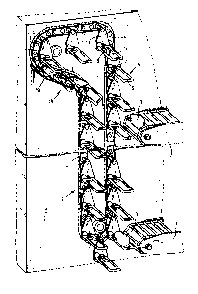
Figure 1 is a diagramatic side view of the upper end of an
egg-elevator, and
Figure 2 is a side view of the apparatus of the present
invention showing the manner in which eggs are received from two
egg-collecting conveyors.
In the drawings, 1 indicates an egg-collecting belt, a
plurality of such belts being arranged in storeys one above the
other. Located in front of the egg-collecting belt is an
egg-elevator 2, while 3 is an egg located upon the egg-elevator or
the collecting belt.
The egg-elevator itself consists essentially of a
circulating conveyor-chain 4 carrying small supporting frames 5
consisting of transverse elements 6 and 7 and longitudinal elements
8 and 9. Transverse frame element 7 is secured to a supporting
lever 10 which runs at right angles to the plane of the frame,
extends upwardly and carries at its upper end, a pivot pin 11 by
means of which supporting lever 10 and frame 5 are connected to
conveyor-chain 4. The said chain is driven in such a manner that
the run directed towards egg-collecting belt 1 descends while the
other run ascends.
-- 4

13~Z9'~
Located in the upper part of the egg-elevator is a systern
of deflecting sprockets 12, 14 and 15 which guides conveyor-chain 4
from descending run l~ outwardly beyond the vertical projection of
ascending run l7.
Provided in this area is a stop 18 in the form of a cam
plate l9 which causes the small frames to carey out a pivoting
motion, as shown clearly in Fig. l, making it possible for the egg
on the frame to be released.
Frames 5 are preferably made of a synthetic material which
is sufficiently stable but is also soft.
In this part oE the egg-elevator, the eggs are released
gently and are transferred gently from the egg-collecting belt to
the egg-elevator. The proportion of cracked eggs is therefore
considerably reduced overall.

Representative Drawing
A single figure which represents the drawing illustrating the invention.
Administrative Status

2024-08-01:As part of the Next Generation Patents (NGP) transition, the Canadian Patents Database (CPD) now contains a more detailed Event History, which replicates the Event Log of our new back-office solution.

Please note that "Inactive:" events refers to events no longer in use in our new back-office solution.

For a clearer understanding of the status of the application/patent presented on this page, the site Disclaimer , as well as the definitions for Patent , Event History , Maintenance Fee  and Payment History  should be consulted.

Event History

Description Date
Inactive: Expired (old Act Patent) latest possible expiry date 2009-06-09
Inactive: Reversal of will be deemed expired status 2007-07-26
Inactive: Office letter 2007-07-26
Letter Sent 2007-06-11
Inactive: Entity size changed 2002-04-30
Inactive: Entity size changed 1998-06-01
Grant by Issuance 1992-06-09

Abandonment History

There is no abandonment history.

Owners on Record

Note: Records showing the ownership history in alphabetical order.

Current Owners on Record
JOSEF KUHLMANN
Past Owners on Record
None
Past Owners that do not appear in the "Owners on Record" listing will appear in other documentation within the application.
Documents

To view selected files, please enter reCAPTCHA code :


To view images, click a link in the Document Description column. To download the documents, select one or more checkboxes in the first column and then click the "Download Selected in PDF format (Zip Archive)" or the "Download Selected as Single PDF" button.

List of published and non-published patent-specific documents on the CPD .

If you have any difficulty accessing content, you can call the Client Service Centre at 1-866-997-1936 or send them an e-mail at CIPO Client Service Centre.


Document
Description 
Date
(yyyy-mm-dd) 
Number of pages   Size of Image (KB) 
Abstract 1993-10-31 1 15
Cover Page 1993-10-31 1 12
Claims 1993-10-31 3 89
Drawings 1993-10-31 2 66
Descriptions 1993-10-31 4 111
Representative drawing 2001-11-28 1 21
Fees 2003-03-21 1 39
Correspondence 2000-05-08 1 27
Correspondence 2001-03-29 1 26
Correspondence 2007-07-26 1 14
Fees 1997-04-25 1 72
Fees 1996-05-06 1 56
Fees 1995-06-13 1 64
Fees 1996-07-04 3 88
Fees 1994-05-31 1 66