Note: Descriptions are shown in the official language in which they were submitted.
13V3~
-- 1 --
&~qrlcultural apparatus such as fertilizer spreader, sprayer or the like
This invention relates to an agricultural apparatus such as a fertilizer
sF)reader, sprayer or the llke bring to connected to and supported by a towing
vehlcle, the apparatus comprising a contsiner for storlng the material whlch is to
b~ spread and booms or the like extending sideways from the container and
supporting tubes which communicate with spreader rneans fastened to the booms.
Previously known apparatus of the above type comprise a central unit Wit~l
a container for the material to be spread or sprayed. From thi~ unit booms
provided wlth nozzle means extend perpendicular to the driving direction. The
apparatus can either be provided with a chassis and supporting wheels and be
towed by a vehlcle or have no chassis and wheels and instead be supported by thevehicle. ln both cases the track width is small compared to the total working
width and the movements that are created at the booms and In particular at its
outer ends are conslderable when the wheels of the apparatus or the towing
vehicle are passlng irregularities in the ground.
These movements mean great inconveniance. Great stress is created in the
booms snd at the 3Olning parts In the central unit which means risk for damages.The materlal whlch Is to be spresd 1~ al80 Irregularly distributed during these
movements.
Spring support and damping of the booms which i9 a method used on some
machlnes have prooved to be instlfficlent. On other machines the problem has
been solved by forming a rlgid llnit out of the two booms when they are extendedin working position. This unit is supported at a point which has the possibility to
move about a horlzontal axis which is parallell to the driving direction. Different
embodiments excist see for Instance 8ritish patent applicatlon No. 202807~.
If these systems are used on an apparatus which is supported by a towlng
vehicle the booms have to be placed behind the central unit which makes fllling
of the container troublesome. In order to facilitate filling as much as possiblethe booms should instead be placed at the sides of the container.
The purpose of this invention is to achieve an apparatus of the type
described above this apparatus being supported by the towing vehicle and being
so designed that rapid movements of the towing vellicle are not directly
converted into a corresponding movement of the boorns. At the same tirne the
.
.; - ~ .,, -
13~3~8
arrangement accordinq to the invention allows the booms to follow
a more permanent inclination of the towing vehicle for instance
when driving on a slope. This is achieved by a device which has
received the characteristics mentioned in the claims.
In a broad aspect, the invention provides an agricultural
apparatus for dispersing a certain substance such as fertilizer,
comprising:
- a container for storing said substance;
- booms extending sideways from said container and forming
in conjunction with said container a relatively rigid unit;
- a plurality of conduits mounted to said booms;
- spreader means in communication with said conduits, said
spreader means being mounted to said booms for delivering said
substance over a certain area;
- connecting means for attaching said agricultural apparatus
to a towing vehicle, said connecting means including:
a) a pair of arms in a spaced apart relationship
pivotally mounted to said rigid body about a generally horizontal
axis which is generally perpendicular to a direction of movement
of said agricultural apparatus;
b) resilient means between said arms and said rigid
unit for reducing the transmission of violent movements from the
towing vehicle to said agricultural apparatus; and
c) support shafts on said arms for engagement by the
towing vehicle to support said agricultural apparatus.
An embodiment of the invention will now be described with
reference to the accompanying drawings where fig. 1 in a plan
view shows a towing vehicle with an apparatus of the actual type,
fig. 2 and 3 show the apparatus from the side and from the rear
respectively whereas fig. 4 is a side elevation view of the
support device for the apparatus and fig. 5 is a side elevation
view of the same support device.
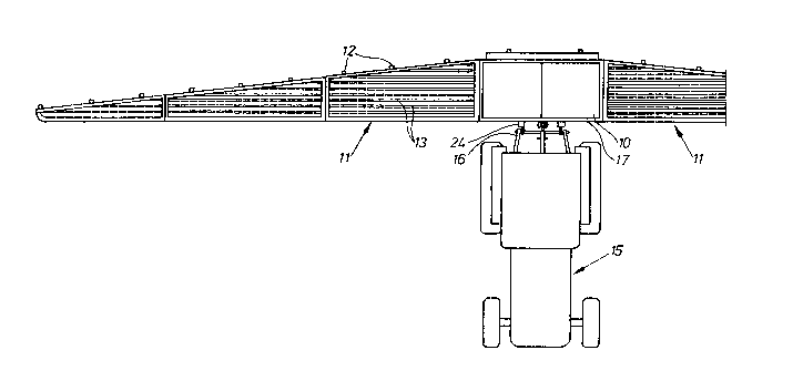
As appears from the figures the apparatus comprises a
container 10 in which the material to be spread is stored. This
container on each side supports extensions in the form of
.~,
'.. . ''' .. ''''
. .
13~D3~
-- 3 --
booms 11 extending horizontally outwards in its working
positions. The booms which are divided into sections are in a
conventional manner folded together during transport but in
extended position they together with the container 10 form a
rigid unit. The booms are provided with several nozzles 12 which
via tubes 13 communicate with a common feed device, not shown,
for transferring the material from the container into the tubes.
The apparatus also has a fan 14 which creates an air stream by
means of which the material is transported from the feed device
through the tubes to the nozzles. The apparatus is supported by
a towing vehicle 15 by a conventional three point support 16.
The container is on its vertical front wall 17 provided
with two pairs of brackets 18 on which two arms 19 are turnably
secured by means of shafts 20. These arms each have a support
shaft 21 to be joined to the fastening device of the towing
vehicle. The upper part of the arm 19 has a circular plate 22
with a central pin 23. The plate 22 abuts a rubber sleeve 29
which also abuts a plate 25 fixed to the container wall 17 and
having a central pin 26. The rubber sleeve 24 is thus clamped
between the container wall 17 and the arm 19. The support shaft
21 is placed between a central line A through the rubber sleeve
and a line B which is parallel to the line ~ through the shafts
20 of the arm. The support shaft 21 is moreover placed in front
of the turning shafts 20.
By this arrangement the distance between the boom tips and
the ground is mainly constant i.e the complete unit follows the
inclination of the ground since the towing vehicle follows this
inclination. In the event that the support shaft 21, in figure
5, moves upwardly as a result of a rapid upward movement of the
towing vehicle which occurs when driving over uneven terrain, it
causes the arm 19 to swing anticlockwise about the shaft 20
thereby compressing the rubber sleeve 24. Thus the upward
movement is not transferred directly to the container and the
booms. If the rear wheel on one side of the towing vehicle
should rapidly sink down into a hole in the ground the load on
the support shaft 21 on this side will decrease and be forced
:13~3~
- 3a -
forwards, downwards by the spring means. At the same side the
boom achieves a movement backwards, upwards with respect to the
towing vehicle. The movement of the boom on the other side
becomes the opposite. In practice this means that the apparatus
with the booms mainly keeps its position in the horizontal plane.