Note: Descriptions are shown in the official language in which they were submitted.
1303097
The present invention relates to a window-
raiser device for a motor vehicle.
A certain number of window-raiser devices for a
motor vehicle of the type comprising means for actuat-
ing a mechanism for raising and lowering the window,with arms in an X, in which the ends of the arms
comprise pads sliding in a slide of a support structure
comprising means for fastening the window are already
known in the state of the art.
These fastening means consist of, for example,
a stub of a lip of the fastening means, adapted in
order to engage in a recess of the window, as described
in European Patent Application EP-A-0,208,237.
Moreover, the document US-A-4,004,371 also dis-
closes means for fastening a window which comprise aplate in which two perforations are arranged and
through which two screws adapted in order to engage in
two corresponding holes of the window extend in order
to fasten this window on the plate and, therefore, on
2~ the rest of the raising and lowering mechanism of the
latter.
However, all these devices have a certain
number of drawbacks, particularly with respect to the
mounting thereof.
In fact, this mounting consists in introducing
the mechanism for raising and lowering the window
inside the door casing, in sliding the window through
the corresponding slot in the door and finally in
fastening the window in the fastening means of the sup-
port structure of the mechanism for raising and lower-
ing the window.
These operations have to be performed "blind"
inside the door casing to which access is very diffi-
cult. Moreover, because of the design of the raising
and lowering mechanism, which comprises pads sliding in
the slide of the support structure on which the means
for fastening the window are provided, this support
structure may move freely with respect to the rest of
the mechanism such that the fitters must grope for a
1303097
-- 2 --
reasonable length of time before finding the ideal
position for this support structure and therefore for
the fastening means w th respect to the complementary
fastening elements of the window, in order to achieve
S the fastening of the latter on the support structure.
Moreover, the guiding pads currently used
suffer from a considerable amount of wear which, with
time, gives rise to a play which upsets the operation
of the window-raiser device and introduces vibrations
which are the source of noises.
The invention therefore aims to solve these
problems by proposing a window-raiser device which is
simple, reliable, of a low cost price and which makes
it possible to ensure very easy mounting of the window
in the means for fastening the latter.
To this end, the subject of the invention is a
window-raiser device, particularly for a motor vehicle,
of the type comprising means for actuating a mechanism
for rais;ng and lowering the window, w;th arms in an X,
in which ends of the arms comprise pads sliding in
a slide of a support structure comprising means for
fastening the window, characterized in that breakable
stop means are provided in the path of movement of the
pads in the slide such that when the pads are up
against these stop means, they lock the support struc-
ture in position with respect to the pads and therefore
to the window-raiser mechanism and thereby determine a
position for mounting the window in the means for
fastening the window on the support structure, the stop
means being breakable by the pads at the time of the
first manoeuvre tending to separate them.
Advantageously, the pads have a rectangular
longitudinal section and they are mounted so as to
articulate about pivots fastened on the corresponding
ends of the arms.
The invention will be better understood with
reference to the following description, given solely by
; way of example and made with reference to the appended
1:~0309~
-- 3 --
drawings, wherein:
- Fig.l represents a partial view of a window-
raiser device according to the invention;
- Fig. 2 represents a detailed view represent-
ing a second embodiment of stop means included in thestructure of a device according to the invention;
- Fig. 3 represents another detail v;ew repre-
senting a second embodiment of fastening means
included in the structure of the device according to
the invention;
- Fig. 4 represents a side view illustrating
the link between an arm of a mechanism for raising and
lowering the window and a support structure included in
the structure of a device according to the invention.
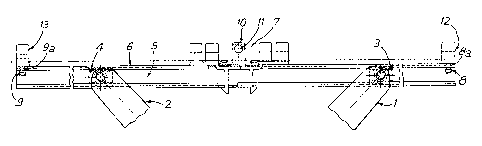
As may be seen in Fig.1, a window-raiser device
according to the invention comprises means (not shown)
for actuating a mechanism for raising and lowering the
window, with arms in an X, given reference numerals 1
and 2 respectively in this figure, in which the ends of
the arms 1 and 2 comprise pads 3 and 4, respectively,
sliding ;n a slide 5 of a support structure 6 compris-
ing means 7 for fastening the window (not shown~.
Since the means for actuating this mechanism for rais-
ing and lowering the window, with arms in an X, is well
known in the state of the art, they will not be described
in detail and it will simply be noted that these
actuating means may consist of manual means actuated,
for example, by a handle or electric means comprising
an actuating gear motor.
According to the invention, stop means 8 and 9
are provided in the path of movement of the pads 3 and
4, respectively, in the slide 5 of the support struc-
ture such that when the pads 3 and 4 are up against
the stop means 8 and 9 they lock the support structure
6 in position with respect to the pads 3 and 4 and
therefore to the rest of the window-raiser mechanism
and thereby determine a stable position for mounting
the window in the means 7 for fastening the latter on
1303097
-- 4 --
the support structure 6. In fact, by locking the posi-
tion of the support structure 6 with respect to the
pads by means of the stop means 8 and 9, the fastening
means 7 are also locked in a specific position, for
example in the path of movement of the complementary
means provided on the window in order to ensure the
fastening of the latter on the fastening means 7 of the
support structure. In this way, the fitter no longer
has to grope to find the ideal position for the fasten-
ing means 7. These fastening means consist, for exampleof a certain number of lips for centring and position-
ing the lo~er part of the window, one, 10, of these
lips comprising, for example, a stub 11 adapted in
order to engage in a corresponding recess of the window
in order to ensure the fastening of the latter on the
support structure.
The stops means 8 and 9 are breakable by the
pads 3 and 4 at the time of the first manoeuvre of the
means for actuating the mechanism for raising and lower-
ing the window which tends to separate the latter. Inthis way, once they are broken, these stop means 8 and
9 will no longer impede the normal operation of the
window-raiser device.
~ As may be seen on this Figure 1, the stop means
Z5 8 and 9 each consist of a protecting part extending
transversely in the slide 5 of the support structure,
these projecting parts being connected via zones 8a, 9a
of less resistance, to means 12, 13 for pos;tioning the
window on the support structure arranged at each end of
the latter.
However, and as may be seen on Fig. 2, the stop
means may also comprise fingers 14 extending longitudin-
ally in the slide 5 of the support structure 6,
these fingers 14 being connected via zones of less
resistance to means 15 for positioning the window on
the support structure 6.
Advantageously, the fing~rs 14 are retractable
inside recesses, for example 16, of the positioning
means, by means of the said pads at the time of the
. 1303097
-- 5
first manoeuvre of the actuating means tending to
separate them.
In this case also, the stop means are arranged
close to each end of the sl;de 5.
S As may be seen on Fig. 3, which represents a
variation in embodiment of the fastening means, the
latter may comprise, for example, two lips facing one
another, only one 17 of which is visible, fastened on the
support structure 6 and each comprising a recess 18
adapted in order to interact with a stub 19 which is
integral with the windows. Moreover, the guiding
means 20 consisting, for example, of inclined planes, may
also be provided on the lips in order to ensure guiding
of the stub 19 when it descends in the fastening means.
As is represented in Figs. 1 and 4, the pads
may have a rectangular longitudinal section and they
are mounted so as to articulate about pivots, for
example 21, like the pad 22 represented in Fig. 4,
these pivots being fastened on the corresponding ends
of the arms, for example 23.
Advantageously, each pad consists of two parts
22a, 22b fastened on one another, these pads being
arranged in a slide 24 of a support structure compris-
ing means for fastening the window and centring and
positioning 0eans, for example 25, of a type such as
described above.
In this manner, this structure of the pads
makes it possible to improve their movement in the
slide and prevents excessive wear thereof as was the
case in the state of the art. Moreover, the manoeuvr-
ing of the device for actuating the window is also en-
hanced.
Finally, each pivot, for example 22, may also
comprise breakable projecting parts, for example 26,
connected to the corresponding pivot via a zone 26a of
less resistance and locked between the two parts of the
pad in order to lock the latter in position with
respect to the pivot in order to facilitate its mount-
ing in the slide of the support structure, the
.~ .. s
1303097
projecting parts being breakable at the time of the
first manoeuvre tending to mo~e these pads.