Note: Descriptions are shown in the official language in which they were submitted.
~3~33~
TITLE OF THE INVFNTION
VACUUM CLEANER
BACKGROUND OF THE INVENTIO~
1. Field of the Invention
The present invention relates to a vacuum cleaner,
and more particularly to a vacuum cleaner having means
for killing noxious small organisms,such as mites,
trapped in the dust chamber of the cleaner kody.
2. Description of the Prior Art
The noxious small organisms, such as mites,
drawn into the dust chamber of the body of a vacuum
cleaner along with dust during cleaning are separated
off by a filter within the dust chamber without being
discharged from the cleaner but are likely to prolifera-.e
in the chamber, so that they must be killed completely.
It is known that mites and like noxious small organisms
are killed when exposed to hot air of about 50 C. Fig.
24 shows a kno~n vacuum cleaner which is so adapted.
Further Vnexamined Japanese Patent Publication SHO 62-
127026 discloses a cleaner of similar construction.
rrhe vacuum cleaner shown in Fig. 24 is so adapted that a
suction hose 51 inserted in the suction opening of its
body case 50 is connected at its forward end to a discharge
air outlet 53 of the bod~ case 50 for an electric fan 52
,
.
~3q~3~6
to circulate a hot discharge air stream from the fan 52
through a dust case 54 by way of the suction hose 51
and to thereby kill the mites and like noxious small
organisms within the case 54.
Thus, the body case 50 of the conventional
cleaner must be provided at its discharge side with the
discharge air outlet 53 which is small and serves also
as a socket for connection to the suction hose 51~
Further when mites and like noxious small organisms are
to be killed, the elongated suctlon hose 51 must be
manually set in position, while the hose 51 extending
outward from the body case 50 will bend or hang down,
rendering the case 50 unstable. The dust case 54 can not
be heated efficiently and requires a prolonged period
of time for heating since the discharge air circulates
through the elongated suction hose.
SUMMARY OF THE INVENTION
The present invention provides a vacuum cleaner
comprising a cleaner body having a dust chamber formed
with a suction opening and a fan chamber communicating with
the dust chamber and accommodating an electric fan therein,
the fan chamber having an air discharge opening, and
drive cont~ol means for controlling the operation of the
fan, the cleaner body being provided with an air channel
in its interior for holding a portion of the fan chamber
'.
~3~33~
at the air discharge side of the fan in communicati.on
with the dust chamber and closure means for closing the
suction opening of the dust chamber, the drive control
means comprising cleaning operation means for driving the
fan to thereby draw dust collecting air into the ~uction
opening, pass the air through the dust chamber and the
fan chamber and discharge the air from the discharge
opening for a cleaning operation, and organism killing
cperation means for drivlng the fan after the cleaning
operation to cause air to flow through the dust chamber,
the fan chamber and the air channel into the dust chamber
in circulation by the actlon of the closure means and
kill noxious small organisms in the dust trapped in
the dust chamber by heating.
Thus, the cleaner body of the present invention
is internally provided with an air channel for holding
the fan chamber in communication with the dust chamber
and also has~closure means for closing the suction opening
of the dust chamber. By virture of this construction,
::
the cleaner is adapted to perform~the usual cleaning
operation and also to operate f~or killing noxious
small organisms (such as~mites including Ornithonyosus,
: Demodex and Pediculoides, ticks,~ants,:etc.) in the dust
collected in the dust chamber by heating the organlsmsj
efficiently within a short period of time, with these two
,
~ 3- :
:
::
:: : :
- . .
:L3~3~ E;
modes only by controlling the operation of the electric
fan and by the action of the closure means.
The usual cleaning operation is performed by
the cleaning operation means whlch drives the fan to
draw dust collecting air into the suction opening, pass
the air through the dust chamber and the fan chamber and
discharge the air from the discharge opening. For
example, this means comprises a power supply circuit for
driving the fan, and a cleaning operation switch for
energizing and deenergizing this circuit.
On the other hand, the organism killing
operation is performed by the organism killing opera-
tion means, which drives the fan after the cleaning
lS operation to cause air to flow through the dust chamber,
the fan chamber and the air channel into the dust chamber
in circulation by the action of the closure means. For
example, this means comprises the above-mentioned power
suppl~ circui' for driving the fan, and an organism
~illing operation switch for energizing and deenergiz-
ing the circuit. Preferably, the circuit is deenergized
automatically in response to a -ise in the internal
temperature of the dust chamber or in accordance with
the duration of the operation instead of manipulating
the switch.
~33~6
From another viewpoint, the present invention
provides a vacuum cleaner which comprises a cleaner body
having a dust chamber formed with a suction opening and
a fan chamber communicating with the dust chamber and
accommodating an electric fan therein, the fan chamber
having an air discharge opening, a hot air supply unit
fittable to the suction opening for supplying hot air to
the dust chamber, and drive control means for controlling
the operation of the fan and the hot air supply unit,
the drive control means comprising cleaning operation
means for driving the fan to thereby draw dust coll.ecting
air into the suction opening, pass the air through the
dust chamber and the fan chamber and discharge the air
from the discharge opening for a cleaning operation, and
crganism killing operation means for driving the hot
air supply unit as fitted to the suction opening after
the cle~ning operation to supply hot air to the interior
of the dust chamber and kill noxious small organisms
in the dust trapped in the dust chamber by heating.
According to the invention, the noxious small
organisms in the dust trapped in the dust chamber can be
heated and thereby killed . efficiently and rapidly
merely by fitting the hot air supply unit to the suction
opening for supplying hot air to the interior of the
chamber.
:~L3~
The cleaner of the invention is operated for
cleaning in the usual manner by the same means as the
foregoing cle~ning operation meanc. On the other hand,
the organism killing operation is performed by the
organism kllling operation means for driving the hot
air supply unit as fitted to the suction opening after
the cleaning operation to supply hot air to the interior
of the dust chambe~ When the hot air supply unit
comprises a tubular member fittable to the suction opening
for guiding outside air into the dust chamber, and a
heater provided inside the tubular member, the organism
killing operation means comprises, for example, a
power supply circuit electrically connectable to the heater
when the tubular member is fitted to the suction opening
and also adapted to drive the fan, and a controlling
operation switch for energizing and deenergizing the
power supply circuit. As in the foregoing case, the
circuit is deenergized preferably automatically. The
hot air supply unit can be an assembly comprising a
mount member fittable to the suction opening, a heater
incorporated in the mount member and electrically
connectable to the power supply circuit for driving the
fan when the member is fitted to the opening, and a
small-sized electric fan similarly incorporated in the
mount member for supplying the heat of the heater to the
--6--
~3~33~;
dust chamber.
BRIEF DESCRIPTION OF THE DRAWINGS
Figs. 1 to 6 show a vacuum cleaner embodying
the invention;
Fig. 1 is a front view partly in section and
showing the embodiment;
Fig. 2 is a perspective view of the same;
Fig. 3 is a plan view partly in section and
showing the same;
Fig. 4 is a front view partly in section and
showing the same in cleaning operation;
Fig. 5 is a fragmentary perspective view showing
the same with a cover opened;
Fig. 6 is a diagram showing the electric circuit
diagram of the same;
Figs. 7 to 15 show another vacuum cleaner
embodying the invention;
Fig. 7 is a front view partly in secti~n and
showing the embodiment;
20Fig. 8 is a perspective view;
Fig. 9 is a plan view partly in section and
showing the embodiment;
Fig. 10 is an enlarged fragmentary view in
seciion of Fig. 7;
25Fig. 11 is a front view partly in section and
showing the embodiment during cleaning operation;
--7--
. .
13!'~33~?~
Fig. 12 is a fragmentary plan view shcwing the
same with a shutter plate opened;
Fig. 13 is a fragmentary perspective view of
a suction hose;
Fig. 1~ is a perspective view of the lower
portion of a plug member;
Fig. 15 is an electric circuit diagram;
Figs. 16 to 22 show another vacuum cleaner
embodying the invention;
Fig. 16 is a front view partly in section
and showing the embodiment;
Fig. 17 is a perspective view;
Figs. 18 (a) and (b) are respectively a front
view and a view in vertical central section both showing
a hot air supply unit;
Fig. 19 is an electric circuit diagrami
Fig. 20 is a rragmentary plan view showing the
construction of a suction opening portion;
Fig. 21 is a perspective view showing the
embodiment in cleaning operation;
Fig. 22 is a diagram showing the electric
circuit of the same during cleaning operation;
Fig. 23 is a view corresponding to Fig. 18 (b)
and showing another hot air supply unit embodying the
ir.vention; and
--8--
~L3~33~i
Fig. 24 is a sectional view schematically
showing a conventional vacuum cleaner.
DESCRIPTION OF T~E PREFERRED EMBODIMENTS
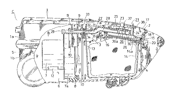
(1) The construction of a vacuum cleaner C embody-
ing the invention will be described with reference to
Figs. 1 to 6.
The cleaner C has a body case 1 comprising an
upper case member la and a lower case member lb. The case
1 has in its front portion a dust chamber 4 formed with
an upper opening 3 which is closed with a cover 2, and
in its rear portion a fan chamber 6 communicating with
the dus~ chamber 4 and formed with an ~ir discharge
opening 5.
An electric fan 7 accommodated in the fan
chamber 6 has a front fan case 7a which is held between
an upper support rib 9 on the upper case member la and
a lower support rib 10 on the lower case member lb, with
an annular cushion 8 provided between the case 7a and
the ribs. The fan case 7a thus fixedly provided separates
the chamber 6 in.o a suction side 11 and a.n air discharge
side.
A box-shaped filter 13 having air per~eability
and shape retentivity to serve as a dust collecting filter
is accommodated in .he dus, chamber 4 and is removable
through the upper opening 3. The filter 13 has removably
, . .... .
,-:
~3~33~i
accommodated therein a disposable paper bag filter 14
serving also as a dust collecting filter. The filter 14
comprises a paper bag having air permeability but not
permitting passage of noxious small organisms such as
mites therethrough. Indicated a~ 15 is a frame for
holding an opening plate 14a of the bag filter 14, and
at 16 a clamp for engaging the opening plate 14a. The
holding frame 15 rests on -che opening edge of the box-
shaped filter 13.
The cover 2 has a double-wall structure
comprising an outer cover member 17 and an inner cove~
member 18. The cover has a rear portion pivoted to the
upper case la and is biased in an opening direction at
all times by a spring 19 (see Fig. 4). The cover has its
front end engaged by a clamp member 20 proviced on 'che
lower case lb to hold the upper opening 3 closed.
The cover 2 is provided with a suction opening
portion 21 for connecting a suction hose 22 (see Fig. 4)
to the cleaner C. The opening portion 21 has a succion
opening 23 formed in the outer cover member 17 and
comprises a hose sockec 24 positioned under Ihe opening
23 and interposed between the outer and inner cover
members 17, 18, and a slidable shutter plate 25 serving
as closure means for openably closing the upper end of
the hose socket 24. A packing 26 provided under the
--10--
. . .; . .-
~3~33~
hose socket 24 is hermecically in pressing contac'c with
~che opening plate lD~a.
Indicated at 27 is an air channel provided
within the cleaner body, whereby a discharge air slream
from the fan 7 is circulated through the dust chamber 4.
The air channel 27 comprises a cover channel portion 28
and a body channel portion 29. The cover channel portion
28 is provided between the ou~er and inner cover members
17 and 18, and has one end communicating with an air
outlet 30 forme~ in a side portion of ~he hose soc)cet
24. The o~her end of the~channel portion 28 is projected
from the rear end 31 of the cover 2 opposed to a portion
33 of the body case 1 to provid~ an air inlet 32. The
air outlet 30 is closed when a connection tube 22a of
.he suction hose 22 is inserted in the sockel 24 as
seen in Fig. 4, whereas ,he outlet 30 is left open when
the .ube 22a is not inserced.
The body channel portion 29, which is provided
in the body case 1, extends from the discharge side 12
of the fan 7 forward through the upper support rib 9
and has an air outlet 34 in the body portion 33 opposed
to the air inlet 32. The air inlet 32 is provided with
a seal packing 35 which, when the cover 2 is closed,
seals off the junction beiween the inlet 32 and the
outlet 34, hermetically holding these portions in
.. . . . .
~31~333~6
communication with each other.
The cover channel portion 28 is provided with
a temperature sensor switch 36 and disposed in the vicinity
of the suction opening portion 21. The switch 36 has a
;-eset button 37 projecting outward from the outer cover
member 17 in the vicinity of the suction opening portion 21.
The switch 36 is turned on by depressing the reset button 37
and is t~rned off upon the sensor portion 36a thereof
detec~ing that the ~emperature of the discharge air
stream through the cover channel portlon 28 has reached
a predetermined temperature of 65 C which is hlgher
than 50 C at which mites or like no~lous small organisms
are killed. and the synthetic resin forming the cleaner body
remains free of thermal deforma.ion or like thermal
influence at the predetermined temperature.
The temperature sensor switch 36, although
provided in the cover channel portlon 28 in the present
embodiment, may alternatively be provided on the side
wall of the dust chamber 4, with the reset button
projecting from ~he lower case member 1D~
Indicated at 38 is ;3 limii swltch attached -to
the rear slde of the outer cover member 17 and opposed
to the eQge of ~he sucLion opening portion 21. When .he
shutter plate 25 closes the upper end of the hose socket
-12-
13~33(;~` E;
2~, ~he fron~ end of the shutter pla~ce 25 comes into
contacc wi,h the limit switch 38 to ac'~uate the switch 38
and energize to the fan 7 through the temperature
sensor swi'cch 36.
With reference to the electric circuit diagram
of Fig. 6, indicated at 39 is a control circuit, and at
40 a remote control unit mounted on a handle pipe of
the suction hose 22.
For a cleaning operation, the conneccion tube
22a of the suction hose 22 is inserted into the socket
24 with the shutter pla'ce 25 opened as seen in Fig. 4.
In this s-cate, the air outlet 30 of the cover channel
portion 28 is closed with the connection tube 22a, with
the result that the discharge air from the fan 7 is
discharg~d from the discharge opening 5 without circulat-
ing through ~he ~us~ chamber 4. Accordingly, mites and
like noxious small organisms are drawn in ~hrough the
suction hose 22 along with dust and collected in the paper
bag filter 14 within the dust chamber ~.
To operate the cleaner for ~illing -~he mites
and like small noxious organisms after the completion of
cleaning, ~che shutter plate 25 is close~ as seen in ~ig. 1,
whereby che limit switch 38 is actuated. Subsequently,
the reset button 37 is depressed, turning on the .empe~-
ature sensor switch 36 'o energize to the fan 7 for
-13-
~3~33~
rota~ion. with ,he suction opening portion 21 closed
with the shutter plate 25 at this time r a negative
pressure is produced n the dust chamber 4, causing the
dischaxge air from the fan 7 to flow inco the chamber 4
through the body channel portion 29 and the cover channel
portion 28. The air ihus flows repeatedly in circulation
and is heated with the heat released from the fan 7 to
heat the dus, chamber 4. The discharge air stream is
therefore heated to a ~;emperature higher than 50 C co
kill the mites and like noxious small organisms collected in
the bag filter 14. Upon the temperature reaching 65C, the
sensor switch 36 is turned off to si-op the fan and
complete the organism killing operaiion.
With the vacuum cleaner C described above,
the discharge air from the fan is circulated through
the dus-t chamber via an air flow channel provided in the
cleaner body, with che suction opening of the dust
chamber closed, so that the mites and like noxious
organisms trapped in the dust chamber can be easily
controlled using only the arrangement provided in the
cleaner body. Since the air channel permits the fan
chamber to communica es directly wi~h th~ dus. chamber~
the discharge air can be circulated over a shorter
disiance .han in the conventional cleaner which employs the
elonga-ted suction hose, efficiently heating the interior
-14-
., : .
~3~33~
of -'che dus-c chamber wi'chin a shorter period of time
to completely kill the noxious organisms. Furthex-
r,lorer 'she temperature sensor acts .o automatically stop
the fan so as not to overheat the discharge air,
consequently rendering the cleaner body free of thermal
deformation or like thermal influence -co assure safety.
(2) Another vacuum cleaner embodying the inven-tion
will be described below with referenee to Figs. 7 to 15.
The cleaner 100C has a body case 101 ~hich
basically has the same cons.ruction as the case of the
foregoing embodiment and therefore will not be described.
The cover 102 has a suc'cion opening portion 121
for connection to a suc'cion hose 122 (see Fig. 11). The
opening portion 121 has a suction opening 123 for~ed in
the outer eover member 117 and eorl~rises a hose socket
124 postioned under the opening 123 and interposed
between the upper and inner cover members 117, 118, and
a slidable sut'cer plate 125 for openably closing the upper
end of the hose socke'c 124. ~ith reference 'co Figs. 11
and 13 to 15, the hose soeket 124 is provided with a
pair of remote concrol socketsl28,128 which are electri-
cally connec'ced '50 remote control terminals 127, 127
when a connection tube 122a of the hose 1 2 is inserted
in~o the socket 124, and wi~h a recess 130 for a projec-
tion 129 on the tube 122a co fi-~ in for posi,ioning ~he
-
~3~P3;~
tube (see also Fig 12) The ~erminals 127 are connec~ed
to a remote control unit 126 on a ben~ pipe (not shown)
of the hose 122 for controlling the fan 107 A packing
131 is herme ically in pressing con-cact with the opening
plate 114a
,Indicated at 132 is an air channel provided
wi~hin the cleaner body, whereby a discharge air stream
from the fan 107 is circulated through ~he dust chamber 104
The air channel 132 comprises a cover channel portion 133
and a body channel portion 134 The cover channel portion
133 is provided between the outer and inner cover members
117~ li8, and has one end communica~ing with an air outlet
135 formed in a side portion of ,he hose socket 124 The
other end of the channel portion 133 is projected from
the rear end of the cover 102 opposed to a portion of
the body case 101 ~o provide an air inlet 136 The air
outlet 135 is closed when the connec-.ion tube 122a of
~he suction hose 122 is inserted in the socket 124 as
seen in ~ig 10, whexeas the outlet 13i is left open when
-the tube 122a is'not inserted
The body channel portion 134, which is provided
in the body case 101, ex_ends from the discharge slde 112
of the fan 107 forward through the upper support rib 109
and has an air outlet 137 in the body portion opposec to
-;-he air inlet 136 The air inlet 136 is p ovided with a
-16-
:~3~33~
seal packing 138 which, when the cover 102 is closed,
seals off the junciion between -~he inlet 136 and -.he
outle. 137, hermetically holding these por.ions in
communication with each other.
To kill noxious small organisms such as
mites, a plug member 139 serving as closure means is
removably fittable to the sucticn opening portion 121
as an attachment member in place of the connection tube
122a. The plug member 139 has a communication channel
142 provided with a lower bottom opening 141 and a side
opening 140 communicating with the air outlet 135, with
a packing 135a provided between the plug member and the
outlet portion. A temperature sensor switch 143 is
mounted on an upper kottom 142a of the plug member 139
and has a sensor portion 143a exposed to the communica-
tion channel 142 and a reset button 144. The reset
button 144 is biased by a spring 145 so as to project
upward through a hole 146 in the top of the plug member
139 and has a push pin 144a opposed to an actuating
button 143b of the switch 143. The sensor switch 143 is
turned on by depressing the reset button 144 and is turned
off upon the sensor portion 136a detecting that the
temperature of the discharge air through the communica-
'ion channel 142 has reached a predetermined temperature
of 65 C which is higher than 50 C at which mites or like
13~33(~6
noxious small organisms are killed. The synthetic resin
forming the cleaner body remains free of thermal deformation
or like thermal influenee at the predetermined temperature.
The peripheral ~all of the plug member 139 defining the
channel 142 is provided with a projection 147 for posi-
tioning the channel 142 in place when the plug member
is inserted into the socket 124 and with a pair of switch
terminals 148, 148 connected to the sensor switch 143.
The projection 147 is fitted in the recess 130 of the hose
soeket 124, and the switch terminals 148 are electrically
connected to the remote eontrol soekets 128.
For a cleaning operation, the shutter plate 125
is opened, and the eonneetion tube 122a of the suction
hose 122 is inserted into the socket 124 as illustrated
in Figs. 9 and 11. In this state, the air outlet 135 of
the cover ehannel portion 133 is elosed with the connec-
tion tube 122a, so that the discharge air from the fan 107
is discharged from the diseharge opening 105 without
circulating through the dust chamber 104. Accordingly,
mites and li]~e noxious organisms are drawn in through the
suction hose 122 along with dust and eollected in the
paper bag filter 11~ within the dust chamber 104.
To operate the cleaner for killing the mites
and like noxious small organisms after cleaning, the eonnec-
tion tube 122a is removed from the hose socket 124, and the
-13-
~3~33~6
channel portion 142 of the plug member 139 is inserted
into the socket 124 as seen in Figs. 7 and 10.
Subsequently, the reset button 144 is depressed, turning
cn the temperature sensor switch 143 to supply power
to the fan 107 for rotation, whereupon a negative pressure
is created in the dust chamber 104, causing the discharge
air from the fan 107 to flow into the chamber 104 through
the body channel portion 134 and the cover channel
portion 133. The air thus flo~Ts repeatedly in circulation
and is heated with the heat released from the fan 107 to
heat the dust chamber 104. The discharge air stream is
therefore heated to a temperature higher than 50 C to
kill the mites and like organisms collected in the bag
filter 114. Upon the temperature of the air stream
reaching 65 C, 'he temperature sensor switch 143 is
turned off to stop the fan 107.
With the vacuum cleaner lOOC described above,
the discharge air from the fan is circulated through the
dust chamber via an air channel provided in the cleaner
body, and a plug member as an attachment member, is
removably fittable to the suction openinq poriion of the
dust chamber to cause the air channel to communicate
with the dust chamber via a communication channel in the
plug member. Accordingly, the mites and like noxious
small organisms trapped in the dust chamber can be easily
-19-
~3~3~
killed merely by attaching the plug member to the
cleaner body. Since the dust chamber is adapted to
communicate with the fan chamber through the air channel
and the communication channel within the cleaner body,
the discharge air can be circulated over a shorter
distance than in the prior art in which the elongated
suction hose is used, consequently heating the interior
of the dust chamber efficiently and rapidly to completely
kill the noxious organisms. Furthermore, the temper-
ature sensor switch automatically stops the fan so asnot to overheat the discharge air, thereby rendering the
cleaner body free of thermal influence such as thermal
deformation to assure safety.
Although a temperature sensor switch is used
in the foregoing embodiments (1) and (2) for automatically
stopping the electric fan in the organism killing
operation, a timer switch is alternatively usable for
automatically bringing the fan out of operation upon
lapse of a specified time interval, e.g. 2 to 6 minutes.
(3) Another vacuum cleaner embodying the invention
will be described with reference to Figs. 16 to 22.
~ eferring to Figs. 16 and 17, the vacuum
cleaner 200C has a canister-type cleaner body 201 comprising
an upper case member 202 and a lower case member 203.
The body has in its front portion a dust chamber 206
-20-
3L3~33~;
formed with an upper opening 105 which is closed with a
cover 204, and in its rear portion an electric fan 207
the suction slde of which is in communication with the
dust cha~ber 206.
A box-shaped filter 208 having air permeability
and shape retentivity to serve as a dust collecting filter
is accommodated in the dust chamber 206 and is removable
through the upper opening 205. The filter 208 has removably
accommodated therein a disposable paper bag filter 209
serving also as a dust collecting filter which comprises a
paper bag having air permeability but not permitting passage
of noxious small organisms such as mites therethrogh.
Indicated at 210 is a frame for holding an opening plate 209a
of the bag filter 209. The holding frame 210 rests on the
opening edge of the box-shaped filter 208.
The cover 204 has a double-wall structure
comprising an outer cover member 211 and an inner cover
member 212. The cover has a rear pcrtion pivo~ed to the
upper case member 202 and a front portior. engaged by a
clamp member 213 provided on the lower case member 203 to
hold the upper opening 205 closed.
The cover 204 is provided with a suction opening
portion 214 for connecting a suction hose 215 (see ~ig.
21) to the cleaner 200C. The opening portion 214 has a
suction opening 216 formed in the oute- cover member 211
and comprises a hose socket 217 positioned under the
-21-
~3~33~6
opening 216 and interposed between the outer and inner
cover membe~s 211, 212, and a slidable shutter plate 218
for openably closing the upper end of the hose socket ~17.
T~7ith reference particularly to Figs. 21 to 22, the suction
hose 15 has connected thereto by an extension tube 221
electric suction means 220 for use on floors which means
includes a rotary brush rotatable by an electric motor
219. A bent pipe 222 at the forward end of the suction
hose 215 has accommodated therein a remote control unit
223 which has a variable resistor 223a and a brush switch
223b serving as a clear.ing operation switch, whereby the
fan 207 is on-off controlled and has its number of revolutions
controlled, and the ele^tric motor 219 is on-off
controlled. The hose socke~ 217 has a pair of remote
control termlnals 224, 224 for electrical connection to
the remote control unit 223, and a pair of terminals
225, 225 for supplying power to the motor 219 in the
suction means 220 from a commercial 100-V power source.
Indicated at 226 is a hot air supply unit
removably fittable to the suction opening portion 214
as an attachment member. ~7ith reference to Figs. 18 (a)
and (b), the unit 226 comprises a heating tube 230
serving as a tubular member and housing a heate 227,
such as thermistor having positive temperature character-
istics, attached to a mount plate 228, the tube 230 having
~13~133~
air intake apertures 229 in its front side. The unit
226 further comprises a spigot 232 extending downward
from the heating tube 230, having a hot air outlet 231 at
its lower end and fittable in the hose socket 217. A
temperature sensor switch 233 attached to the top wall of
the heating tube 230 is covered with a shelter plate 235
formed with an air port 234. The sensor switch 233 has
a reset button 233a projecting outward from the uni' 226
through a top hole 236 of theheatlng tube 230. The switch
233 is turned on when the reset button 233a is depressed
and is heated through the shelter plate 235 with hot air
flowing through the heating tube 230. The sensor switch
233 is turned off when the sensor portion 233b thereof
detects that the temperature of the hot air has reached
a predetermined level, e.g. 70 C, which is beyond
50 C, l.e. the temperature at which mites and like
noxious organisms are killed, and which will not thermally
deform or otherwise thermally influence the synthetic
resin forming the cleaner body. Since the shelter plate
235 prevents the flow of hot air from coming into direct
contact with the sensor switch 233, the time taken for
the switch 233 to reach the predetermined temperature
is lengthened b~ a specified time interval (e.g. about
1 to 2 minutes), whereby the switch 233 is adapted to
operate like a timer. The hot air supply unit 226
-23-
133~
further has a pair of secondary terminals 237, 237
electrically connectable to the p~ir of remoLe control
terminals 224, 22~, and a pair of heater terminals 233,
238 electricall~ connectable to the pair of power supply
terminals 225, 225. These secondary terminals 237 and
the heater terminals 238 are left exposed outside the
unit 26.
With reference to Fig. 19 showing the electric
circuit of the cleaner when the unit 226 is fitted to
the socket 217, the unit 226 includes a heater circuit
240 for connecting a parallel circuit of the heater 227
and a relay ,239 tothe heater terminals 238, 238 via the
tempera~ure sensor switch 233, and a control circuit 242
for connecting a series circuit of a normally closed
contact 239a of the relay 239 and a resistor 241 to the
secondary terminal 237, 237. The cleaner body 201
includes a revolution control circuit 243 serving as a
power supply circuit for the fan 207 and connected to
the remote control Lerminals 224, 224. The resistor 241
is controlled along with the heater 227 by the switch
233 to control the revolution contrcl circuit 243, thereby
reducing the number of revolutions of the fan 207 and dimmish-
ing the suction force, whereby the velocity of hot air
to be supplied to the dust chamber 206 from the unit 226
is decreased. Thus, the resistor 241 serves as means for reducing
-24-
: ' . , ~ ,
,
~3~13~
number of revolutions. The resistor 241 and
the relay 239 are arranged on the side face of the
temperature sensor switch 233.
When the cleaner is to be operated for cleaning,
the connection tube of the suction hose 215 is inserted
into the hose socket 217, and the remote control unit
223 is manipulated to on-off control the fan 207, control
the number of revolutions thereof and on-off control the motor
219 cf the suction means 220. The mites and like noxious
small organisms drawn in through the hose 215 along with
dust are collected in the bag filter 209 in the dust
chambe~ 206.
To operate the cleaner for controlling the
organisms after cleaning, the spigot 232 of the hot air
15 supply unit 226 is fitted into the hose socket 217 in
place of the connection tube of the suction hose 215,
and the reset button 233a is depressed, whereby -~he
temperature sensor switch 233 is turned on to supply
commercial l~0-V power to the heater 227 and the relay
20 239 through the power supply terminals 225, 225. The
heater 227 is immediately heated. With the relay 239
thus energized, the resistor 241 is connected to the
revolution control circuit 243 through the remote control
terminals 224, 224, which in turn rotates the fan 207 at a
reduoed number of revolutions to give a decre~ed suction force to
-25
~L3~33~;
draw hot air having a temperature of about 70 C
through the heater 227 into the dus~ chamber 206 via the
suction opening portion 217 at a low rate. Consequently,
the interior of the dust chamber 206 is heated to above
50 C to kill the mites and like noxious small organisms
trapped in the bag filter 209. Upon lapse of a specified
period of time, the switch 233 reaches the predetermined
temperature (70 C), whereupon the switch 233 is turned
off to turn off the heater 227 and stop the fan 207,
whereby the controlling operation is completed.
Fig. 23 shows another hot air supply unit
embodying the invention and different from the correspond-
ing unit of the above embodiment. Indicated at 244 in
the drawing is a shelter plate covering the top wall of
the unit 226 and having one end bearing on a mount plate
228, and at 245 an air port opposed to the mount plate
228. This embodiment is so adapted that hot air easily
flows into contact with a temperature sensor switch 233
through the air port 245 in the shelter plate 244 when
the flow rate of hot air greatly decreases, for example,
owing to the clogging of the paper bag filter 209, whereby
the switch 233 is immediately turned off to precl-lde the
thermal deformation of the cleaner body 201 or the hot
air supply unit 226.
With the vacuum cleaner 20QC described above,
-26-
.
.
:' ' ' ' ~ :
3;~
a hot air supply unit as an attachment member is
provided with a heater and a temperature sensor switch,
so that merely by attaching the unit -to the cleaner body,
power ca.n be supplied to the heater through supply
terminals to cause hot air to flow into the dust chamber,
whereby the mites and like noxious small organisms trapped in
the chamber can be readily killed Further since the
hot air flows into the dust chamber directly from the
unit, the orgnisms can be killed completely more
rapidly and more efficiently than in the prior art wherein
the long suction hose is used. The 'emperature sensor
switch automatically turns off the heater, rendering the
cleaner body or the hot air supply unit free of thermal
deformation or like thermal influence to assure safety.
Although a temperature sensor switch is used
in the above embodiment (3) for automatically turn ng
off the fan and the heater in the organism killing
operation, a timer switch is alternatively usable for
automatically stopping the operation of the fan and the
heater upon lapse of a spe~ified time interval, e.g. 2
to 6 minutes.
-27-