Note: Descriptions are shown in the official language in which they were submitted.
~3~3S~;~
This invention relates to an integrated hydraulic
quick change coupler for attaching and detaching a tool
for use on wheel and track loaders and materials handlers
having an hydraulicall~ operated loader arm and includes a
feature permitting both locking the tool to the loader and
tilting the tool by means of the same hydraulic mechanism.
Background of the Invention
In materials handling and earth moving machinery
it i5 highly desirab'e to provide means for quickly inter-
changing different tools, such as buckets, blades,hammers, forks, ji~ booms, grapples, brooms, etc.,
(collectively hereinafter referred to as ''tool~s)~ If
such tools can be remotely latched and unlatched from the
tractor cab without need for additional manpower so much
the better.
There are various arrangements in the art for
accomplishing this purpose but often they involve complex
or unreliable mechanisms. None so far as I am aware pro-
vides for both locking the tool in place and thereafter
tilting it sideways by the same hydraulic mechanism. In
; fact, all seem to require separate sets of cylinders to
accompish these two results.
Accordingly, it is an object of the present
invention to provide an improved and simplified quick
change loader coupler with optional means for both locking
the tool to the tractor and tilting the same by means of
the same hydraulic mechanism.
Summary of the Invention
In accordance with the invention there is pro-
vided a coupler for attaching and detaching a tool for useon wheel or track loaders and material handlers having an
hydraulically operated arm, comprising a coupler frame
hingedly mounted at the end of the arm adapted to be swung
in a vertical plane by means on the arm, coacting raising
and locking means on the frame and tool, coacting locating
and pivotal means on the frame and tool beneath the rais-
~3~3~
-- 2 --
ing and locking means, the coactiny raising and lockingmeans being adapted to engage each other as said frame and
tool are moved into coupling engagement thereby raising
the tool and locking the upper portion of the tool to the
coupler frame, the coacting locating and pivotal means
being adapted to become mutually engaged as coupling is
completed and to remain engaged until decoupling, bearings
mounted on the rear face of the tool for engagement with
: portions of the frame when coupled, locking means on the
frame and tool beneath the locating and pivotal means for
~ positively locking the lower portion of the tool to the
:~ frame after coupling, and means for engaging and disengag-
: ing the locking means to permit attachment to and detach-
ment of the tool from the frame.
In preferred embodiments, the locating and piv-
otal means cornprises a tapered central pivot pin mounted
on one of the frame and tool and a cooperating socket on
the other thereof for receiving the pin; the coacting
: raising and locking means comprises a radius plate mounted
on the frame in a plane generalIy parallel to that of the
frame and forwardly thereof and a receptacle mounted on
the top rear face of the tool to be coupled and adapted to
receive and retain the upper edge portion of the radius
plate as the coupler is moved into coupling engagement
with the tool, thereby raising the tool and locking the
upper portion of the tool to the coupler frame after
coupling, the pivot pin being located at the focus of
curvature of the radius plate, and the locking means
beneath the locating and pivotal means comprises a pair of
tool connection pivot pins extçnding rearwardly from the
lower rear face of the tool to be connected and locking
means on the frame adapted to engage the pivot pins to
retain the lower portion of tne tool in coupled engagement
with the frame.
In a more preferred embodiment, means are pro-
vided on the ends of the last named pivot pins for pre-
~3~35~
-- 3
venting relative axial movement of the pins and locking
means engaged therewith while the tool is coupled to the
frame, the tapered surface of the central pivot pin is
adapted to lift the tool as coupling is completed so as to
disengage the curved surface of the radius plate from the
bearings when the tool is coupled, hydraulic actuating
mechanism is mounted on the frame and coacting means are
provided on the frame and the rear face of the tool for
actuation by the hydraulic mechanism for (a) locking the
lower portion of the tool to the frame when coupled (b)
unlocking the same for uncoupling and (c) for tilting the
tool about the axis of the pivot pin while coupled.
Still further ob~ects, features and advantages of the
invention will become apparent from the following detailed
description of preferred embod~ments thereof taken in con-
~unction with the accompanying drawings.
Brief Descrlption of the Drawings
Fig. 1 is a view in perspective showing the parts
of one form of the novel coupler of the invention, not
embodying the tilting feature, as mounted on the end of a
loader bucket arm and on the rear face of a tool (in this
case a fork) to be coupled thereto;
Fig. 2 is a view in perspective showing a modi-
fied coupler of the invention as applied to a bucket
coupled to the end of a loader arm again not embodying the
side tilting feature and employing manual rather than an
hydraulically operated locking mechanism;
Fig. 3 is a view in perspective showing the parts
of the novel coupler mechanism embodying the tilting fea-
ture as mounted on the end a loader bucket arm and on therear face of the tool (bucket) separated from each other
but preparatory to coupling;
Fig. 4 is a side view of the embodiment shown in
Fig. 3 showing how the respective parts of the coupler
- 35 engage each other as coupling is initiated;
~3~35-~
-- 4
Fig. 5 is a similar view of the same a-fter
coupling is completed;
Fig. 6 is a view in perspective of the embodiment
of Figs. 4 and 5 ln the condition as seen in Fig. 5;
Fig. 7 is a view similar to Fig. 3 showing the
coupler system of the invention as applied to attaching a
fork instead of a bucket;
Fig. 8 is a view similar to Fig. 6 of another
embodiment of the invention with side tilting feature
employing hydraulically actuated rocker arms in place of
direct actuation from cylinder rods;
Fig. 9 is a view similar to Fig. 8 illustrating a
still different embodiment with side tilting employing two
double acting cylinders and roller-cam arrangement to
accomplish tllting; and
Fig. 10 is a schematic of one hydraulic control
and actuating mechanism suitable for use with the
invention, although other known hydraulic mechanisms may
be employed.
Detailed Description of Preferred Embodiments
Embodiments with Side Tilting
Embodiments equipped with side tilting are illus-
trated in Figs. 3 - 9.
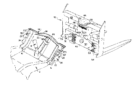
Refarring first to Figs. 3 - 7, a presently pre-
ferred embodiment of the invention as applied to a loader
bucket will be described. To the loader bucket arm 12 of
a wheel or track loader (not shown) is attached a coupler
frame 14, pivoted on pins 16 for swinging in a vertical
plane actuated by loader bucket cylinder 18 and loader
bucket link 20 in a manner well-known in the art. In the
case of a materials handler an analagous mounting of the
frame would be made. On the sides of frame 14 are mounted
lock cylinders 22 and 24 having pistons and piston rods
30, 32, respectively. The rods carry at their ends
bevelled downwardly facing locking trunions 26, 28 for up
and down reciprocation when the rods are actuated by their
:
~3~3~jf~
respective cylinders 22, 24. The trunions when disengaged
are prevented from accidental rotation by tracks or guides
25, 27. Forwardly of each trunion 26, 2~ is a coupler end
bearing 3~, 36, respectively.
Also on the front of the frame 14 and projecting
upwardly from its top is a radius plate 38 having an
arcuate upper rim 40 for a purpose below described.
The front side of frame 14 also carries a tapered
coupler central pivot pin 70 located beneath the plate 38
and pro~ecting forwardly of the frame.
Complementing the elements mounted on the frame
14 are cooperating members on tool 42, in this case a
bucket to be attached to the frame 14 by means of the
novel coupler. At the top of the rear face of the tool is
15 securely mounted a radius pl.ate receptacle 44 defined by a
steel plate affixed to the top of the tool by welding or
the like. It has a downwardly pro;ecting skirt 46 defin-
ing with the rear surface 43 of bucket 42 the pocket or
receptacle 44 having bearaing 44A ( Fig. 4) for receiving
20 and retaining the top edge of plate 38 during and after
the coupling procedure. Extending rearwardly from the
lower portion of surface 43 are two mu-tually spaced tool
connection pivot pins 52, 54 provided with adjustable
shoulders 56, 58. Also mounted on the rear face of the
25 tool are three tool face bearings 60, 62, 64 to be engaged
by elements of frame 14 when the latter is fully coupled.
In order to accomplish the side tilting function,
the tool 42 also is provided with a central pivot pin bore
72 which faces pin 70. Pin 70 is tapered, as best seen in
Fig. 4, for the purpose hereinafter described. It is
clear that these parts could be reversed, the pin being
mounted on the tool and the bore provided in the frame.
In Fig. 7 a fork tool has been substituted for
the bucket of Figs. 3 - 6. See description of Fig. 1
35 ( infra).
~3~3S~
-- 6
The operation of the embodiments of Fig. 3 - 9 is
as follows, referring first to Fig. 4, assuming that the
tool is resting on the ground in front of the loader, the
latter is advanced with the frame 14 swung forwardly and
downwardly a sufficient distance so that the rim 40 of
plate 38 is below the bottom edge of skirt 46 of recepta-
cle plate 44. Now the loader is moved ahead until the rim
40 is beneath skirt 46. Actuation of cylinder 18 now
swings frame 14 upwardly and backwardly with plate 38
caught in the receptacle formed behind skirt 46 and with
its rim bearing on the bottom surfaces of the pair of tool
mounting bearings 66, 68 which project rearwardly from
face 43 of tool 42 beneath skirt 46. Further pivoting of
the ~rame lifts the tool and allows its face to swing
against the ~ace of frame 14. In this position (Fig. 5)
the forward face o~ the frame 14 and the rearward face of
tool 42 are approximately parallel and the rear of rim 40
bears against inside of lip 46 and end bearings 34, 36
engage bearings 60, 64. As coupling is completed tapered
pin 70 enters socket 72 thereby lifting the tool 42 with
respect to the frame 14 and thereby disengaging the rim 40
of radius plate 38 from the bearings 66,68 while the tool
is in use.
To lock the tool on to the frame cylinders 22 and 24
are successively actuated (Figs. 5 and 6) extending
trunions 26, 28 downwardly to engage pins 52, 54 between
their respective shoulders 56, 58 and the face of the tool
42. To release the tool, the procedure is reversed.
First, the trunions are retracted. With the tool resting
on the ground, the loader is backed away as the frame 14
is swung forwardly, thus releasing the cooperating locking
elements from each other. The operation of the Fig. 7
embodiment is the same as for Figs. 3 - 6.
Side Tilt Actuation
Turning now to the side tilt actuation feature,
when the trunions 26, 28 are locked behind shoulders 56,
~l3~?3S~
-- 7
58 on pins 52, 54, it is apparent that tool 42 cannot be
detached from the frame 14, being held at the bottom by
the shoulders and at the top by engagement of plate 38
behind the lip 46 of member 44. At the same time,
however, it can be seen that if one cylinder rod is
extended and the other simultaneously retracted, the tool
42 will pivot on pin 70 one way or the other. Hydraulic
control means are provided to accomplish this function as
will now be described.
Referring to Fig. 10, the loader or materials
handler is provided with an hydraulic system actuated by
oil furnished under suitable pressure by pump 74. Oil is
delivered from pump 74 through line 76 to valve 78 which
is single spool valve, four-way spring centered, operated
manually or electrically as desired, the spool stem being
indicated b~ the numeral 79. Oil may be delivered selec-
tively through lines 82 or ~4A to valve 80, a motion con-
trol valve provided with cross-over cylinder reliefs. All
valves used in carrying out the invention are conventional
and standard in the industry.
Comrnunicating with valve 80 through line 84 and
inlet port 86 is a four-way solenoid operated valve spool
87, spring biased at full extension for normal tool opera-
tion and adapted when the solenoid is energized to shift
the valve spool to the opposite extreme. Valve 87 is pro-
vided with two work ports in addition to port 86. work
port 88 opens into line go which, in turn, communicates
with the lower chambers of both cylinders 22 and 2~
through ports 94 and 96. When solenoid 92 is actuated for
tool removal, port 86 is placed in communication with line
go through port 88. Oil discharging from cylinder 22
travels through line 102 to port 100 to tank 98. When the
solenoid valve is not actuated, work port 86 communicates
with work port 100 through line 102 to the driving chamber
of cylinder 22. The driving chamber of cylinder 24 is
connected directly to motion control valve 80 through line
,~
~ i"
~3~3S~;4
-- 8
104. Work ports 106 and 108 of spool valve 78 may be
alternately shifted by operation of the valve spool to
discharge oil into tank 110, as will be explained below.
Mode of Operation of Hydraulic S~stem
Coupling is initiated with both cylinders 22, 24
fully retracted. After the tool 42 has been picked up and
swung against the frame 14 so that the bevelled locking
trunions 26, 28 are in alignment with the shouldered pivot
pins 52, 54, the hydraulic controls are actuated to extend
the piston rods of cylinders 22, 24, one after the other,
into locking engagement with the pivot pins. Oil may be
first introduced through lines 82, 84 and 102 to engage
trunion 26 with its pin 52, and then introduced through
lines 84A an~ 104 to engag~ trunion 28 wi-th pin 54. Once
locked to their respective pins, the rods of both cylln-
ders remain so engaged untll it is desired to detach the
tool from the frame.
To accomplish detachment of the tool, by appro-
priate adjustment of the several valves, oil is fed
through lines 82, 84, port 88 and line 90 to the lower
chambers of the cylinders. This causes the cylinder pis-
tons to simultaneously retract, the oil in the upper end
of cylinder 22 being discharged into tank 98 and the oil
from the top of cylinder 24 being discharged through lines
104 and 84A into tank llO, which may be the same tank as
tank 98.
In accordance with the side tilting function, to
tilt tool 42 clockwise, as seen in Fig. 10, oil is fed to
the upper chamber of cylinder 24 by appropriate adjustment
of the control valves. This causes rod 32 to extend.
This action forces a corresponding amount of oil from
beneath the piston 25 to discharge through port 96 and
through line 90A into the lower chamber of cylinder 22
through port 94. The geometry of the cylinders is chosen
so as to be equal throughout tool rotation. Equal cylin-
der displacement allows the oil to be transferred from one
.~
` ~3~?3S~
cylinder to the other during tilting in either direction
or during overload or when in a tool llfloat" grading mode,
while at the same time the rods remain tightly e~gaged
with the tool connection pivot pins.
For side tilting in the opposite direction, the
oil is fed through lines 82, 84 and 102 to the upper part
of cylinder 22, thus extending rod 30 and rocking tool 42
counterclockwise. Again, oil forced from the lGwer cham-
ber of cylinder 22 i5 transferred into the lower chamber
of cylinder 24 through line 90A.
Alternative Tilting Mechanisms
Referring to Fig. 8, in this form of the inven-
tion a pair of vertical cylinders 22A and 2~A is mounted
on the frame 1~. Rods 30A, 32A are directed upwardly,
instead of downwardly as ln the previous embodiment.
Rocker arms 112, 114 are pivoted on pins 116, 118. The
inboard ends of arms 112, 114 are pivoted to rods 30A, 32A
by pins 120, 122 and the outboard ends are pivoted to arms
124, 126 by pivot pins 128, 130.
In this form of the invention arms 124, 126 have
replaced the direct connection of the cylinder rods to the
bevelled rod trunions. The latter are reciprocated by
actuation of the cylinders in an analagous manner into and
out of locking engagement with the tool connection pivot
pins on the tool as before. Manifestly, when one cylinder
rod is extended its rocker arm depresses that side of the
tool, tilting it accordingly.
Attaching and detaching of the tool to the frame
are accomplished as in the previous embodiment.
Fig~ 9 illustrates a still further modified form
of locking and tilting mechanism according to the
invention. A pair of cylinders 22B and 24B, shown mounted
horizontally end to end, replaces vertically arranged cyl-
inders of the previously described embodiments. At the
~ 35 ends of the rods of these cylinders are mounted rollers
; 132, 134 adapted to roll in tracks 136, 138, respectively.
~L3~3~
-- 10 --
It is clear that vertical mounting of these cylinders is
possible with suitable alternative track arrangement, if
desired.
The coupler serves to couple the tool 42 to the
frame 14 as in the previous embodiments, the pin 70 seat-
ing in the bore formed in the tool 42, as before, and
serving as a pivot for side tilting. In this embodiment
the cylinder rods are retracted during coupling and
decoupling. Once the tool has been swung flush against
the surface of the frame 14, the rollers 132, 134 are
extended into engagement with their respective inclined
tracks 136, 138.
The mode of operation then becomes similar to
that of the previous embodiments. When the rod of cylin-
der 24B is e~tended roller 134 rolls up track 138, tiltingthe tool cloc]cwise. The hydraulic system is analagous to
that of the previous embodiment, the oil displaced from
the outer chamber of cylinder 24B being transferred to the
outer chamber of cylinder 22B, thus permitting its rod to
retract an equal distance and roller 132 to roll
downwardly in track 136 a corresponding distance.
The tool 42 in this embodiment remains locked to
the frame during operations by reason of the side walls
140, 142 which retain the rollers in the tracks.
Couplers without Side Tiltin~
Figs. 1 and 2 illustrate two embodiments of the
coupler of the invention without the side tilting feature.
Turning first to Fig. 1, the loader bucket arm 12
of a wheel or track loader (not shown) is shown. To the
end of the arm is attached a coupler frame 14, pivoted on
pins 16 for swinging in a vertical plane actuated by
loader bucket cylinder 18 and loader bucket link 20 in a
manner well-known in the art. On the sides of frame 14
are mounted lock cylinders 22C and 24C having bevelled
downwardly facing trunions 26, 28 fastened to the piston
rods 30C, 32C for up and down reciprocation when actuated
~3~35i~
by their respective cylinders. Forwardly of each trunion
26, 28 is a coupler end bearing, 34, 36, respectively.
The cylinders and rod of this embodiment are abbreviated
in length as compared to those of the previously described
embodiments since they are not called upon to perform a
side til-ting function but only a locking function.
Also on the front side of the frame ]4 and pro-
jecting upwardly from its top is a radius plate 38 having
an arcuate upper rim 40 for the same purpose as in the
previously described embodiments.
Complementing the elements mounted on the frame
14 are cooperating members on -tool 42, in this case a fork
to be attached by means of the novel coupler. At the top
of the rear face of the tool is securely mounted a radius
plate receptacle 44 formed by a steel plate afflxed to the
top of the tool by welding or the like. It has a
downwardly pro~ectlng sklrt ~6 deflnlng with the rear sur~
face of upper cross member 48 a pocket or receptacle for
receiving and holding the top edge of plate 38 during and
after the coupling procedure. Extending rearwardly from
the face 43 of lower cross member 50 are two mutually
spaced tool connection pivot plns 52, 54 provided wlth
adjustable shoulders 56, 58. Also mounted on the rear
face of the tool are three tool face bearings 60A, 62A,
64A to be engaged by elements of frame 14 when the latter
ls fully coupled but not for the purpose of pe~mittlng
relative rotary motion.
The coupllng and decoupling operation of this
embodiment is the same as the previous embodiments and
wlll not be again described. When the tool has been swung
against the frame the face of the frame 14 and the rear-
ward face of tool 42 are parallel and the front of plate
40 bears against bearing 62A and end bearings 34, ~6
engage bearings 60A, 64A.
To lock the tool onto the frame, cylinders 22C
and 24C are actuated in succession, extending downwardly
~3~
- 12 -
trunions ~6, 28 which engage pins 52, 54 forwardly of
their respective shoulders 56, 58. Referring to Figs. 4
and 5, it will be seen that the locking is essentially the
same as for the side tilting versions of the novel
coupler. To release the tool, the procedure is reversed.
`~ First, the cylinders retract the trunions 26, 28. With
the tool resting on the ground, the loader is backed up
and the frame 14 swung forwardly, thus releasing the coop-
erating locking elements from each other.
10In this embodiment, once locked to the arm 12,
the tool 42 can be raised and lowered and pivoted on pins
16, but cannot be tilted sideways.
Alternate Non-Tilting Embodiment
This embodiment is shown in Fig. 2 wherein like
numerals refer to like parts. In this case manual locking
devices replace the cylinder actuated locks of the previ-
ously described embodiment.
As shown in Fig. 2, the tool is a bucket 42A in
place of a fork, as in Fig. 1. When the plate 38 advances
into the receptacle 44 behind skirt 46 and lifts the tool
42A by hearings 66,68 so that it can be swung against the
face of the frame 14A the levers 26A, 28A are in raised
position (not shown~ so that the tool connection pivot
pins can advance beneath them. When the rear face of the
tool is flush with the front face of the frame the two
levers are manually swung to locking position with the
-shoulders 56, 58 engaging the levers and preventing dis-
placement of the tool.
The disconnect procedure is the same as in the
Fig. 1 embodiment except that the levers 26A, 28A are man-
ually raised to release the tool connection pivot pins.
Summary of Features
The invention provides the first tractor loader
offering an integrated hydraulic quick change side tilting
means; the coupling mechanism is light weight and close-
coupled when engaged. Buckets, blades, hammers, forks,
~3~3~
- 13 -
jib booms, grapples, brooms, etc., can be remotely latched
and unlatched from tractor cab. The side tilt mechanism
is built in as an integrated part of the coupler without
the incorporation of additional hydraulic cylinders or
structures. A single pair of hydraulic cylinders not only
locks the tools on, but also tilts them approximately 12
degrees to either side (24 degrees total rotation) which
permits establishment of new grades by tilting the bucket,
i.e., road building, ditching, landscaping, etc. This is
not possible with current state of the art rigid mounted
quick couplers.
When fully tilted to either side, angle dozing
can be accomplished by rolling the bucket leading edge to
a vertical position. In the tilted position, compacted
materlals are easily penetrated by the corners of the
bucket and it is also easier to get under rocks, concrete
slabs or asphalt slabs.
When transporting pipe! building materials, etc.,
on side hills, especially when utilizing forks, the
objects can be leveled to prevent spillage. Also, objects
can be placed on surfaces which are laterally nonparallel
to the tractor loader. When equipped with forks, the fork
tips can be tilted to get under unparallel objects, i.e.,
pallets, pipes, logs, etc.
The hydraulic flow control valve compensates for
pin joint wear and keeps the hydraulic cylinder trunnions
tightly engaged. Cylinder crossover relief valve protec-
tion prevents structural damage by allowing excessively
high pressure oil to exhaust from one cylinder to the
opposite cylinder while keeping both cylinders tightly
engaged. The hydraulic circuit allows the coupler tilt
cylinders to simultaneously retract for tool disengagement
or to extend for tool engagement; the inadvertent disen-
gagement of one cylinder will not release a tool. Both
cylinder rod trunnions must be retracted to clear the tool
connection pivot pin shoulders.
3S~
While there has herein been disclosed and
described a presently preferred embodiment of the
invention, it will nevertheless be understood that the
same is by way of illustration and not by way of
limitation, and it is intended that the scope of the
invention be limited only by the proper interpretation to
be afforded the appended claims.
.